
Summary of Contents for Electronaut M97
- Page 1 ELECTRONAUT COMPANY M97 COMPRESSOR/LIMITER USER’s GUIDE Serial Number Built By Build Date Ship Date Line Voltage set to Revision 0, January 2016...
- Page 2 ELECTRONAUT COMPANY M97 COMPRESSOR/LIMITER USER’S GUIDE 2 SERIOUSLY. Read this entire manual before plugging in and turning on the M97! Refer servicing to qualified personnel only! To prevent electric shock, do not operate the M97 near water or moisture!
-
Page 3: Table Of Contents
BALANCE CALIBRATION INSPECTION PROCEDURE OPENING THE CRATE BALANCE/CHASSIS REMOVING THE M97 FROM THE CRATE THOROUGH INSPECTION AT THIS POINT THE M97 PROCEDURE SHOULD BE PROPERLY CALIBRATED AND READY FOR SERVICE CONFIGURATION FRONT PANEL REAR PANEL REFERENCE B+ ADJUST (325V) KNOB... - Page 4 ELECTRONAUT COMPANY M97 COMPRESSOR/LIMITER USER’S GUIDE 4 SUGGESTED SET-UP FOR SIDECHAIN/INTERLOCK ACKNOWLEDGEMENTS TRANSIENT LIMITING: EXTERNAL REIN NARMA UNDERSTANDING THE EFFECTS LINKING TWO M97S FOR STEREO DR. DANIEL FLICKINGER OF THE AC AND DC THRESHOLD BLOCK DIAGRAM OF SIGNAL AND MIKE AND KAY DORROUGH...
-
Page 5: Contact Information
Chicago, IL 60612 All information provided in this manual is thought to be accurate and free of errors at Product: the time of printing; however, Electronaut M97 Compressor/Limiter Company shall not be held liable for any errors Declaration: or omissions in this manual, nor any... -
Page 6: Thank You Sincerely
flaws and all, just as there are musicians who have labored tirelessly to for adding the M97 Compressor/Limiter to Something interesting started to happen perfect every riff in the Beatles’ discography. your system. This compressor is the result of... - Page 7 flaws; what made it status quo is better for every musician who But does the M97 sound like a Fairchild or not? great was that it expanded the usability of the ever wants to make a record. We can let...
-
Page 8: Getting Started
See Figure 3. applying power to the M97. 1) Inspection 2) Configuration Lift the M97 and foam caps from the crate and 3) Installation OPENING THE CRATE set it on a sturdy table surface. Remove the 4) Calibration foam endcaps and plastic wrapping. -
Page 9: Thorough Inspection Procedure
THOROUGH INSPECTION If the inspection process causes any doubt Set the FUNCTION switch to NORMAL, as as to the condition of the M97 upon arrival, shown in Figure 5. PROCEDURE please contact Electronaut immediately to It’s a good idea to thoroughly inspect the M97,... -
Page 10: B+ Adjust (325V) Knob
The LINE VOLTAGE switch is old-school and to find the center, turn the knob in one power from the M97. See ““POWER SCHEME” specifies the voltages as 115 or 230; however, direction continuously until it stops, then on page 29. -
Page 11: Installation
M97 is powered on. NOTE: These instructions assume that you will have access to the rear panel of the M97 after it NOTE: has been installed into your rack. If your The fan has a service life of 80,000 hours,... -
Page 12: Calibrating The Balance
DC currents at idle with no audio present, The regulating action is generally sufficient the M97 measures the audio balance using a to stay calibrated within 1-2%, so adjustments precision sine wave test tone. should be fairly rare. -
Page 13: Figure 13 - The Ac Threshold Control Should Be Set To The Maximum Counter-Clockwise Position During The Balance Procedure
Figure 17 — The front panel BALANCE knob is used to to the ATTENUATOR position, then adjust the adjust the symmetry of the audio amplifier input attenuator until a level of 0 dB is displayed. in order to minimize distortion. ELECTRONAUT COMPANY M97 COMPRESSOR/LIMITER USER’S GUIDE 13... -
Page 14: Balance/Chassis
ELECTRONAUT COMPANY M97 COMPRESSOR/LIMITER USER’S GUIDE 14 Bear in mind that as the M97 approaches a be achieved after experimenting with other perfect balance, the 2nd harmonic is reduced settings. NOTE: until it is eventually buried in the noise floor. -
Page 15: Reference
“off” mute REFERENCE function at the most counterclockwise position. To get the most out of the M97, it is Once the AC and DC Thresholds and the recommended that the remainder of this Attack and Release controls have been set up, manual be thoroughly read and understood. -
Page 16: Figure 20 - The High Frequency Response Can Be Extended By Setting The
ELECTRONAUT COMPANY M97 COMPRESSOR/LIMITER USER’S GUIDE 16 when = 100 ohms SOURCE Figure 20 — The high frequency response can be extended by setting the INPUT ATTENUATOR to zero and driving the input with a lower impedance source signal, as shown here when driven by a 100 ohm signal. -
Page 17: The Input Attenuator And The High Frequency Response
Ultimately, the input level. point became moot; the M97 can be set to What’s “Miller” capacitance? provide either a Fairchild-like roll-off or a more Vacuum tubes exhibit a tiny amount of modern extended frequency response. -
Page 18: The Controlling Amplifier
ELECTRONAUT COMPANY M97 COMPRESSOR/LIMITER USER’S GUIDE 18 THE CONTROLLING AMPLIFIER AC THRESHOLD The AC and DC Threshold are explained in more detail in the section titled The AC Threshold is the input attenuator to ““UNDERSTANDING the effects of DC THRESHOLD the controlling amplifier, which receives its... -
Page 19: Release
Distortion will be obvious if the ATTACK time • engage the high-pass switch is set to its fastest setting (fully counter- clockwise) and the M97 is set for heavy There are no cut-and-dry rules to these limiting. settings; they will need to be determined through experimentation. -
Page 20: Understanding The Effects Of The Ac And Dc Threshold Controls
ELECTRONAUT COMPANY M97 COMPRESSOR/LIMITER USER’S GUIDE 20 UNDERSTANDING THE EFFECTS OF THE AC AND DC THRESHOLD CONTROLS Average Peak Not all variable-mu compressors provide(d) the means to adjust the DC threshold. The Fairchild 660 and 670 did provide such a control,... -
Page 21: Compression Curves
• When the DC Threshold is at the minimum settings at a fixed DC Threshold setting. The position, the curves have a soft knee, Some of the compression curves that the M97 graph on the left shows the AC Threshold resulting in a fairly low compression ratio. -
Page 22: A Note About Workflow
ELECTRONAUT COMPANY M97 COMPRESSOR/LIMITER USER’S GUIDE 22 is useful when the DC Threshold is at maximum, since all the possible output levels in the compression region are above +4 dBu. A NOTE ABOUT WORKFLOW Once the AC and DC Threshold controls have been set, the amount of compression can be controlled by the INPUT ATTENUATOR. -
Page 23: The Metering System
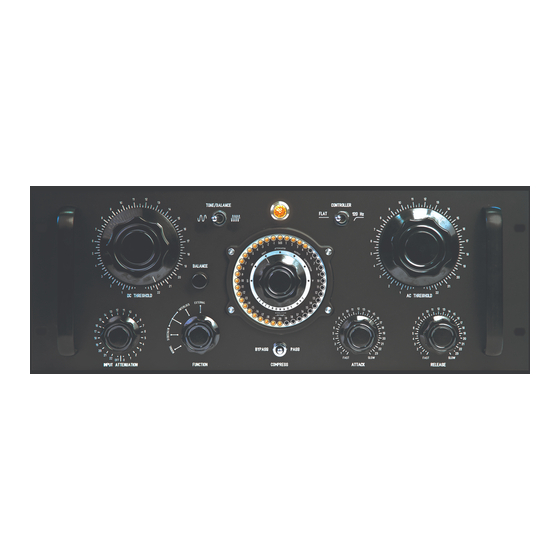
INPUT ATTENUATOR are visible on the Figure 27 — The center of the M97’s interface is the program material is being affected by the 40 dB peak and persistence meter with the METER MODE meter in ATTENUATOR mode. -
Page 24: The Signal Generator
MAKING GOOD USE OF THE The meter displays the audio appearing at TONE AND METER The M97 has a built-in signal generator that the OUTPUT. produces a low-distortion sine wave test tone Below are a couple of tips on using the tone When TONE or BALANCE mode is at +4 dBu. -
Page 25: High Pass Filter
A signal appearing at the INPUT XLR is routed through the audio amplifier, which operates as a fixed-gain line amplifier with a gain of approximately 17 dB. In PASS Mode, the controlling amplifier is disconnected and has no effect. ELECTRONAUT COMPANY M97 COMPRESSOR/LIMITER USER’S GUIDE 25... -
Page 26: The Function Switch
The unit operates as a stand-alone limiter. buss connector will provide the bias to the Other limiters which are connected to the M97 For stereo compression using two M97 AUDIO amplifier, and therefore set its gain. Compressor/Limiters, both units should be set through either the INTERLOCK or EXTERNAL to INTERLOCK mode, and a 1/4”... -
Page 27: Linking Two M97S For Stereo
It is also possible to use different settings on each unit to alter the influence that each channel has over the stereo limiting action. ELECTRONAUT COMPANY M97 COMPRESSOR/LIMITER USER’S GUIDE 27... -
Page 28: Block Diagram Of Signal And Control Circuitry
INPUT OUTPUT RECTIFIER ATTACK & RELEASE TRANSFORMER GAIN REDUCTION METER SAMPLE POINT SIDECHAIN INPUT XLR CONTROLLING DC THRESHOLD AC THRESHOLD INPUT PAD/HIGH PASS AMPLIFIER TRANSFORMER Figure 32 — A simplified block diagram of the M97’s signal path and controlling circuitry. -
Page 29: Power Scheme
A rocker switch at the rear panel IEC power inlet disconnects the line voltage from the unit. Use this switch to completely disconnect the power from the M97 if you plan to leave the M97 powered off for an extended period of time. -
Page 30: Replacing The Fuses
USER’S GUIDE 30 REPLACING THE FUSES INTERNAL FUSES To access the internal fuses, it is necessary to de-install the M97 from The M97 consumes a maximum of 240 watts continuously under the equipment rack and remove the top cover. normal use, and is protected by two separate sets of fuses:... -
Page 31: Replacement Fuse Part Numbers
SERVICE V10b 5749W Matched octet. Table 2 —Part numbers for the two pairs of fuses in the M97 are shown. optional substitute: 6386 Matched quartet. The location of the internal fuses is at the center of the rear edge of in place of V13a and V13b the main printed circuit board, as shown in Figure 36. -
Page 32: Figure 36 - The Main Printed Circuit Board, Showing The Location Of The Internal Fuses And The Tube Positions
ELECTRONAUT COMPANY M97 COMPRESSOR/LIMITER USER’S GUIDE 32 INTERNAL FUSES V10a V10b V13a V14b V14a V13b Figure 36 — The main printed circuit board, showing the location of the internal fuses and the tube positions. -
Page 33: Optional Remote-Cutoff Tubes
Please contact Electronaut prior to experimentation to ensure compatibility and to reduce the potential hazards. The circuit topology of the M97’s audio amplifier is similar to the Fairchild 660/670 in that eight triode sections are required; four in parallel per side in a push-pull configuration. -
Page 34: Tube Socket Wiring And Tube Compatibility
Electronaut first before attempting anything unusual. REPLACING THE TUBES With the exception of the remote-cutoff tubes, all the tubes used in the M97 are standard, should be readily available at guitar amplifier repair NOVAL B9A shops and online tube resellers, or through Electronaut directly. -
Page 35: Warranty & Registration
In the unlikely event of a defect, the original purchaser shall contact Electronaut to arrange a return of the M97 to the factory where it will be repaired without charge for parts and labour. The M97 will then be returned to the customer via prepaid freight and insurance through a carrier of Electronaut’s choice. -
Page 36: Specifications
ELECTRONAUT COMPANY M97 COMPRESSOR/LIMITER USER’S GUIDE 36 SPECIFICATIONS Maximum Gain: Approximately 17 dB Frequency Response (with Input Attenuator set to -6 dB): 20 Hz to 20 kHz + / – 1.3 dB Frequency Response ): 15 Hz to 53 kHz + / – 1.3 dB... -
Page 37: Acknowledgements
Dorrough Electronics for allowing me to redesign their meter and implement it in new DR. DANIEL FLICKINGER and interesting ways in the M97 Compressor/ Limiter. Despite his relatively short career in professional audio, Dr. Flickinger’s contribution to audio technology was prolific, innovative, EARLY BELIEVERS and influential. -
Page 38: Table Of Figures
Figure 19 — The INPUT ATTENUATOR is a 3-pole 23-position balanced bridged-T Figure 3 — The M97 is insulated from shock and suspended in place by two stepped attenuator..........15 foam end-caps. - Page 39 ......35 Figure 39 — Tube bases that are compatible with the M97......36...
Need help?
Do you have a question about the M97 and is the answer not in the manual?
Questions and answers