Sign In
Upload
Manuals
Brands
Electroline Manuals
Control Unit
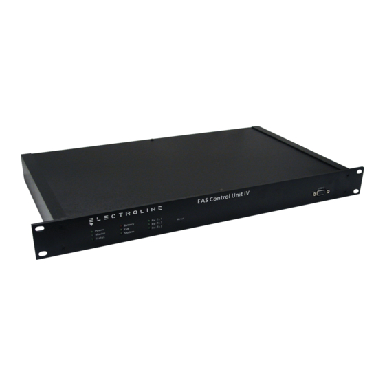
Control Unit IV
Electroline Control Unit IV Manuals
Manuals and User Guides for Electroline Control Unit IV. We have
1
Electroline Control Unit IV manual available for free PDF download: Reference Manual
Electroline Control Unit IV Reference Manual (146 pages)
Brand:
Electroline
| Category:
Control Unit
| Size: 1 MB
Table of Contents
Table of Contents
3
About this Manual
8
Conventions
9
1 Product Description
11
General Introduction
13
Carrier Options
13
Table 1-1: Identification of Carrier Type
13
Compatibility with Previous Versions
14
Certifications
14
Roles
14
Subscriber Tier Management
14
Figure 1-1: the Control Unit's Role in a Cable TV Network
15
Return Path Monitoring
16
Figure 1-2: the Control Unit's Role in Return Path Monitoring
16
Features
17
Billing System and Host Computer Interfaces
17
Tiering Systems
17
Subscriber Capacity
18
Table 1-2: Nominal and Actual Capacity
18
Redundancy System
19
Diagnostics
19
Upgradability
19
Physical Characteristics
20
Enclosure
20
Internal Features
21
Table 1-3: Control Unit Ports
21
Reference
23
2 Installation
25
Handling
27
Precautions
27
Mounting the Unit
28
Hardware Requirements
28
Mounting the Unit in a Rack
28
Figure 2-1: Installation of the Unit in an Equipment Rack
28
Setting up the Host Computer
29
Using Hyperterminal to Set up a Link with the Control Unit
29
Using the Workabout to Set up the Control Unit
32
Figure 2-2: Connecting the Workabout to the Control Unit's COM 3 Port for Setup
32
Setting up a Modem
33
Cable Assemblies and Applications
34
Figure 2-3: Connection Cables for a Single Control Unit
34
Figure 2-4: Redundancy Kit Cables
34
Connecting the Control Unit
35
Figure 2-5: Control Unit Connection
35
Connecting the Control Unit to the Host Computer or Modem
36
Connecting the Control Unit to the CATV Network
37
Connecting the Control Unit's Power Cord
37
Connecting the Control Unit's Test Ports
37
Connecting a Master Unit to a Backup Unit
38
Figure 2-6: Connections in a Redundancy System
39
Connecting the Control Unit for Setup
40
Figure 2-7: Connecting the Control Unit's COM 3 Port to a Computer for Setup
40
3 Setup
41
COM Port Characteristics
43
COM Port Protocols
44
Terminal Protocol
44
Packet-Switched Protocols
44
Table 3-1: Control Unit Protocols Used with Various Billing System Providers
44
Access Levels
45
Limited Access
46
Full Access
46
Logging off a Session
47
Viewing the Unit's Setup
48
Starting a Setup Session
49
Table 3-2: Mandatory Parameters on COM 3
49
Setup Procedure
50
Logging on with a Password
50
Setting the Time
50
Setting the Date
51
Changing the Password
52
Accessing the Setup Screen
52
Setting up the COM Ports
53
Table 3-3: COM 2 Synchronization Settings for the Redundancy System
53
Table 3-4: Data Configurations Possible on COM Ports 1 and 2
55
Table 3-5: System Types Supported by each Protocol
58
Table 3-6: Protocol Variations
59
RF Watchdog Setting for a Single Control Unit
60
Setting the Control Unit's ID Code
61
Setting the Carrier Tag
62
Saving the Setup
62
Redundancy Systems
63
Setting up the Control Units in a Redundancy System
63
Activating the Redundancy Failure Notification
64
Checking the Redundancy Diagnostic at Startup
65
Synchronizing the Master and Backup Units
66
RF Watchdog Settings for Redundancy Systems
67
4 Subscriber Statuses
69
Opening a Session on the Control Unit
71
Setting Subscriber Statuses
71
Displaying Subscriber Statuses
72
Setting the Tier Status of a Group
73
Table 4-1: Scan Time as a Function of Nominal Capacity
73
Displaying a Group's Tier Status
74
Sending an Immediate Group Command
76
Setting the Sequencer to a Specific Group
76
Finding Subscribers by Tier Status
77
Finding a Subscriber's Tap Number
78
5 Maintenance
81
Hardware Maintenance
83
Replacing the Fuse
83
Figure 5-1: Fuse Holder Removal
83
Figure 5-2: Spare Fuse Holder
83
Replacing the Battery
84
Figure 5-3: Internal View of the Control Unit IV with a RAM Expansion Board
85
Expansion Slots
86
Adding Expansion Boards
86
Removing or Replacing the RAM Expansion Board
86
Figure 5-4: RAM Expansion Board Installation
87
Transferring Subscriber Status Data
88
Downloading Subscriber Statuses
88
Uploading Subscriber Statuses
89
Upgrading the Control Unit's Firmware
92
Installing the Upgrade Program
92
Running the Upgrade Program
93
System Verifications
96
Monitoring the Status Leds
96
Checking the Programming Information
96
Checking the RAM
96
Resetting the Control Unit
97
Changing the Modulator or Demodulator Frequency
98
Requirements
98
Connecting the Workabout
98
Figure 5-5: Connection for Programming
98
6 Troubleshooting
101
Table 6-1: Verification of Status Leds
103
Checking the Power and Battery
104
Checking the FSK Signal
104
Table 6-2: Procedures for Troubleshooting Problems with the RF out Port
106
Table 6-3: Procedures for Troubleshooting Problems with the TEST out Port
107
Checking Communications
108
COM Ports
108
Modems
109
Terminals
109
Troubleshooting Redundancy System Errors
110
COM Ports in a Redundancy System
110
RF Ports in a Redundancy System
111
Redundancy Circuitry
112
Master Leds
113
Redundancy System Warnings at Startup
113
Redundancy System Toggle Warning
116
Redundancy System Synchronization Errors
116
Troubleshooting Subscriber Status Errors
117
Data Uploads
117
Tap Commands
118
Subscriber Status Errors
118
Troubleshooting Setup Errors
120
Troubleshooting Firmware Upgrade Errors
120
General Errors
121
Error Messages
122
Abbreviations
127
A. Glossary
127
Terms
128
Pinout on COM Ports
133
Pinout for COM 1 and COM 2 Ports
133
Figure B-1: Female DB-25 Connector (COM 1 and COM 2
133
Table B-1: Pinout on COM 1 and COM 2 (DCE
133
B. Cable Assemblies
133
Pinout for COM 3 Port
134
Figure B-2: Female DB-9 Connector (COM 3
134
Cables
135
Cable between the Control Unit and a Host Computer (DCE to DTE
135
Table B-3: RS-232 Cable with Male and Female DB-25 Connectors
135
Table B-4: RS-232 Cable with Male and Female DB-9 Connectors
136
Cable between the Control Unit and a Modem (DCE to DCE
137
Table B-5: Null Modem Cable with Male DB-25 Connectors
137
Cable Assembly for Redundancy Systems
138
Table B-6: Null Modem Cable with a Male DB-9 and a Male DB-25 Connector
138
Index
139
Manual Revision Record
145
Advertisement
Advertisement
Related Products
Electroline Categories
Grill
Fryer
Styling Iron
Kitchen Appliances
Juicer
More Electroline Manuals
Login
Sign In
OR
Sign in with Facebook
Sign in with Google
Upload manual
Upload from disk
Upload from URL