Sign In
Upload
Manuals
Brands
Electro-Craft Manuals
DC Drives
BRU-500
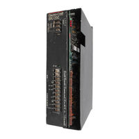
Electro-Craft BRU-500 Servo Drive Manuals
Manuals and User Guides for Electro-Craft BRU-500 Servo Drive. We have
2
Electro-Craft BRU-500 Servo Drive manuals available for free PDF download: Instruction Manual
Electro-Craft BRU-500 Instruction Manual (145 pages)
Brushless Drives
Brand:
Electro-Craft
| Category:
DC Drives
| Size: 7 MB
Table of Contents
Table of Contents
4
Section I - Introduction
10
Purpose
10
Product Description
10
Figure 1-1 BRU-500 Series Servo and Spindle Drives
10
Drive MCX:lules
11
Figure 1-2 BRU-200 Series Servo Drives
11
Power Supply Modules (BRU-500 Only)
11
Auxiliary Power Supply (BRU-500 Only)
12
Motors and Encoders
12
Transformers
12
Section 11- Specifications
13
Drive MCX:lule Specifications
13
Power Supply Module Specifications (BRU-500 Only)
14
S-Series Motor Specifications (TENV)
15
F-Series Motor Specifications (TENV)
16
-Series Motor Specifications (BRU-500 Only)
16
Encoder Specifications
17
2 Transformer Specifications
17
Maximum Power Losses
18
SECTION Ill-INSTALLATION
19
3 Mounting the Power Supply and Drive Modules
19
Power Wiring
19
Power Wiring
20
Motor Mounting and Wiring
20
External Shunt Mounting and Wiring (BRU-200 DM-30 Option Only)
20
Figure 3-1 S-Series Motor Connections
21
Figure 3-2 F-Series Motor Connections
22
Figure 3-3 I -Series Motor Connections
23
4 Drive Module Interface Connectors
24
Drive Module Interface Signal Specifications
25
Power Supply Module Interface Connector (BRU-500 Only)
29
Power Supply Module Interface Signal Specifications (BRU-500 Only)
29
Section V- Start-Up and Adjustments
30
Initial Start-Up Procedure
30
Initial Start-Up Procedure (BRU-500)
30
Initial Start-Up Procedure (BRU-200)
31
Adjustments
32
5 Power Supply Module Adjustments (BRU-500 Only)
32
Drive Module Adjustments
32
Figure 5-1 PSM Jumper Locations
34
Figure 5-2 OM Jumper and Personality Module Locations
35
Serial Interface Operation
36
Help Page
36
Operating the User Terminal
36
User Terminal Requirements
36
Figure 5-3 Serial Terminal HELP PAGE
37
Figure 5-4 Software and Personality Module Identification
37
Figure 5-5 Serial Terminal STATUS PAGE
38
Figure 5-6 Serial Terminal STATUS PAGE after Fault
38
Status Page
38
Figure 5-7 Serial Terminal SETUP PAGE (Velocity Mode)
40
Setup Page
40
Figure 5-10 Serial Terminal SETUP PAGE (Auto-Tune Mode)
41
Figure 5-8 Serial Terminal SETUP PAGE (Torque Mode)
41
Figure 5-9 Serial Terminal SETUP PAGE (Tune Mode)
41
Multi-Drop Host Mode Serial Protocol
44
Tuning Procedure
45
Using Auto-Tune Mode
45
Using Tune Mode
47
Figure 5-11 Control Block Diagrams of Operating Modes
48
Figure 5-12 Typical Small-Signal Response for Well-Tuned System
51
Figure 5-13 Personality Module Lnstallation
52
Section VI -Troubleshooting and Maintenance
53
Personality Module Installation
52
Introduction
53
LED Diagnostic Lnfonnation
53
Drive Module Leos
53
Power Supply Module Leos (BRU-500 Only)
53
Serial Unk Diagnostic Information
54
(BRU-500 Only)
55
Figure 7-1 Spindle Orient and Auxiliary Function Application (BRU-500 Only)
55
PRO-Series Controller Kit Installation Instructions
55
Section VII - Optional Accessories
55
Spindle Orient and Auxiliary Function Card Installation Instructions
55
Figure 7-2 BRU-Series Control Station
56
BRU-Series Control Station
57
Figure 7-3 BRU-Series Control Station Connection Diagram
57
RS232C/RS422 Converter
58
General Description
59
Section VIII- Application Guidelines
59
Theory of Operation
59
Torque Sharing Operation of BRU-Series Drives
59
Multiple Slave Drives
60
Set-Up Procedure
61
Tuning
61
Wiring Instructions
61
Figure 8-2 Recommended Wiring for Torque Sharing When Motors Rotate in same Direction
62
Figure 8-3 Recommended Wiring for Torque Sharing When Slave Motors Rotate Opposite of Master Motor
63
Section IX- Replacement Parts
64
8 Unequal Tor que Sharing
60
Figure 8-1 Examples of Torque Sharing Operation
60
Drive Modules
64
Power Supply Modules (BRU-500 Only)
64
Figure 9-1 Personality Module Model Number Description
65
Figure 9-2 Motor Model Number Description
65
Motors
65
Personality Modules
65
9 Cables
66
PRO-Series Kits
66
Spindle Orient and Auxiliary Function Card (BRU-500 Only)
66
Motor Mating Connectors
67
Motor Shaft Seal Kits
67
Section X- Customer Reference Drawings
68
Transformers
67
List of Drawings
68
Advertisement
Electro-Craft BRU-500 Instruction Manual (145 pages)
Brushless Drives
Brand:
Electro-Craft
| Category:
Servo Drives
| Size: 76 MB
Table of Contents
Table of Contents
7
Figure 1-1 BRU-500 Series Servo and Spindle Drives
10
Figure
10
Figure
20
Figure 5-1 PSM Jumper Locations
34
Figure 5-3 Serial Terminal HELP PAGE
37
Figure 54 Software and Personality Module Identification
37
Figure 55 Serial Terminal STATUS PAGE
38
Figure
47
Figure 7-1 Spindle Orient and Auxiliary Function Application (BRU-500 Only)
55
BRU-Series Control Station
57
Figure 8-1 Examples of Torque Sharing Operation
60
Figure 8-2 Recommended Wiring for Torque Sharing
62
When Motors Rotate in same Direction
62
Figure 8-3 Recommended Wiring for Torque Sharing When Slave
63
Motors Rotate Opposite of Master Motor
63
Figure 9-1 Personality Module Model Numberdescription
65
Figure 9-2 Motor Model Numberdescription
65
Advertisement
Related Products
Electro-Craft BRU Series
Electro-Craft BRU-200
Electro-Craft BRU-200 DM-10
Electro-Craft BRU-200 DM-20
Electro-Craft BRU-200 DM-30
Electro-Craft BRU-500 DM-25
Electro-Craft BRU-500 DM-50
Electro-Craft BSA-Series
Electro-Craft BSA-30
Electro-Craft BSA-30X
Electro-Craft Categories
Servo Drives
Amplifier
DC Drives
More Electro-Craft Manuals
Login
Sign In
OR
Sign in with Facebook
Sign in with Google
Upload manual
Upload from disk
Upload from URL