Sign In
Upload
Download
Table of Contents
Contents
Add to my manuals
Delete from my manuals
Share
URL of this page:
HTML Link:
Bookmark this page
Add
Manual will be automatically added to "My Manuals"
Print this page
×
Bookmark added
×
Added to my manuals
Manuals
Brands
Electro-Craft Manuals
DC Drives
BRU Series
Instruction manual
Electro-Craft BRU Series Instruction Manual
Brushless drives
Hide thumbs
1
2
3
Table Of Contents
4
5
6
7
8
9
10
11
12
13
14
15
16
17
18
19
20
21
22
23
24
25
26
27
28
29
30
31
32
33
34
35
36
37
38
39
40
41
42
43
44
45
46
47
48
49
50
51
52
53
54
55
56
57
58
59
60
61
62
63
64
65
66
67
68
69
70
71
72
73
74
75
76
77
78
79
80
81
82
83
84
85
86
87
88
89
90
91
92
93
94
95
96
97
98
99
100
101
102
103
104
105
106
107
108
109
110
111
112
113
114
115
116
117
118
119
120
121
122
123
124
125
126
127
128
129
130
131
132
133
134
135
136
137
138
139
140
141
142
143
144
145
page
of
145
Go
/
145
Contents
Table of Contents
Troubleshooting
Bookmarks
Table of Contents
Table of Contents
Section I - Introduction
Purpose
Product Description
Figure 1-1 BRU-500 Series Servo and Spindle Drives
Drive MCX:lules
Figure 1-2 BRU-200 Series Servo Drives
Power Supply Modules (BRU-500 Only)
Auxiliary Power Supply (BRU-500 Only)
Motors and Encoders
Transformers
Section 11- Specifications
Drive MCX:lule Specifications
Power Supply Module Specifications (BRU-500 Only)
S-Series Motor Specifications (TENV)
F-Series Motor Specifications (TENV)
-Series Motor Specifications (BRU-500 Only)
Encoder Specifications
2 Transformer Specifications
Maximum Power Losses
SECTION Ill-INSTALLATION
3 Mounting the Power Supply and Drive Modules
Power Wiring
Power Wiring
Motor Mounting and Wiring
External Shunt Mounting and Wiring (BRU-200 DM-30 Option Only)
Figure 3-1 S-Series Motor Connections
Figure 3-2 F-Series Motor Connections
Figure 3-3 I -Series Motor Connections
4 Drive Module Interface Connectors
Drive Module Interface Signal Specifications
Power Supply Module Interface Connector (BRU-500 Only)
Power Supply Module Interface Signal Specifications (BRU-500 Only)
Section V- Start-Up and Adjustments
Initial Start-Up Procedure
Initial Start-Up Procedure (BRU-500)
Initial Start-Up Procedure (BRU-200)
Adjustments
5 Power Supply Module Adjustments (BRU-500 Only)
Drive Module Adjustments
Figure 5-1 PSM Jumper Locations
Figure 5-2 OM Jumper and Personality Module Locations
Serial Interface Operation
Help Page
Operating the User Terminal
User Terminal Requirements
Figure 5-3 Serial Terminal HELP PAGE
Figure 5-4 Software and Personality Module Identification
Figure 5-5 Serial Terminal STATUS PAGE
Figure 5-6 Serial Terminal STATUS PAGE after Fault
Status Page
Figure 5-7 Serial Terminal SETUP PAGE (Velocity Mode)
Setup Page
Figure 5-10 Serial Terminal SETUP PAGE (Auto-Tune Mode)
Figure 5-8 Serial Terminal SETUP PAGE (Torque Mode)
Figure 5-9 Serial Terminal SETUP PAGE (Tune Mode)
Multi-Drop Host Mode Serial Protocol
Tuning Procedure
Using Auto-Tune Mode
Using Tune Mode
Figure 5-11 Control Block Diagrams of Operating Modes
Figure 5-12 Typical Small-Signal Response for Well-Tuned System
Figure 5-13 Personality Module Lnstallation
Section VI -Troubleshooting and Maintenance
Personality Module Installation
Introduction
LED Diagnostic Lnfonnation
Drive Module Leos
Power Supply Module Leos (BRU-500 Only)
Serial Unk Diagnostic Information
(BRU-500 Only)
Figure 7-1 Spindle Orient and Auxiliary Function Application (BRU-500 Only)
PRO-Series Controller Kit Installation Instructions
Section VII - Optional Accessories
Spindle Orient and Auxiliary Function Card Installation Instructions
Figure 7-2 BRU-Series Control Station
BRU-Series Control Station
Figure 7-3 BRU-Series Control Station Connection Diagram
RS232C/RS422 Converter
General Description
Section VIII- Application Guidelines
Theory of Operation
Torque Sharing Operation of BRU-Series Drives
Multiple Slave Drives
Set-Up Procedure
Tuning
Wiring Instructions
Figure 8-2 Recommended Wiring for Torque Sharing When Motors Rotate in same Direction
Figure 8-3 Recommended Wiring for Torque Sharing When Slave Motors Rotate Opposite of Master Motor
Section IX- Replacement Parts
8 Unequal Tor que Sharing
Figure 8-1 Examples of Torque Sharing Operation
Drive Modules
Power Supply Modules (BRU-500 Only)
Figure 9-1 Personality Module Model Number Description
Figure 9-2 Motor Model Number Description
Motors
Personality Modules
9 Cables
PRO-Series Kits
Spindle Orient and Auxiliary Function Card (BRU-500 Only)
Motor Mating Connectors
Motor Shaft Seal Kits
Section X- Customer Reference Drawings
Transformers
List of Drawings
Advertisement
Quick Links
1
Figure 1-2 Bru-200 Series Servo Drives
2
Led Diagnostic Lnfonnation
3
Section VI -Troubleshooting and Maintenance
Download this manual
BRU-200 and BRU-500
Brushless Drives
Instruction Manual
Electro-Craft
R
Servo Products
Table of
Contents
Previous
Page
Next
Page
1
2
3
4
5
Advertisement
Table of Contents
Need help?
Do you have a question about the BRU Series and is the answer not in the manual?
Ask a question
Questions and answers
Related Manuals for Electro-Craft BRU Series
Servo Drives Electro-Craft BRU-200 Instruction Manual
Brushless drives (145 pages)
Summary of Contents for Electro-Craft BRU Series
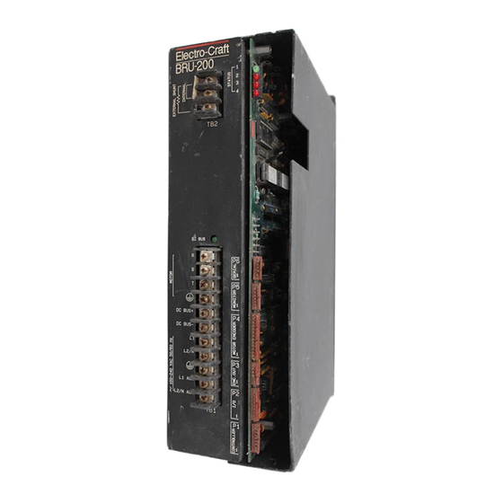
Page 1
BRU-200 and BRU-500 Brushless Drives Instruction Manual Electro-Craft Servo Products...
Page 145
BRU-200 and BRU-500 Brushless Drives Instruction Manual P/N 0013-1028-001 Revision B Reliance Motion Control, Inc. / 6950 Washington Avenue South / Eden Prairie, MN 55344 / 612-942-360 / 800-328-3983...
This manual is also suitable for:
Bru-200
Bru-500
Table of Contents
Save PDF
Print
Rename the bookmark
Delete bookmark?
Delete from my manuals?
Login
Sign In
OR
Sign in with Facebook
Sign in with Google
Upload manual
Upload from disk
Upload from URL
Need help?
Do you have a question about the BRU Series and is the answer not in the manual?
Questions and answers