Sign In
Upload
Manuals
Brands
EI Manuals
Measuring Instruments
Nexus 1272
EI Nexus 1272 Manuals
Manuals and User Guides for EI Nexus 1272. We have
1
EI Nexus 1272 manual available for free PDF download: Installation & Operation Manual
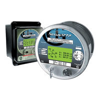
EI Nexus 1272 Installation & Operation Manual (283 pages)
High perfomance utility billing meters
Brand:
EI
| Category:
Measuring Instruments
| Size: 5 MB
Table of Contents
Safety Symbols
6
About Electro Industries/Gaugetech (EIG)
7
Table of Contents
9
Three-Phase Power Measurement
15
Three-Phase System Configurations
15
Delta Connection
18
Blondell’s Theorem and Three Phase Measurement
20
Power, Energy and Demand
22
Reactive Energy and Power Factor
26
Harmonic Distortion
28
Power Quality
31
Meter Overview
33
The Nexus 1262/1272 Multi-Parameter Revenue Meter
33
Accu-Measure Technology - Theory of Operation
33
Advanced Measurement Functionality
36
Advanced Revenue Billing Capability
36
Communications and I/O Capabilities
38
Transformer Loss Compensation
38
Standard Communications
38
Standard Internal I/O
39
Upgradeable External I/O
39
External I/O Modules
39
Display Screens
40
Additional Switches
40
External I/O Modules
40
1262/1272 Meter Forms
41
Switchboard Meter
41
Nexus 1262/1272 Meter Accuracy
42
1262/1272 Meter Specifications Overview
42
Voltage (AC)
43
External Power Supply Options
43
Isolation
43
Clock Timing
45
Environmental (Temperature Specifications to Indirect Light)
45
Security
45
1262/1272 Meter Logging Specifications
47
DNP V3.00 Level 2
47
Operating Instructions
49
Nameplate Information
49
Power Supply
51
Basic Operation
52
Switches and Indicators
52
Optical Port
53
Test Pulse
53
Phase Indicator
53
LCD Display Information
54
Mode Details
54
Display Configurator
55
Base Programmable Display
55
Low Battery
55
Test Mode
55
Initial Display Screens
56
Backlight
56
Finding Your Display’s Firmware Versions
57
Nexus 1262/1272 Programmable Display Navigation Map
58
Using the Display Configurator
59
To Access the Display Configurator's Programming Screens
59
Power and Energy Display Tab
73
Miscellaneous Tab
74
Using the Base Programmable Display
76
Programming the Base Programmable Display
76
Pre-Defined Display Screens
78
Performing Meter Testing
83
Testing Tools
84
Test Pulse LED
84
To Program the Test Pulse LED
84
Meter Test Pulse and Test Button Location
84
LCD Display
85
Entering Test Mode
86
Using Test Mode
86
Test Mode Displayed Data and Pulse Source
86
Test Mode Details
87
Test Mode Preset Accumulators
87
Setting Test Mode Preset Accumulators
88
Exiting Test Mode
90
Test Mode Button
90
Test Mode Time-Out Timer
90
If the Meter Does Not Recognize Measurable Load
90
Serial Communication Wiring
93
Communication Overview
93
A7Z Instructions
95
A9U Instructions
96
RS485 Serial Communication
97
RS485 Wiring Fundamentals
97
Using the Unicom 2500
99
RJ11 (Telephone Line) Connection
101
RJ45 Connection
101
Modem/Ethernet Connection
101
RS485 Connection
102
Communication Ports on the I/O Modules
104
RS485 Connection—Meter to I/O Modules
104
Steps to Determine Power Needed
107
Programming Modems for Remote Communication
109
Selected Modem Strings
110
High Speed Inputs Connection
110
IRIG-B Connections
111
Connection
111
Installation
112
Troubleshooting Tip
113
Time Synchronization Alternatives
114
Line Frequency Clock Synchronization
114
Internal Clock Crystal
114
DNP Time Synchronization
114
INP2 Internal Modem with Dial-In/Dial-Out Option
115
Hardware Overview
115
Hardware Connection
115
Dial-In Function
116
Dial-Out Function
116
INP200 Onboard Ethernet
118
Advanced Settings
121
INP202 Ethernet/Modem Combination
123
Factory Settings
125
Hardware Installation
127
Mounting the Nexus Socket Meter
127
Installation Summary
127
Socket Meter Mounting Dimensions
127
Socket Meter Rear View Showing Cables
129
Socket Meter Mounted in A-Base Front View
130
Cable Color Key
131
Socket Meter in A-Base Side View
131
Internal Battery Installation and Maintenance
133
Meter Without Internal Shroud
134
Battery Holder Detail
135
Battery Safety and Disposal
136
Mounting the Optional External Displays
136
Legacy P40N Dimensions
137
P40N+ Front and Side Dimensions
137
P40N/P40N+ ANSI Mounting
138
Mounting the Nexus External I/O Modules
139
I/O Modules Mounting Diagram, Overhead View
139
Single I/O Module with Mounting Brackets
140
I/O Modules Mounting Dimensions, Front View
140
I/O Modules with PSIO Power Supply
141
I/O Module Wiring Detail
141
Time-Of-Use Function
143
Meter’s TOU Calendar
143
TOU Frozen and Active Registers
144
Updating, Retrieving and Replacing TOU Calendars
144
Daylight Savings and Demand
145
Transformer Line Loss Compensation
147
Loss Compensation in Three Element Installations
151
Three-Element Loss Compensation Worksheet
152
Meter/Installation Data
154
Base Conversion Factors
154
Calculate Load Loss Values
157
Using the External Displays
159
P40N/P40N+ LED External Display
159
Serial Port
163
Dynamic Readings Mode
164
Navigation Map of Dynamic Readings Mode
168
Nexus Information Mode
169
Navigation Map of Nexus Information Mode
171
Display Features Mode
172
Group 1: Reset Max/Min
172
Group 2: Reset Energy
172
Navigation Map of Display Features Mode
174
Optional P40N+ LED External Remote Display Specifications
175
Port Overview
178
Four Analog Outputs
178
Eight Analog Outputs
178
I/O Module Installation
179
Power Source for I/O Modules
179
Power Flow from PSIO to I/O Module
179
Using the PSIO with Multiple I/O Modules
180
PSIO Side and Top Labels
180
PSIO Used with Multiple I/O Modules
180
Steps for Attaching Multiple I/O Modules
181
Mounting the Brackets on a DIN Rail
182
To Use the DIN Rail Mounting Clips
182
Factory Settings and Reset Button
183
Detail of DIN Rail Mounting Clip
183
Reset Button
183
Analog Transducer Signal Output Modules
184
Analog Transducer Signal Output Module Specifications
184
Normal Mode
185
Analog Input Modules
186
Analog Input Module Specifications
186
Digital Dry Contact Relay Output (Form C) Module
188
Communication
189
Digital Solid State Pulse Output (KYZ) Module
190
Digital Solid State Pulse Output Module Specifications
190
Digital Status Input Module
193
Digital Status Input Module Specifications
193
Electrical Installation
195
Considerations When Installing Meters
195
Blade Configuration for Forms 9S, 36S, and 45S
199
Form 9S & 36S Base with Knock out Holes
199
Form 45S Base with Knock out Holes
199
Wiring Diagrams
200
9S Meter Mounted in S/A Adapter
218
Switchboard Meter
219
Switchboard Meter Dimensions, Front
219
Labels
220
Specifications and Dimensions
221
Sample of Switchboard Options Label
221
Switchboard Meter Dimensions, Side
223
Switchboard Meter Cutout
224
Switchboard Case Front Showing 4 Screw Holes
226
Switchboard Meter Back Showing Connectors
226
Switchboard Meter Configurations
227
Z Transformer Rated Wye, no Pts, 3 Cts
229
9Z Transformer Rated Wye, 3 Pts, 3 Cts
230
9Z Transformer Rated 4-Wire Delta, no Pts, 3 Cts
231
9Z Transformer Rated 4-Wire Delta, 3 Pts, 3 Cts
232
9Z Transformer Rated 3-Wire Delta, no Pts, 2 Cts
233
9Z Transformer Rated 3-Wire Delta, 2 Pts, 2 Cts
234
36Z 2.5 Element Wye, no Pts, 3 Cts
237
36Z 2.5 Element Wye, 2 Pts, 3 Cts
238
Delta, 3-Wire, 2 Pts, 3 Cts
239
Delta, 3-Wire, no Pts, 3 Cts
240
E137370 Retrofit Panel - S1 to M1 Case Retrofit
241
To Use the Panel
241
Attaching the Panel and Inserting the Meter
241
E137370 Retrofit Panel Dimensions
242
Side Dimensions
242
Front Dimensions
242
Meter Calculations
243
Measurements and Calculations
243
Demand Integrators
249
Block (Fixed) Window Demand
249
Rolling (Sliding) Window Demand
249
Thermal Demand
250
Predictive Window Demand
250
EN50160/IEC61000-4-15 Flicker
253
Theory of Operation
253
Measurement Procedure
255
Flicker Setup
256
Data Available
256
Flicker Polling Screen
257
Main Screen
257
Time
258
Status
258
Frequency
258
Base Voltage
258
Instantaneous Readings
259
Short Term Readings
259
Long Term Readings
260
Logging
261
Polling through a Communication Port
261
Log Viewer
261
Performance Notes
262
Calculating Values
263
Excel Spreadsheet with Example Numbers
263
Blade Configuration for Forms 9S, 36S and 45S
269
Blade Configuration Drawings
270
Glossary
271
Advertisement
Advertisement
Related Products
EI Nexus 1250
EI Nexus 1252
EI Nexus 1262
EI Categories
Security System
Smoke Alarm
Measuring Instruments
Gateway
Control Unit
More EI Manuals
Login
Sign In
OR
Sign in with Facebook
Sign in with Google
Upload manual
Upload from disk
Upload from URL