Table of Contents
Advertisement
Quick Links
Advertisement
Table of Contents

Related Manuals for EI Nexus 1262

Summary of Contents for EI Nexus 1262
- Page 3 ® Nexus 1262/1272 Meter Installation and Operation Manual Version 1.21 Published by: Electro Industries/GaugeTech 1800 Shames Drive Westbury, NY 11590 All rights reserved. No part of this publication may be reproduced or transmitted in any form or by any means, electronic or mechanical, including photocopying, record- ing, or information storage or retrieval systems or any future forms of duplication, for any purpose other than the purchaser's use, without the expressed written permission of Electro Industries/GaugeTech.
- Page 4 This page intentionally left blank. Electro Industries/GaugeTech Electro Industries/GaugeTech E151701 The Leader In Power Monitoring and Smart Grid Solutions The Leader In Power Monitoring and Smart Grid Solutions...
- Page 5 Customer Service and Support Customer support is available 9:00 am to 4:30 pm, Eastern Standard Time, Monday through Friday. Please have the model, serial number and a detailed problem descrip- tion available. If the problem concerns a particular reading, please have all meter readings available.
-
Page 6: Safety Symbols
Use of Product for Protection Our products are not to be used for primary over-current protection. Any protection feature in our products is to be used for alarm or secondary protection only. Statement of Calibration Our instruments are inspected and tested in accordance with specifications published by Electro Industries/GaugeTech. - Page 7 This symbol indicates the field wiring terminal that must be connected to earth ground before operating the meter, which protects against electrical shock in case of a fault condition. Ce symbole indique que la borne de pose des canalisations in-situ qui doit être bran- chée dans la mise à...
- Page 8 This page intentionally left blank. Electro Industries/GaugeTech Electro Industries/GaugeTech E151701 The Leader In Power Monitoring and Smart Grid Solutions The Leader In Power Monitoring and Smart Grid Solutions...
- Page 9 Table of Contents 1:Three-Phase Power Measurement 2: Meter Overview 3: Operating Instructions Electro Industries/GaugeTech Electro Industries/GaugeTech The Leader In Power Monitoring and Smart Grid Solutions The Leader In Power Monitoring and Smart Grid Solutions...
- Page 10 4: Performing Meter Testing 5: Serial Communication Wiring Electro Industries/GaugeTech Electro Industries/GaugeTech The Leader In Power Monitoring and Smart Grid Solutions The Leader In Power Monitoring and Smart Grid Solutions...
- Page 11 6: Hardware Installation 7: Time-of-Use Function Electro Industries/GaugeTech Electro Industries/GaugeTech The Leader In Power Monitoring and Smart Grid Solutions The Leader In Power Monitoring and Smart Grid Solutions...
- Page 12 8: Transformer Loss Compensation 9: Using the External Displays 10: External I/O Modules 10-1 Electro Industries/GaugeTech Electro Industries/GaugeTech The Leader In Power Monitoring and Smart Grid Solutions The Leader In Power Monitoring and Smart Grid Solutions...
- Page 13 11: Electrical Installation 11-1 Considerations when Installing Meters 11-1 11.2: Blade Configuration for for Forms 9S, 36S, and 45S 11-5 11.3: 12: Switchboard Meter 12-1 12.6: E137370 S1 to M1 Retrofit Panel 12-23 13: Meter Calculations 13-1 14: EN50160/IEC61000-4-15 Flicker 14-1 Electro Industries/GaugeTech Electro Industries/GaugeTech...
- Page 14 B: Blade Configuration for Forms 9S, 36S and 45S Glossary GL-1 Electro Industries/GaugeTech Electro Industries/GaugeTech The Leader In Power Monitoring and Smart Grid Solutions The Leader In Power Monitoring and Smart Grid Solutions...
-
Page 15: Three-Phase Power Measurement
1:Three-Phase Power Measurement 1.1: Three-Phase System Configurations 1.1.1: Wye Connection Electro Industries/GaugeTech The Leader In Power Monitoring and Smart Grid Solutions... - Page 16 Phase 2 Phase 1 Phase 3 Electro Industries/GaugeTech The Leader In Power Monitoring and Smart Grid Solutions...
- Page 17 Phase to Ground Voltage Phase to Phase Voltage Electro Industries/GaugeTech The Leader In Power Monitoring and Smart Grid Solutions...
- Page 18 1.1.2: Delta Connection Phase 3 Phase 2 Phase 1 Electro Industries/GaugeTech The Leader In Power Monitoring and Smart Grid Solutions...
- Page 19 Electro Industries/GaugeTech The Leader In Power Monitoring and Smart Grid Solutions...
- Page 20 1.1.3: Blondell’s Theorem and Three Phase Measurement Electro Industries/GaugeTech The Leader In Power Monitoring and Smart Grid Solutions...
- Page 21 Phase B Phase C Node "n" Phase A Electro Industries/GaugeTech The Leader In Power Monitoring and Smart Grid Solutions...
- Page 22 1.2: Power, Energy and Demand Electro Industries/GaugeTech The Leader In Power Monitoring and Smart Grid Solutions...
- Page 23 Time (minutes) Electro Industries/GaugeTech The Leader In Power Monitoring and Smart Grid Solutions...
- Page 24 Time Accumulated Power Energy Interval Energy (kW) (kWh) (minute) (kWh) Electro Industries/GaugeTech The Leader In Power Monitoring and Smart Grid Solutions...
- Page 25 Intervals (15 mins.) Electro Industries/GaugeTech The Leader In Power Monitoring and Smart Grid Solutions...
- Page 26 1.3: Reactive Energy and Power Factor Electro Industries/GaugeTech The Leader In Power Monitoring and Smart Grid Solutions...
- Page 27 Electro Industries/GaugeTech The Leader In Power Monitoring and Smart Grid Solutions...
- Page 28 1.4: Harmonic Distortion 1000 Time – 500 – 1000 Electro Industries/GaugeTech The Leader In Power Monitoring and Smart Grid Solutions...
- Page 29 1500 1000 –500 –1000 –1500 1000 Time 3rd harmonic 5th harmonic – 500 7th harmonic Total fundamental Electro Industries/GaugeTech The Leader In Power Monitoring and Smart Grid Solutions...
- Page 30 Electro Industries/GaugeTech The Leader In Power Monitoring and Smart Grid Solutions...
- Page 31 1.5: Power Quality Electro Industries/GaugeTech The Leader In Power Monitoring and Smart Grid Solutions...
- Page 32 Cause Disturbance Type Source Electro Industries/GaugeTech The Leader In Power Monitoring and Smart Grid Solutions...
-
Page 33: Meter Overview
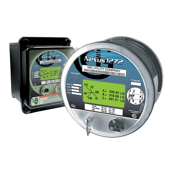
2: Meter Overview 2: Meter Overview 2.1: The Nexus® 1262/1272 Multi-parameter Revenue Meter The Nexus® 1262/1272 transformer-rated, polyphase revenue meter is a unique collection of metering technologies designed to fulfill advanced metering require- ments. It provides high-accuracy power and energy measurements of Voltage, current and all power values, data logging and power quality recording. - Page 34 2: Meter Overview ® Figure 2.1: How the Nexus 1262/1272 Meter Processes Inputs The digitized signals are then passed to the appropriate processor. Real-time measurements are calculated in one processor and made available for meter readings and historical logs. A separate processor performs waveform recording. Calculated data and logs are stored in memory for delivery to displays, external systems and download processes.
- Page 35 2: Meter Overview Eight status channels provide input of status or pulse signals. Status inputs are date/ time stamped to the nearest millisecond and placed in the event log. Pulse inputs are multiplied by a user-supplied factor and accumulated in reading registers. These accumulated values can also be totalized.
- Page 36 2: Meter Overview 2.3: Advanced Measurement Functionality 2.3.1: Advanced Revenue Billing Capability The Nexus® 1262/1272 device is a full four-quadrant power and energy meter with accuracy of within 0.06% of reading at full load unity PF. Energy measurements include: kWh Delivered & Received, kVARh Delivered & Received, kVAh, kVARh, kWh in each quadrant and Total kVAh.
- Page 37 2: Meter Overview • Individual accumulating registers • 4 totalizing registers • Totalization with Nexus® meter kWh readings Multiple Demand Windows The Nexus® 1262/1272 meter simultaneously monitors four demand structures. The unit offers: • Block Window Demand • Rolling Window Demand •...
-
Page 38: Transformer Loss Compensation
2: Meter Overview Transformer Loss Compensation Transformer Loss Compensation adjusts for both copper and iron losses with a simple user setup. 2.3.2: Communications and I/O Capabilities The Nexus® 1262/1272 meter features advanced communication which utilizes multiple Com ports using open protocols. The meter’s multi-port design allows multi- ple communication connections simultaneously. -
Page 39: External I/O Modules
2: Meter Overview Standard Internal I/O Extensive I/O capability is available in conjunction with all metering functions: • IRIG-B Time Synchronizing to GPS to 1 millisecond resolution • 8 High-Speed Status Inputs for status detect or of load aggregation/universal metering inputs •... - Page 40 2: Meter Overview 2.3.3: Display Screens The Nexus® 1262/1272 meter features a built-in graphical back-lit FSTN LCD display with extended temperature Voltage compensation. This allows you to view energy data and to gather circuit diagnostic data such as Voltage, current, harmonics and phasor information.
-
Page 41: Switchboard Meter
2: Meter Overview 2.4: Nexus® 1262/1272 Meter Forms • The Nexus® 1262/1272 Socket meter offers three supported S-Based meter forms based on the rated Voltage and hookup required by the user. Below are the form specifications. Table 1: Nexus 1262/1272 Meter Forms ®... - Page 42 2: Meter Overview 2.5: Nexus® 1262/1272 Meter Accuracy Table 2: Nexus 1262/1272 Meter Accuracy ® Value Accuracy Voltage 0.02% Current 0.05% Frequency 0.001Hz 0.06% Wh@1.0PF 0.06% Wh@0.5PF 0.10% 0.10% 0.10% 0.10% 2.6: Nexus® 1262/1272 Meter Specifications Overview Sense Inputs Current (AC) •...
- Page 43 2: Meter Overview Voltage (AC) • Blade powered unit, standard Voltage (Option S): 480V max Phase to Reference (Va, Vb, Vc, to VRef), burden total 12V max (including power supply); 600V max Phase to Phase (Va to Vb, Vb to Vc, Vc to Va) •...
- Page 44 2: Meter Overview • 8-Channel Sample and Hold Memory • All meter setup parameters, measurements and logs contained in nonvolatile RAM Standard Communications • LCD display • ANSI Type 2 Optical port • Two RS485 serial ports • Modbus® RTU, Modbus ASCII and DNP 3.0 protocols •...
- Page 45 2: Meter Overview • Continuous Load Current: 120mA • Peak Load Current: 350mA (10ms) • Off-State Leakage Current @350Vdc: 1: A • Opto Isolation: 3750V rms (60 Hz, 1 min) Clock Timing • IRIG-B input for synchronizing to external GPS clock signal - accuracy better than 1msec per month •...
- Page 46 2: Meter Overview Internal Battery • Panasonic BR3032 3V Lithium Battery (or equivalent) maintains NVRAM and time during outages. Modem Battery • 3V Lithium Battery with custom leads and velcro mounting maintains Dial-Back feature during outages. Call factory for replacement battery - the part # is BAT1. IRIG-B Port Impedance •...
- Page 47 2: Meter Overview 2.7: Nexus® 1262/1272 Meter Logging Specifications Table 3: CBEMA Event Wave- Input Historical Historical Flicker Output System Model Memory form Log 1* Log 2* Log** Log** Events** ITIC** Log*** 1272 Standard 85 Days 133 Days 1024 1536 1024 1024 1272...
- Page 48 2: Meter Overview This page intentionally left blank. Electro Industries/GaugeTech E151701 2-16 The Leader In Power Monitoring and Smart Grid Solutions...
-
Page 49: Operating Instructions
3: Operating Instructions 3.1: Nameplate Information Electro Industries/GaugeTech Electro Industries/GaugeTech The Leader In Power Monitoring and Smart Grid Solutions The Leader In Power Monitoring and Smart Grid Solutions... - Page 50 Model: NEXUS 1272-S-SWB2-20-60-SE-INP202 Serial#: 114-0074880532 Memory: 2 Meg Class: Freq.: 60 Hz KYZ Out: Opt. Comm: Ethernet/Modem Combo Power Supply: Std. Ext 102-275V AC/DC Memory (1272): Memory (1262): Communication Options: Electro Industries/GaugeTech Electro Industries/GaugeTech The Leader In Power Monitoring and Smart Grid Solutions The Leader In Power Monitoring and Smart Grid Solutions...
-
Page 51: Power Supply
Case Style: Power Supply: EIG Number - Model Number plus Option Numbers Electro Industries/GaugeTech Electro Industries/GaugeTech The Leader In Power Monitoring and Smart Grid Solutions The Leader In Power Monitoring and Smart Grid Solutions... - Page 52 3.2: Basic Operation Switches and Indicators Mode Reset Test Electro Industries/GaugeTech Electro Industries/GaugeTech The Leader In Power Monitoring and Smart Grid Solutions The Leader In Power Monitoring and Smart Grid Solutions...
- Page 53 Optical Port Test Pulse Phase Indicator that phase has voltage but no current, and is blank if that phase has no voltage or current Electro Industries/GaugeTech Electro Industries/GaugeTech The Leader In Power Monitoring and Smart Grid Solutions The Leader In Power Monitoring and Smart Grid Solutions...
- Page 54 3.3: LCD Display Information Mode Details Electro Industries/GaugeTech Electro Industries/GaugeTech The Leader In Power Monitoring and Smart Grid Solutions The Leader In Power Monitoring and Smart Grid Solutions...
-
Page 55: Test Mode
Display Configurator Base Programmable Display NOTE: Low Battery Test Mode Electro Industries/GaugeTech Electro Industries/GaugeTech The Leader In Power Monitoring and Smart Grid Solutions The Leader In Power Monitoring and Smart Grid Solutions... - Page 56 Initial Display Screens Backlight Electro Industries/GaugeTech Electro Industries/GaugeTech The Leader In Power Monitoring and Smart Grid Solutions The Leader In Power Monitoring and Smart Grid Solutions...
- Page 57 3.3.1: Finding Your Display’s Firmware Versions Profile Revenue and Energy Settings>Display Configuration Electro Industries/GaugeTech Electro Industries/GaugeTech The Leader In Power Monitoring and Smart Grid Solutions The Leader In Power Monitoring and Smart Grid Solutions...
- Page 58 3.4: Nexus 1262/1272 Programmable Display Navigation Map Electro Industries/GaugeTech Electro Industries/GaugeTech The Leader In Power Monitoring and Smart Grid Solutions The Leader In Power Monitoring and Smart Grid Solutions...
- Page 59 3.5: Using the Display Configurator IMPORTANT! Modus Protocol and Register Map for Nexus 1252/1262/1272 Meters ® To access the Display Configurator's programming screens Profile Electro Industries/GaugeTech Electro Industries/GaugeTech The Leader In Power Monitoring and Smart Grid Solutions The Leader In Power Monitoring and Smart Grid Solutions...
- Page 60 Display Configuration Electro Industries/GaugeTech Electro Industries/GaugeTech The Leader In Power Monitoring and Smart Grid Solutions The Leader In Power Monitoring and Smart Grid Solutions...
- Page 61 Display screens available for assignment to View modes Right-click on a screen to assign it to View mode or to copy it Buttons that View Mode let you: Columns Create custom display screens, Edit display screens, or Remove display screens from the available Buttons that let you: Change the order of display screens screens list...
- Page 62 Move Up Move Down Remove Create Creating a Custom Display Screen NOTE Edit Creating a Custom Display Screen Edit Editing a Pre-defined Dis- play Screen Electro Industries/GaugeTech Electro Industries/GaugeTech The Leader In Power Monitoring and Smart Grid Solutions The Leader In Power Monitoring and Smart Grid Solutions...
- Page 63 Create New Screen Based on Selected Screen Editing a Pre-defined Display Screen Remove Create Click to create custom screen Electro Industries/GaugeTech Electro Industries/GaugeTech The Leader In Power Monitoring and Smart Grid Solutions The Leader In Power Monitoring and Smart Grid Solutions...
- Page 64 User defined You can change this number Select number of screen items OR 1 Demand,1 Timestamp The fields in These Screen Layout fields are are determined for Modbus by the number Information of items you select These fields are for multiplier setup These fields...
- Page 65 Custom Screen with 3 Item Fields The information for these fields comes Display screen from the meter’s label fields Modbus Register Item entry fields This is where you click here to can specify a Modbus enter the multiplier for your Register containing data the item...
- Page 66 Example Nexus 1252/1262/1272 Meter Modbus Manual Electro Industries/GaugeTech Electro Industries/GaugeTech The Leader In Power Monitoring and Smart Grid Solutions The Leader In Power Monitoring and Smart Grid Solutions...
- Page 67 IMPORTANT! All of the data items you select must be the same Modbus type Example: 1 Cycle Block 00090-00093 1 cycle Block Time Stamp 12/31/9999 23:59:59:99 10 msec 00094-00095 1 cycle Phase A-N Voltage +65536 V1 / D V 1/65536 V Update Nexus 1252/1262/1272 Meter Modbus Manual...
- Page 68 3.5: Type F5 Secondary 1 Cycle RMS Voltage or Current Length: 2 Registers (4 bytes) Range: +1,048,576 V 2 / 0 V 2 or +65536 I2 / 0 I2(1262 or 1272) Unit: 1/4906 V secondary or 1/65536 A2 secondary (1262 or 1272) These registers together are a four-byte unsigned integer.
- Page 69 Table 1: Entry fields Possible entries Save Upload Cancel without saving any changes Electro Industries/GaugeTech Electro Industries/GaugeTech The Leader In Power Monitoring and Smart Grid Solutions The Leader In Power Monitoring and Smart Grid Solutions...
- Page 70 NOTE: Table 2: Pre-defined LCD Screen Number Description Editing Options (Default Value) Edit Create a new screen based on selected s creen Electro Industries/GaugeTech Electro Industries/GaugeTech The Leader In Power Monitoring and Smart Grid Solutions The Leader In Power Monitoring and Smart Grid Solutions...
- Page 71 NOTES: Electro Industries/GaugeTech Electro Industries/GaugeTech The Leader In Power Monitoring and Smart Grid Solutions The Leader In Power Monitoring and Smart Grid Solutions...
- Page 72 You can change the screen number You can enter a screen label Save Upload Cancel without saving any changes Electro Industries/GaugeTech Electro Industries/GaugeTech The Leader In Power Monitoring and Smart Grid Solutions The Leader In Power Monitoring and Smart Grid Solutions...
- Page 73 Power and Energy Display Tab NOTES: Electro Industries/GaugeTech Electro Industries/GaugeTech The Leader In Power Monitoring and Smart Grid Solutions The Leader In Power Monitoring and Smart Grid Solutions...
- Page 74 Miscellaneous Tab Electro Industries/GaugeTech Electro Industries/GaugeTech The Leader In Power Monitoring and Smart Grid Solutions The Leader In Power Monitoring and Smart Grid Solutions...
- Page 75 When you have finished programming the Device Display Programmable Settings Screen Update Display Retrieve from Display Cancel Save Update Display Electro Industries/GaugeTech Electro Industries/GaugeTech The Leader In Power Monitoring and Smart Grid Solutions The Leader In Power Monitoring and Smart Grid Solutions...
- Page 76 3.6: Using the Base Programmable Display Programming the Base Programmable Display Profile Display Configuration except for Electro Industries/GaugeTech Electro Industries/GaugeTech The Leader In Power Monitoring and Smart Grid Solutions The Leader In Power Monitoring and Smart Grid Solutions...
- Page 77 NOTE: Electro Industries/GaugeTech Electro Industries/GaugeTech The Leader In Power Monitoring and Smart Grid Solutions The Leader In Power Monitoring and Smart Grid Solutions...
- Page 78 3.6.1: Pre-Defined Display Screens Screen Number Screen Name DEL 43089263 REC 71323159 06/16/2011 3:50:44 Norm ABC ROLLING DEMAND 502.3 3:07:2003 2:07:09 06/16/2011 3:50:44 Norm ABC Electro Industries/GaugeTech Electro Industries/GaugeTech The Leader In Power Monitoring and Smart Grid Solutions The Leader In Power Monitoring and Smart Grid Solutions...
- Page 79 la HARMONICS 003.67 06/18/2011 12:22:44 CDM ABC VC IC 30.02 LG 16.03 LG 17.01 LG Electro Industries/GaugeTech Electro Industries/GaugeTech The Leader In Power Monitoring and Smart Grid Solutions The Leader In Power Monitoring and Smart Grid Solutions...
- Page 80 Electro Industries/GaugeTech Electro Industries/GaugeTech The Leader In Power Monitoring and Smart Grid Solutions The Leader In Power Monitoring and Smart Grid Solutions...
- Page 81 Electro Industries/GaugeTech Electro Industries/GaugeTech The Leader In Power Monitoring and Smart Grid Solutions The Leader In Power Monitoring and Smart Grid Solutions...
- Page 82 Electro Industries/GaugeTech Electro Industries/GaugeTech The Leader In Power Monitoring and Smart Grid Solutions The Leader In Power Monitoring and Smart Grid Solutions...
- Page 83 4: Performing Meter Testing 4: Performing Meter Testing The information contained within this chapter is intended to be an aid to qualified metering personnel. It is not intended to replace the extensive training necessary to install or remove meters from service. Any work on or near energized meters, meter sockets or other metering equipment presents the danger of electrical shock, personal injury or death.
- Page 84 4: Performing Meter Testing 4.1: Testing Tools The Nexus® 1262 and 1272 meters are equipped with a light-emitting diode (LED) for calibration and a liquid crystal display with test screens. These two standard features provide user interface and equipment interface points for meter testing. Infrared Test Pulse Test Button...
- Page 85 4: Performing Meter Testing a. Assigned Channel - choose from settings. b. Watt-hour per Pulse - enter the value in the secondary. c. Pulse Width - set from 5ms to 635ms. d. Mode - select to enable or disable. e. Form - select between Form A and Form C. 2.
- Page 86 4: Performing Meter Testing 4.2.1: Entering Test Mode To enter Test Mode, you must bypass the meter’s security system. In most instances, this requires you to remove power from the meter, break the meter seal and remove the Lexan cover, and then repower the meter. 4.2.2: Using Test Mode The same selected measurement profile quantities (data accumulations) that are calculated during normal operation are calculated in Test Mode.
- Page 87 4: Performing Meter Testing Test Mode Details The Reset Button (R) is next to the Test Button (T). Initiate a Test Mode Reset by pressing and releasing the Reset Button while in Test Mode. A Test Mode Reset causes all test quantities to be reset to zero and a new block interval to be started. The item displayed when the reset occurred remains in the display but the value is initialized.
- Page 88 4: Performing Meter Testing Setting Test Mode Preset Accumulators 1. From Communicator EXT’s Main screen, select Tools>Test Mode>Preset Accumulators. You will see the screen shown below. 2. Click Tabs at the top of the screens to access the individual screens. •...
- Page 89 4: Performing Meter Testing • Q Hours • I & V Squared T Accumulators • Cumulative Demand (Secondary) • Uncompensated Energy Examples of some of the screens are shown below. 4. Click the Preset Boxes for the values you want to set. 5.
- Page 90 4: Performing Meter Testing 4.2.4: Exiting Test Mode Exit Test Mode in one of the following three ways: • Press and hold the Test Button for more than 3 seconds. • Use the Test Mode Time-out Timer, if no load is present. •...
- Page 91 4: Performing Meter Testing as the current subinterval are zeroed. Upon returning to Normal operating mode, a TOU meter or Demand meter with load profiling completes the time remaining in the current partial subinterval so that subsequent subintervals are synchronized with the hourly boundary.
- Page 92 4: Performing Meter Testing This page intentionally left blank. Electro Industries/GaugeTech Electro Industries/GaugeTech E151701 4 - 10 The Leader In Power Monitoring and Smart Grid Solutions The Leader In Power Monitoring and Smart Grid Solutions...
- Page 93 5: Serial Communication Wiring 5.1: Communication Overview Optical Port to RS232 Communication Interface (e.g., A7Z) Optical Port RS232 50 Feet RS485 RS232 4000 Feet 50 Feet RS485/232 Converter (Unicom 2500) RS485 RS232 4000 Feet 50 Feet RS485/232 Converter (Modem Manager) Electro Industries/GaugeTech Electro Industries/GaugeTech The Leader In Power Monitoring and Smart Grid Solutions...
- Page 94 Optical Port 5.2: Communicating to the Meter through the ANSI Type II Optical Port Electro Industries/GaugeTech Electro Industries/GaugeTech The Leader In Power Monitoring and Smart Grid Solutions The Leader In Power Monitoring and Smart Grid Solutions...
- Page 95 A7Z Instructions: Electro Industries/GaugeTech Electro Industries/GaugeTech The Leader In Power Monitoring and Smart Grid Solutions The Leader In Power Monitoring and Smart Grid Solutions...
- Page 96 A9U Instructions: Electro Industries/GaugeTech Electro Industries/GaugeTech The Leader In Power Monitoring and Smart Grid Solutions The Leader In Power Monitoring and Smart Grid Solutions...
- Page 97 5.3: RS485 Serial Communication 5.3.1: RS485 Wiring Fundamentals - (Port 1 and Port 4) From other RS485 device Connect : Nexus • (−) to (−) 1262/1272 • (+) to (+) RS485 Port • Shield(SH) to Shield(SH) NOTES on RS485 Connections: Electro Industries/GaugeTech Electro Industries/GaugeTech The Leader In Power Monitoring and Smart Grid Solutions...
- Page 98 Master device Last Slave device N Slave device 1 Slave device 2 Twisted pair, shielded (SH) cable Twisted pair, shielded (SH) cable Twisted pair, shielded (SH) cable Earth Connection, preferably at single location Electro Industries/GaugeTech Electro Industries/GaugeTech The Leader In Power Monitoring and Smart Grid Solutions The Leader In Power Monitoring and Smart Grid Solutions...
- Page 99 Slave device 1 Long stub results “T” connection that can cause interference problem! Master device Last Slave device N Slave device 2 Twisted pair, shielded (SH) cable Twisted pair, shielded (SH) cable Twisted pair, shielded (SH) cable Earth Connection, preferably at single location Twisted pair, shielded (SH) cable Twisted pair, shielded (SH) cable...
- Page 100 RS232 Port UNICOM 2500 TX(-) RX(-) TX(+) RX(+) SH Jumpers: Short TX(-) to RX(-) becomes (-) signal Short TX(+) to RX(+) becomes (+) signal Meter’s RS485 Port Electro Industries/GaugeTech Electro Industries/GaugeTech The Leader In Power Monitoring and Smart Grid Solutions The Leader In Power Monitoring and Smart Grid Solutions...
- Page 101 5.3.3: RJ11 (Telephone Line) Connection—Meter with INP2 (Internal Modem with Dial In/Dial Out) Option 5.3.4: RJ45 Connection—Meter with INP200 (10/100BaseT) Option 5.3.5: Modem/Ethernet Connection—Meter with INP202 (Combo Card) Option Electro Industries/GaugeTech Electro Industries/GaugeTech The Leader In Power Monitoring and Smart Grid Solutions The Leader In Power Monitoring and Smart Grid Solutions...
- Page 102 5.3.6: RS485 Connection - Meter to the P40N/P40N+/P41N+/P43N+ LED Display Electro Industries/GaugeTech Electro Industries/GaugeTech The Leader In Power Monitoring and Smart Grid Solutions The Leader In Power Monitoring and Smart Grid Solutions...
- Page 103 NOTE: - V + R T * External Power Source PB1 or other P40N+ LED Display, Back View R T * * See Note on page 5-5. **Please refer to Cable Color P40N LED Display, Back View Key, page 6-4, and second bullet, page 5-5.
- Page 104 5.3.7: Communication Ports on the I/O Modules Female RS485 Side Port I/O Port (Size and Pin Male RS485 Configuration Vary) Side Port Female RS485 Side Port Male RS485 Side Port I/O Port 5.3.8: RS485 Connection—Meter to I/O Modules Electro Industries/GaugeTech Electro Industries/GaugeTech The Leader In Power Monitoring and Smart Grid Solutions The Leader In Power Monitoring and Smart Grid Solutions...
- Page 105 NOTES: Electro Industries/GaugeTech Electro Industries/GaugeTech The Leader In Power Monitoring and Smart Grid Solutions The Leader In Power Monitoring and Smart Grid Solutions...
- Page 106 Male Side Port on I/O Module R T= 120 Ohms R T= 120 Ohms Meter’s Port 4 Electro Industries/GaugeTech Electro Industries/GaugeTech The Leader In Power Monitoring and Smart Grid Solutions The Leader In Power Monitoring and Smart Grid Solutions...
- Page 107 5.3.9: Steps to Determine Power Needed I/O Module Factory Settings and VA Ratings Model# Module Address VA Rating Electro Industries/GaugeTech Electro Industries/GaugeTech The Leader In Power Monitoring and Smart Grid Solutions The Leader In Power Monitoring and Smart Grid Solutions...
- Page 108 NOTE: Example order number 5.3.10: Remote Communication Over Telephone Lines Using the RS485 Port PC at office Originate Modem Remote Modem Nexus® 1262/1272 Meter Telephone Line Null Modem Adapter RS232 to RS485 (Not required if Modem Manager is used) Converter (Modem Manager Recommended) Communicator EXT User Manual...
- Page 109 5.3.11: Programming Modems for Remote Communication NOTE: Modem Connected to a Computer (the Originate Modem) Modem Connected to the Nexus® Meter (the Remote Modem) Electro Industries/GaugeTech Electro Industries/GaugeTech The Leader In Power Monitoring and Smart Grid Solutions The Leader In Power Monitoring and Smart Grid Solutions...
- Page 110 5.3.12: Selected Modem Strings Table 1: Modem String/Setting 5.3.13: High Speed Inputs Connection Electro Industries/GaugeTech Electro Industries/GaugeTech The Leader In Power Monitoring and Smart Grid Solutions The Leader In Power Monitoring and Smart Grid Solutions...
- Page 111 Communicator EXT User Manual 5.3.14: IRIG-B Connections Connection: Electro Industries/GaugeTech Electro Industries/GaugeTech The Leader In Power Monitoring and Smart Grid Solutions The Leader In Power Monitoring and Smart Grid Solutions...
- Page 112 Installation General Settings>Time Settings>one of the Time Settings lines AutoDST Enable Update Device Profile Communicator EXT User’s Manual Electro Industries/GaugeTech Electro Industries/GaugeTech The Leader In Power Monitoring and Smart Grid Solutions The Leader In Power Monitoring and Smart Grid Solutions...
- Page 113 Troubleshooting Tip IRIG-B Port IRIG-B Time Signal Generating Device NOTE: Electro Industries/GaugeTech Electro Industries/GaugeTech The Leader In Power Monitoring and Smart Grid Solutions The Leader In Power Monitoring and Smart Grid Solutions...
- Page 114 5.3.15: Time Synchronization Alternatives Communicator EXT User Manual IRIG-B Line Frequency Clock Synchronization Internal Clock Crystal DNP Time Synchronization Nexus® 1252/1262/1272/1500 DNP User Manual Other Time Setting Tools Tools>Set Device Time Script & Scheduler Electro Industries/GaugeTech Electro Industries/GaugeTech The Leader In Power Monitoring and Smart Grid Solutions The Leader In Power Monitoring and Smart Grid Solutions...
- Page 115 MV90 Communicator EXT User Manual 5.4: INP2 Internal Modem with Dial-In/Dial-Out Option 5.4.1: Hardware Overview 5.4.2: Hardware Connection Electro Industries/GaugeTech Electro Industries/GaugeTech The Leader In Power Monitoring and Smart Grid Solutions The Leader In Power Monitoring and Smart Grid Solutions...
- Page 116 5.4.3: Dial-In Function Communicator EXT User Manual 5.4.4: Dial-Out Function Electro Industries/GaugeTech Electro Industries/GaugeTech The Leader In Power Monitoring and Smart Grid Solutions The Leader In Power Monitoring and Smart Grid Solutions...
- Page 117 Communicator EXT User Manual Installation steps: Electro Industries/GaugeTech Electro Industries/GaugeTech The Leader In Power Monitoring and Smart Grid Solutions The Leader In Power Monitoring and Smart Grid Solutions...
- Page 118 NOTE 5.5: INP200 Onboard Ethernet 5.5.1: Hardware Overview Electro Industries/GaugeTech Electro Industries/GaugeTech The Leader In Power Monitoring and Smart Grid Solutions The Leader In Power Monitoring and Smart Grid Solutions...
- Page 119 5.5.2: Hardware Connection Configure the Network settings using the following steps: Quick Connect Connection Manager Serial Port Connect Set the Network using the following steps: General Settings>Communications Electro Industries/GaugeTech Electro Industries/GaugeTech The Leader In Power Monitoring and Smart Grid Solutions The Leader In Power Monitoring and Smart Grid Solutions...
- Page 120 Electro Industries/GaugeTech Electro Industries/GaugeTech The Leader In Power Monitoring and Smart Grid Solutions The Leader In Power Monitoring and Smart Grid Solutions...
-
Page 121: Advanced Settings
Advanced Settings Communicator EXT User Manual Electro Industries/GaugeTech Electro Industries/GaugeTech The Leader In Power Monitoring and Smart Grid Solutions The Leader In Power Monitoring and Smart Grid Solutions... - Page 122 Update Device Connect Network NOTE: Connect NOTES Electro Industries/GaugeTech Electro Industries/GaugeTech The Leader In Power Monitoring and Smart Grid Solutions The Leader In Power Monitoring and Smart Grid Solutions...
- Page 123 Communicator EXT User Manual 5.6: INP202 Ethernet/Modem Combination 5.6.1: Hardware Overview 5.6.2: Hardware Connection Make the software connection using the following steps: Quick Connect Connection Manager Serial Port Connect Set the Network using the following steps: Communicator EXT User Manual Electro Industries/GaugeTech Electro Industries/GaugeTech The Leader In Power Monitoring and Smart Grid Solutions...
- Page 124 General Settings>Communications Connect Network NOTE: Connect Electro Industries/GaugeTech Electro Industries/GaugeTech The Leader In Power Monitoring and Smart Grid Solutions The Leader In Power Monitoring and Smart Grid Solutions...
- Page 125 5.7: Factory Settings Electro Industries/GaugeTech Electro Industries/GaugeTech The Leader In Power Monitoring and Smart Grid Solutions The Leader In Power Monitoring and Smart Grid Solutions...
- Page 126 Electro Industries/GaugeTech Electro Industries/GaugeTech The Leader In Power Monitoring and Smart Grid Solutions The Leader In Power Monitoring and Smart Grid Solutions...
- Page 127 6: Hardware Installation 6: Hardware Installation 6.1: Mounting the Nexus® Socket Meter The Nexus® 1262/1272 Socket meter is designed to mount into a standard meter socket. Follow the Installation Summary below or follow the installation instructions on the meter socket to ensure that the unit is installed securely. See Dimension figures below and on the following pages.
- Page 128 6: Hardware Installation WARNING! POWER MUST BE OFF TO INSTALL THE INTERNAL BATTERY! AVERTISSEMENT! POUR INSTALLER LA BATTERIE DE LA BORNE, IL FAUT ÉTENDRE L'ALIMENTATION ÉLECTRIQUE! • To install the Internal Battery, remove the Internal Shroud and place the battery into the battery compartment with the + facing UP. Replace the Internal Shroud.
- Page 129 6: Hardware Installation • Make sure the meter is functioning properly by running it through a test circuit. • The Nexus® Socket meter has its own display built into the face of the meter. However, you may want to install additional displays in remote locations. See Section 6.3 for installation procedures for the Nexus®...
- Page 130 6: Hardware Installation 0.87" 2.21cm 10.4" 26.42cm High High High 6.84" 17.37cm Figure 6.3: Socket Meter Mounted in A-Base Front View Electro Industries/GaugeTech Electro Industries/GaugeTech E151701 6 - 4 The Leader In Power Monitoring and Smart Grid Solutions The Leader In Power Monitoring and Smart Grid Solutions...
- Page 131 6: Hardware Installation 4.57” 11.61cm 2.02” 5.13cm 6.60” 16.76cm Figure 6.4: Socket Meter in A-Base Side View 6.1.1: Cable Color Key Table 1: Cable Color Key Cable Signal Name Color Cable 1 Port 1 Wiring (RS485) SHIELD Black Tx/Rx+ Brown Tx/Rx- Port 4 Wiring (RS485) SHIELD...
- Page 132 6: Hardware Installation Table 1: Cable Color Key Cable Signal Name Color Cable 2 High-Speed Inputs Input 8 Black Input 7 Brown Input 6 Input 5 Orange Input 4 Yellow Input 3 Green Input 2 Blue Input 1 Gray Common Purple Cable 3 Optional KYZ Output...
- Page 133 6: Hardware Installation Table 1: Cable Color Key Cable Signal Name Color Cable 6 RJ45 Ethernet Label Attached Blue Cable 7 Battery Label Attached Black Cable 8 Aux Power - DE Positive Neutral/Negative Black Aux Power - SE Std. Ext. Black Std.
- Page 134 6: Hardware Installation Examine the specific meter and be sure to install the correct battery. Figure 6.5: Meter without Internal Shroud The Internal battery maintains NVRAM and time during outages. It is located on one of the vertical panels inside the Internal Shroud (see Figure 6.5). Under normal conditions, the battery should provide in excess of 10 years of service during storage conditions (disconnected from terminals) or when properly installed in an energized meter.
- Page 135 6: Hardware Installation 4. Remove the old battery with a screwdriver or similar tool. 5. Place the new battery in the battery holder. IMPORTANT! You must insert the replacement battery into the holder correctly. Otherwise proper contact will not be achieved and the meter may lose log memory and time functions.
- Page 136 6: Hardware Installation 6.2.1: Battery Safety and Disposal Dispose of batteries in accordance with local, state and federal hazardous waste regulations. For disposal outside the United States, follow your country’s disposal guidelines. 6.3: Mounting the Optional External Displays The Nexus® 1262/1272 meter has its own LCD Display on the meter face. The optional Nexus®...
- Page 137 6: Hardware Installation 4.38” Sq. (11.12 cm) NOTE: The P40N is not intended for new applications. .75” (1.91 1.438” Sq. (3.65 cm) P40N Front Dimensions P40N Side Dimensions Legacy P40N Dimensions P40N+ Front and Side Dimensions Figure 6.6: P40N/P40N+ Mounting Dimensions Electro Industries/GaugeTech Electro Industries/GaugeTech E151701...
- Page 138 6: Hardware Installation 3.375”/8.572cm 1.688”/ 4.287cm 4x 0.200”/ 0.508cm 3.375”/ 8.572cm 04.00”/10.16cm Figure 6.7: P40N/P40N+ ANSI Mounting Electro Industries/GaugeTech Electro Industries/GaugeTech E151701 6 - 12 The Leader In Power Monitoring and Smart Grid Solutions The Leader In Power Monitoring and Smart Grid Solutions...
- Page 139 6: Hardware Installation 6.4: Mounting the Nexus® External I/O Modules Connect multiple I/O modules by inserting male RS485 side ports into female side ports, then screw each module into the next, using a flathead screwdriver. Work from left to right. Secure the mounting brackets to both ends of a group of I/O modules or both sides of an individual module, using the screws supplied (#440 pan-head screws).
- Page 140 6: Hardware Installation Mounting Brackets (MBIO) Female RS485 Side Port I/O Port (Size and Pin Male RS485 Configuration Vary) Side Port Figure 6.9: Single I/O Module with Mounting Brackets IMPORTANT! The Nexus® 1262/1272 meter does not supply power to the I/O mod- ules.
- Page 141 6: Hardware Installation 1.73”/4.4cm Figure 6.11: I/O Modules with PSIO Power Supply Refer to Figure 6.12 and Section 5.3.8 for PSIO and I/O Module wiring instructions. Auxiliary Power (PSIO) is supplied through pins 3 and 4 Connection though SHIELD, + and - to meter’s Port 4 Figure 6.12: I/O Module Wiring Detail Electro Industries/GaugeTech...
- Page 142 6: Hardware Installation This page intentionally left blank. Electro Industries/GaugeTech Electro Industries/GaugeTech E151701 6 - 16 The Leader In Power Monitoring and Smart Grid Solutions The Leader In Power Monitoring and Smart Grid Solutions...
- Page 143 7: Time-of-Use Function 7.1: Introduction Communicator EXT User Manual 7.2: The Nexus® Meter’s TOU Calendar Electro Industries/GaugeTech Electro Industries/GaugeTech The Leader In Power Monitoring and Smart Grid Solutions The Leader In Power Monitoring and Smart Grid Solutions...
- Page 144 7.3: TOU Frozen and Active Registers 7.4: Updating, Retrieving and Replacing TOU Calendars Communicator EXT User Manual Electro Industries/GaugeTech Electro Industries/GaugeTech The Leader In Power Monitoring and Smart Grid Solutions The Leader In Power Monitoring and Smart Grid Solutions...
- Page 145 7.5: Daylight Savings and Demand Communicator EXT User Manual Revenue & Energy Settings > Demand Integration Intervals Revenue & Energy Settings > Cumulative Demand Type Electro Industries/GaugeTech Electro Industries/GaugeTech The Leader In Power Monitoring and Smart Grid Solutions The Leader In Power Monitoring and Smart Grid Solutions...
- Page 146 Electro Industries/GaugeTech Electro Industries/GaugeTech The Leader In Power Monitoring and Smart Grid Solutions The Leader In Power Monitoring and Smart Grid Solutions...
- Page 147 8: Transformer Line Loss Compensation 8.1: Introduction Ownership Change Electro Industries/GaugeTech Electro Industries/GaugeTech The Leader In Power Monitoring and Smart Grid Solutions The Leader In Power Monitoring and Smart Grid Solutions...
- Page 148 Point of Ownership Change Communicator EXT User Manual Electro Industries/GaugeTech Electro Industries/GaugeTech The Leader In Power Monitoring and Smart Grid Solutions The Leader In Power Monitoring and Smart Grid Solutions...
- Page 149 Electro Industries/GaugeTech Electro Industries/GaugeTech The Leader In Power Monitoring and Smart Grid Solutions The Leader In Power Monitoring and Smart Grid Solutions...
- Page 150 NOTE 8.2: Nexus® 1262/1272 Meter's Transformer Loss Compensation Communicator EXT User Manual Commu- nicator EXT User Manual Electro Industries/GaugeTech Electro Industries/GaugeTech The Leader In Power Monitoring and Smart Grid Solutions The Leader In Power Monitoring and Smart Grid Solutions...
- Page 151 8.2.1: Loss Compensation in Three Element Installations Electro Industries/GaugeTech Electro Industries/GaugeTech The Leader In Power Monitoring and Smart Grid Solutions The Leader In Power Monitoring and Smart Grid Solutions...
- Page 152 8.2.1.1: Three-Element Loss Compensation Worksheet Table 1: Table 2: Winding Voltage Connection Electro Industries/GaugeTech Electro Industries/GaugeTech The Leader In Power Monitoring and Smart Grid Solutions The Leader In Power Monitoring and Smart Grid Solutions...
- Page 153 Table 3: Value Watts Loss Table 4: Value 3-Phase MVA 1-Phase MVA 1-Phase kVA Table 5: Table 6: Electro Industries/GaugeTech Electro Industries/GaugeTech The Leader In Power Monitoring and Smart Grid Solutions The Leader In Power Monitoring and Smart Grid Solutions...
- Page 154 Meter/Installation Data Table 7: Table 8: Base Conversion Factors Table 9: Electro Industries/GaugeTech Electro Industries/GaugeTech The Leader In Power Monitoring and Smart Grid Solutions The Leader In Power Monitoring and Smart Grid Solutions...
- Page 155 No-Load Loss Watts (kW) No-Load Loss VA (kVA) No-Load Loss VAR (kVAR) Full-Load Loss Watts (kW) Full-Load Loss VA (kVA) Full-Load Loss VAR (kVAR) Electro Industries/GaugeTech Electro Industries/GaugeTech The Leader In Power Monitoring and Smart Grid Solutions The Leader In Power Monitoring and Smart Grid Solutions...
- Page 156 Table 10: Meter Base kVA Electro Industries/GaugeTech Electro Industries/GaugeTech The Leader In Power Monitoring and Smart Grid Solutions The Leader In Power Monitoring and Smart Grid Solutions...
- Page 157 Table 11: Communicator EXT User Manual Electro Industries/GaugeTech Electro Industries/GaugeTech The Leader In Power Monitoring and Smart Grid Solutions The Leader In Power Monitoring and Smart Grid Solutions...
- Page 158 Electro Industries/GaugeTech Electro Industries/GaugeTech The Leader In Power Monitoring and Smart Grid Solutions The Leader In Power Monitoring and Smart Grid Solutions...
-
Page 159: Using The External Displays
9: Using the External Displays 9.1: Overview Communicator EXT User Manual 9.2: Nexus® P40N/P40N+ LED External Display Communicator EXT User Manual Electro Industries/GaugeTech Electro Industries/GaugeTech The Leader In Power Monitoring and Smart Grid Solutions The Leader In Power Monitoring and Smart Grid Solutions... - Page 160 Nexus® Technical Documents Electro Industries/GaugeTech Electro Industries/GaugeTech The Leader In Power Monitoring and Smart Grid Solutions The Leader In Power Monitoring and Smart Grid Solutions...
- Page 161 Communicator EXT 3.0 USB Driver Electro Industries/GaugeTech Electro Industries/GaugeTech The Leader In Power Monitoring and Smart Grid Solutions The Leader In Power Monitoring and Smart Grid Solutions...
- Page 162 Start>Settings>Control Panel System Hardware Device Manager Electro Industries/GaugeTech Electro Industries/GaugeTech The Leader In Power Monitoring and Smart Grid Solutions The Leader In Power Monitoring and Smart Grid Solutions...
-
Page 163: Serial Port
Connect Serial Port Available Ports Electro Industries/GaugeTech Electro Industries/GaugeTech The Leader In Power Monitoring and Smart Grid Solutions The Leader In Power Monitoring and Smart Grid Solutions... - Page 164 Connect Communicator EXT User's Manual Help>Contents 9.3: Dynamic Readings Mode Group 1: Phase to Neutral Voltages Group 2: Phase to Phase Voltages Group 3: Current Electro Industries/GaugeTech Electro Industries/GaugeTech The Leader In Power Monitoring and Smart Grid Solutions The Leader In Power Monitoring and Smart Grid Solutions...
- Page 165 Group 4: Watt/VAR Group 5:VA/PF/Frequency Electro Industries/GaugeTech Electro Industries/GaugeTech The Leader In Power Monitoring and Smart Grid Solutions The Leader In Power Monitoring and Smart Grid Solutions...
- Page 166 Group 6: Delivered Energy Group 7: Received Energy Group 8: Accumulations Electro Industries/GaugeTech Electro Industries/GaugeTech The Leader In Power Monitoring and Smart Grid Solutions The Leader In Power Monitoring and Smart Grid Solutions...
- Page 167 Group 9: Phase Angles Electro Industries/GaugeTech Electro Industries/GaugeTech The Leader In Power Monitoring and Smart Grid Solutions The Leader In Power Monitoring and Smart Grid Solutions...
- Page 168 9.4: Navigation Map of Dynamic Readings Mode Max %THD Min %THD Return to 1 Second Volts Maximum Volts Minimum Volts %THD Volts Volts Volts First AN,BN,CN AN,BN,CN AN,BN,CN AN,BN,CN AN,BN,CN AN,BN,CN Reading Return to 1 Second Volts Maximum Volts Minimum Volts First AB,BC,CA AB,BC,CA...
- Page 169 9.5: Nexus® Information Mode Group 1: Device Time Group 2: Communication Settings Group 3: PT/CT Ratios Group 4: External Display Units Communicator EXT User Manual Group 5: Firmware Versions and Serial Numbers Electro Industries/GaugeTech Electro Industries/GaugeTech The Leader In Power Monitoring and Smart Grid Solutions The Leader In Power Monitoring and Smart Grid Solutions...
- Page 170 Electro Industries/GaugeTech Electro Industries/GaugeTech The Leader In Power Monitoring and Smart Grid Solutions The Leader In Power Monitoring and Smart Grid Solutions...
- Page 171 9.6: Navigation Map of Nexus Information Mode Meter Time Comm Return Comm Comm Comm Settings Settings Settings Settings First Reading Port 2 Port 3 Port 4 Port 1 Return PT Ratio CT Ratio First Reading Display Primary/Secondary Return Run-time Boot Serial # Display, Display,...
- Page 172 9.7: Display Features Mode Group 1: Reset Max/Min Enter NOTE Enter Enter Enter Group 2: Reset Energy Enter NOTE Enter Group 3: Display Baud Rate/Address Group 4: Display Communication Protocol Group 5: EIG Use Only Electro Industries/GaugeTech Electro Industries/GaugeTech The Leader In Power Monitoring and Smart Grid Solutions The Leader In Power Monitoring and Smart Grid Solutions...
- Page 173 Group 6: EIG Use Only Group 7: Lamp Test Enter Group 8: Display Scroll ON/OFF Enter Electro Industries/GaugeTech Electro Industries/GaugeTech The Leader In Power Monitoring and Smart Grid Solutions The Leader In Power Monitoring and Smart Grid Solutions...
- Page 174 9.8: Navigation Map of Display Features Mode Reset Max/Min Reset Energy Baud Rate/Address Communication Protocol Lamp Test Display Scroll On/Off Electro Industries/GaugeTech Electro Industries/GaugeTech The Leader In Power Monitoring and Smart Grid Solutions The Leader In Power Monitoring and Smart Grid Solutions...
- Page 175 9.9: Optional P40N+ LED External Remote Display Specifications Specification P40N+/P41N+/P43N+ Displays Electro Industries/GaugeTech Electro Industries/GaugeTech The Leader In Power Monitoring and Smart Grid Solutions The Leader In Power Monitoring and Smart Grid Solutions...
- Page 176 Electro Industries/GaugeTech Electro Industries/GaugeTech The Leader In Power Monitoring and Smart Grid Solutions The Leader In Power Monitoring and Smart Grid Solutions...
- Page 177 10: External I/O Modules 10: External I/O Modules 10.1: Hardware Overview All Nexus® External I/O modules have the following components: • Female RS485 Side Port: use to connect to another module’s male RS485 side port. • Male RS485 Side Port: use to connect to the Nexus® 1250/1252 Meter’s Port 3 or 4 or to another module’s female RS485 side port.
- Page 178 10: External I/O Modules 10.1.1: Port Overview All Electro Industries I/O Modules have ports through which they interface with other devices. The port configurations are variations of the four types shown below. Four Analog Outputs Eight Analog Outputs (0-1mA and 4-20mA) (0-1mA and 4-20mA) 0-1mA 0-1mA...
- Page 179 10: External I/O Modules 10.2: I/O Module Installation See Section 5.3.8 for wiring instructions for the external I/O Modules, and Section 6.4 for hardware installation instructions. 10.2.1: Power Source for I/O Modules The Nexus® 1262/1272 does not supply power to the I/O Modules. You must use an external power source, such as the EIG PSIO (12V).
- Page 180 10: External I/O Modules Power In N(-) L(+) DANGER Power Supply PSIO Max Power: 12 VA Input Voltage: 12-60V DC 90-240V AC/DC Output Voltage: 12V DC ElectroIndustries/GaugeTech www.electroind.com POWER + POWER - Figure 10.4: PSIO Side and Top Labels (Labels are Red and White) 10.3: Using the PSIO with Multiple I/O Modules Mounting Female...
- Page 181 10: External I/O Modules 10.3.1: Steps for Attaching Multiple I/O Modules 1. Each I/O module in a group must be assigned a unique address. See the Communicator EXT User Manual for details on configuring and programming the I/O Modules. 2. Determine how many power sources (such as the PSIO) are needed for the number of modules in use.
- Page 182 10: External I/O Modules 10. If not mounting on a DIN rail, mount the group of modules on a secure, flat surface. This procedure will insure that all modules stay connected securely. 11.The MBIO mounting brackets kit comes with 2 DIN rail mounting clips and an 8mm screw and lock washer for each clip.
- Page 183 10: External I/O Modules c. Hook the bottom of the clips around the bottom of the DIN rail and then push the top of the clips forward so that they fit over the top of the DIN rail. See the fig- ure below.
- Page 184 10: External I/O Modules 10.5: Analog Transducer Signal Output Modules Table 1: Analog Transducer Signal Output Module Specifications Model Numbers 1mAON4: 4-channel analog output 0±1mA 1mAON8: 8-channel analog output 0±1mA 20mAON4: 4-channel analog output 4-20mA 20mAON8: 8-channel analog output 4-20mA Accuracy 0.1% of Full Scale Scaling...
- Page 185 10: External I/O Modules 10.5.2: Normal Mode Normal Mode is the same for the 0-1mA and the 4-20mA Analog Output Modules except for the number of processes performed by the modules. Both devices: 1. Accept new values through communication. 2. Output current loops scaled from previously accepted values. The 0-1mA module includes one more process in its Normal Mode: 3.
- Page 186 10: External I/O Modules 10.6: Analog Input Modules Table 2: Analog Input Module Specifications Model Numbers 8AI1: 8-channel analog input 0±1mA 8AI2: 8-channel analog input 0±20mA 8AI3: 8-channel analog input 0±5VDC 8AI4: 8-channel analog input 0±10VDC Accuracy 0.25% of Full Scale Scaling Programmable Communication...
- Page 187 10: External I/O Modules 10.6.2: Normal Mode In Normal Mode, the Input Module: 1. Reads and averages the A/D and adjusts values for process 2. 2. Calculates the percentage of Input Value. NOTE: The percentage value of the Input is stored in Input Value Registers (Registers 04097-04104).
- Page 188 10: External I/O Modules 10.7: Digital Dry Contact Relay Output (Form C) Module Digital Dry Contact Relay Output Module Specifications Model Number 4RO1: 4 latching relay outputs Contact Type Changeover (SPDT) Relay Type Mechanically latching Communication RS485, Modbus RTU Programmable Baud Rates: 4800, 9600, 19200, 38400, 57600 Power Requirement 2.0W max @ 12-20VDC...
- Page 189 10: External I/O Modules 10.7.2: Communication Maximum registers per request, read or write, is 4 registers. The device will operate with the following default parameters: Address: 247 (F7H) Baud Rate: 57600 Baud Transmit Delay Time: 20 msec Some situations will cause the device to operate with the above Default Parameters. See Section 10.4 for details of Default Mode.
- Page 190 10: External I/O Modules 10.8: Digital Solid State Pulse Output (KYZ) Module Digital Solid State Pulse Output Module Specifications Model Number 4PO1 Communication RS485, Modbus RTU Programmable Baud Rates: 4800, 9600, 19200, 38400, 57600 Power Requirement 12-20VDC @50-200mA Operating Temperature (-20 to +70) C/(-4 to +158) Voltage Rating...
- Page 191 10: External I/O Modules 10.8.2: Communication Maximum registers per request, read or write, is 4 registers. The device will operate with the following Default Mode Parameters. See Section 10.4 for details. Address: 247 (F7H) Baud Rate: 57600 Baud Transmit Delay Time: 20 msec 10.8.3: Normal Mode Energy readings are given to the device frequently.
- Page 192 10: External I/O Modules 3. The third process runs from a timer which counts off pulse widths from the Pro- grammable Minimum Pulse Width Values. If there are Pulses Pending for a channel and the delay has passed, then the Pulses Pending is decremented for that channel and the Output Relay is toggled.
- Page 193 10: External I/O Modules 10.9: Digital Status Input Module Digital Status Input Module Specifications Model Number 8DI1 Communication RS485, Modbus RTU Programmable Baud Rates: 4800, 9600, 19200, 38400, 57600 Power Requirement 12-20VDC @50-200mA Operating Temperature (-20 to +70) C/(-4 to +158) Voltage Rating Up to 300VDC Detection...
- Page 194 10: External I/O Modules 10.9.2: Communication Maximum registers per request, read or write, is 4 registers. The device will operate with the following Default Mode Parameters. See Section 10.4 for details. Address: 247 (F7H) Baud Rate: 57600 Baud Transmit Delay Time: 20 msec 10.9.3: Normal Mode The device polls the inputs at 100Hz (once every 10 msec), debouncing the inputs...
-
Page 195: Electrical Installation
11: Electrical Installation 11: Electrical Installation The Nexus® 1262/1272 Socket meter supported forms and their wiring configura- tions are shown in this chapter. The forms are based on the rated Voltage and hookup required for your application. (Custom forms and configurations are also available from EIG.) 11.1: Considerations When Installing Meters Installation of the Nexus®... - Page 196 EQUIPMENT AND WITHIN EASY REACH OF THE OPERATOR. THE SWITCH SHALL BE MARKED AS THE DISCONNECTING DEVICE FOR THE EQUIPMENT. L’installation des compteurs de Nexus 1262/1272 doit être effectuée seulement par un personnel qualifié qui suit les normes relatives aux précautions de sécurité...
- Page 197 EIG nécessite l'utilisation de les fusibles pour les fils de tension et alimentations élec- triques, ainsi que des coupe-circuits pour prévenir les tensions dangereuses ou endommagements de transformateur de courant si l'unité Nexus 1262/1272 doit être enlevée du service. Un côté du transformateur de courant doit être mis à terre.
- Page 198 11: Electrical Installation NOTE: Il N'Y A AUCUNE MAINTENANCE REQUISE POUR LA PRÉVENTION OU INSPEC- TION NÉCESSAIRE POUR LA SÉCURITÉ. CEPENDANT, TOUTE RÉPARATION OU MAIN- TENANCE DEVRAIT ÊTRE RÉALISÉE PAR LE FABRICANT. DÉBRANCHEMENT DE L'APPAREIL : la partie suivante est considérée l'appareil de débranchement de l'équipement.
- Page 199 11: Electrical Installation 11.2: Blade Configuration for Forms 9S, 36S, and 45S Detailed drawings of the Blade configurations are shown below and on the next page. There are two configurations because the 9S and the 36S are the same. NOTE: The forms referred to in this chapter comply with ANSI forms 9S, 36S and 45S.
- Page 200 11: Electrical Installation 11.3: Wiring Diagrams Choose from the supported meter forms based on the rated Voltage and hookup required for your application. Corresponding wiring diagrams appear on the following pages. If the connection diagram you need is not listed, contact EIG for a custom con- nection diagram.
- Page 201 11: Electrical Installation • Les commutateurs de court-circuit (blocs) pour le côté secondaire des transforma- teurs de courant ne sont également pas représentés. Pour éviter les chocs élec- triques, nous vous recommandons d'utiliser ces commutateurs de court-circuit (blocs). Assurez-vous que les côtés secondaires des transformateurs de courant sont court-circuités avant de les déconnecter des bornes d'entrée de courant du compteur.
- Page 202 11: Electrical Installation FORM: 9S (TRANSFORMER RATED) SERVICE: WYE, 4WIRE NO PTs, 3 CTs LINE LOAD Figure 11.3: Form 9S Wye, no PTs, 3 CTs • The protective ground connections for the transformers are omitted in the diagrams and are not required for the meter to work properly.
- Page 203 11: Electrical Installation FORM: 9S (TRANSFORMER RATED) SERVICE: WYE, 4WIRE 3 PTs, 3 CTs LINE LOAD Figure 11.4: Form 9S Wye, 3 PTs, 3 CTs • The protective ground connections for the transformers are omitted in the diagrams and are not required for the meter to work properly.
- Page 204 11: Electrical Installation FORM: 9S (TRANSFORMER RATED) SERVICE: DELTA, 4WIRE NO PTs, 3 CTs LINE LOAD Figure 11.5: Form 9S 4-Wire Delta, no PTs, 3 CTs • The protective ground connections for the transformers are omitted in the diagrams and are not required for the meter to work properly.
- Page 205 11: Electrical Installation FORM: 9S (TRANSFORMER RATED) SERVICE: DELTA, 4WIRE 3 PTs, 3 CTs LINE LOAD Figure 11.6: Form 9S 4-Wire Delta, 3 PTs, 3 CTs • The protective ground connections for the transformers are omitted in the diagrams and are not required for the meter to work properly.
- Page 206 11: Electrical Installation FORM: 9S (TRANSFORMER RATED) SERVICE: DELTA, 4WIRE NO PTs, 2 CTs LINE LOAD Figure 11.7: Form 9S 4-Wire Delta no PTs, 2 CTs • The protective ground connections for the transformers are omitted in the diagrams and are not required for the meter to work properly.
- Page 207 11: Electrical Installation FORM: 9S (TRANSFORMER RATED) SERVICE: DELTA, 4WIRE 2 PTs, 2 CTs LINE LOAD Figure 11.8: Form 9S 4-Wire Delta, 2 PTs, 2 CTs • The protective ground connections for the transformers are omitted in the diagrams and are not required for the meter to work properly.
- Page 208 11: Electrical Installation FORM: 9S (TRANSFORMER RATED) SERVICE: DELTA, 3WIRE NO PTs, 2 CTs LINE LOAD Figure 11.9: Form 9S 3-Wire Delta, no PTs, 2 CTs • The protective ground connections for the transformers are omitted in the diagrams and are not required for the meter to work properly.
- Page 209 11: Electrical Installation FORM: 9S (TRANSFORMER RATED) SERVICE: DELTA, 3WIRE 2 PTs, 2 CTs LINE LOAD Figure 11.10: Form 9S 3-Wire Delta, 2 PTs, 2 CTs • The protective ground connections for the transformers are omitted in the diagrams and are not required for the meter to work properly.
- Page 210 11: Electrical Installation FORM: 36S (TRANSFORMER RATED) SERVICE: WYE, 4WIRE NO PTs, 3 CTs LINE LOAD Figure 11.11: Form 36S 2.5 Element Wye, no PTs, 3 CTs • The protective ground connections for the transformers are omitted in the diagrams and are not required for the meter to work properly.
- Page 211 11: Electrical Installation FORM: 36S (TRANSFORMER RATED) SERVICE: WYE, 4WIRE 2 PTs, 3 CTs LINE LOAD Figure 11.12: Form 36S 2.5 Element Wye, 2 PTs, 3 CTs • The protective ground connections for the transformers are omitted in the diagrams and are not required for the meter to work properly.
- Page 212 11: Electrical Installation FORM: 45S (TRANSFORMER RATED) SERVICE: WYE, 4WIRE NO PTs, 3 CTs LINE LOAD Figure 11.13: Form 45S Wye, no PTs, 3 CTs • The protective ground connections for the transformers are omitted in the diagrams and are not required for the meter to work properly.
- Page 213 11: Electrical Installation FORM: 45S (TRANSFORMER RATED) SERVICE: WYE, 4WIRE 2 PTs, 3 CTs LINE LOAD Figure 11.14: Form 45S Wye, 2 PTs, 3 CTs • The protective ground connections for the transformers are omitted in the diagrams and are not required for the meter to work properly.
- Page 214 11: Electrical Installation FORM: 45S (TRANSFORMER RATED) SERVICE: DELTA, 3WIRE NO PTs, 2 CTs LINE LOAD Figure 11.15: Form 45S 3-Wire Delta, no PTs, 2 CTs • The protective ground connections for the transformers are omitted in the diagrams and are not required for the meter to work properly.
- Page 215 11: Electrical Installation FORM: 45S (TRANSFORMER RATED) SERVICE: DELTA, 3WIRE 2 PTs, 2 CTs LINE LOAD Figure 11.16: Form 45S 3-Wire Delta, 2 PTs, 2 CTs • The protective ground connections for the transformers are omitted in the diagrams and are not required for the meter to work properly.
- Page 216 11: Electrical Installation FORM: 45S (TRANSFORMER RATED) SERVICE: DELTA, 4WIRE NO PTs, 2 CTs LINE LOAD Figure 11.17: Form 45S 4-Wire Delta, no PTs, 2 CTs • The protective ground connections for the transformers are omitted in the diagrams and are not required for the meter to work properly.
- Page 217 11: Electrical Installation FORM: 45S (TRANSFORMER RATED) SERVICE: DELTA, 4WIRE 2 PTs, 2 CTs LINE LOAD Figure 11.18: Form 45S 4-Wire Delta, 2 PTs, 2 CTs • The protective ground connections for the transformers are omitted in the diagrams and are not required for the meter to work properly.
- Page 218 11: Electrical Installation 11.3: 9S Meter Mounted in S/A Adapter Any of the 9S Forms can be mounted in an S/A Adapter, such as the one shown below. The socket meter is “pushed” into the S/A Adapter until the meter “snaps” into place. The blades on the back of the socket meter make the proper connection.
- Page 219 12: Switchboard Meter 12: Switchboard Meter 12.1: Introduction 6.85" (174 mm) Figure 12.1: Switchboard Meter Dimensions, Front This chapter gives you a brief overview of the Nexus® 1262/1272 Switchboard option. The Switchboard meter gives you all the features of the Socket meter in a compact case.
- Page 220 12: Switchboard Meter There are a few differences between the two meter options: • The labels on the face and the shroud of the meter will be slightly different, depending on options selected (see Section 12.2 for label detail) • The wiring Forms are 9Z and 36Z and the wiring is different (see Section 12.5) •...
- Page 221 12: Switchboard Meter Figure 12.2: Switchboard Meter, Front View Mfg. Date: 2/2/2011 Serial#: 40/83003 Model: NEXUS 1262S-SWB-20-60HZ-4IPO-INP2 Memory: 4 Meg: Options: NONE Freq.: 50Hz KYZ Out: Opt. Comm: No Optional Com Power Supply: 56-82.8V AC Notes: Figure 12.3: Sample of Switchboard Options Label 12.3: Specifications and Dimensions The Switchboard meter specifications are the same as those of the Socket meter, except for meter dimensions.
- Page 222 12: Switchboard Meter in an oblong case. The dimensions are given in figures 12.1 (Front View), 12.4 (Back View) and 12.5 (Side View). See Chapter 2 for meter specifications. 6.13" (15.57cm) Y K Z Y K Z Y K Z Y K Z S (1) (+) Gateway...
- Page 223 12: Switchboard Meter 6.25" (15.88cm) 2.0" 7.0" (17.78cm) 5.08cm 9.0" (22.86cm) Figure 12.5: Switchboard Meter Dimensions, Side Electro Industries/GaugeTech Electro Industries/GaugeTech E151701 12-5 The Leader In Power Monitoring and Smart Grid Solutions The Leader In Power Monitoring and Smart Grid Solutions...
- Page 224 12: Switchboard Meter Figure 12.6: Switchboard Meter Cutout IMPORTANT! Check drill holes for the mounting screw you are using, to insure that the mounting screw fits the box tightly enough to hold the box in place. You can use a washer for a slightly smaller mounting screw.
- Page 225 12: Switchboard Meter 12.4: Installation The Switchboard meter provides easy installation and removal from installation. IMPORTANT! Before installing the meter, check the battery connections (see Sections 6.2 and 5.4.4). 1. Insert the case into a prepared mounting hole. Secure with mounting screws. 2.
- Page 226 12: Switchboard Meter Built-in Screws Figure 12.7: Switchboard Case Front Showing 4 Screw Holes Figure 12.8: Switchboard Meter Back Showing Connectors Electro Industries/GaugeTech Electro Industries/GaugeTech E151701 12-8 The Leader In Power Monitoring and Smart Grid Solutions The Leader In Power Monitoring and Smart Grid Solutions...
- Page 227 12: Switchboard Meter 12.5: Wiring Diagrams The wiring of the Switchboard meter is similar to that of the Socket meter. Table 1: Form Description Figure# Wye, no PTs, 3 CTs 12.9 Wye, 3 PTs, 3 CTs 12.10 4-Wire Delta, no PTs, 3 CTs 12.11 4-Wire Delta, 3 PTs, 3 CTs 12.12...
- Page 228 12: Switchboard Meter REMARQUE pour Tous les schémas de câblage: • Les connexions de garde pour les transformateurs sont omises dans les schémas et ne sont pas nécessaires afin que le compteur fonctionne correctement. Toutefois, nous vous recommandons fortement ces connexions pour réduire les risques de choc.
- Page 229 12: Switchboard Meter SERVICE: WYE, 4WIRE NO PTs, 3 CTs Y K Z Y K Z Y K Z Y K Z S (1) (+) Gateway (-) (+) S (-) (+) S (-) (+) 8 7 6 5 4 3 2 1 C IRIG-B COM1 COM4...
- Page 230 12: Switchboard Meter SERVICE: WYE, 4WIRE 3 PTs, 3 CTs Y K Z Y K Z Y K Z Y K Z S (1) (+) Gateway (-) (+) S (-) (+) S (-) (+) 8 7 6 5 4 3 2 1 C HIGH SPEED IRIG-B COM1...
- Page 231 12: Switchboard Meter SERVICE: DELTA, 4WIRE NO PTs, 3 CTs Y K Z Y K Z Y K Z Y K Z S (1) (+) Gateway (-) (+) S (-) (+) S (-) (+) 8 7 6 5 4 3 2 1 C HIGH SPEED IRIG-B COM1...
- Page 232 12: Switchboard Meter SERVICE: DELTA, 4WIRE 3 PTs, 3 CTs Y K Z Y K Z Y K Z Y K Z S (1) (+) Gateway (-) (+) S (-) (+) S (-) (+) 8 7 6 5 4 3 2 1 C HIGH SPEED IRIG-B COM1...
- Page 233 12: Switchboard Meter SERVICE: DELTA, 4WIRE NO PTs, 2 CTs Y K Z Y K Z Y K Z Y K Z S (1) (+) Gateway (-) (+) S (-) (+) S (-) (+) 8 7 6 5 4 3 2 1 C HIGH SPEED IRIG-B COM1...
- Page 234 12: Switchboard Meter SERVICE: DELTA, 4WIRE 2 PTs, 2 CTs Y K Z Y K Z Y K Z Y K Z S (1) (+) Gateway (-) (+) S (-) (+) S (-) (+) 8 7 6 5 4 3 2 1 C HIGH SPEED IRIG-B COM1...
- Page 235 12: Switchboard Meter SERVICE: DELTA, 3WIRE NO PTs, 2 CTs Y K Z Y K Z Y K Z Y K Z S (1) (+) Gateway (-) (+) S (-) (+) S (-) (+) 8 7 6 5 4 3 2 1 C HIGH SPEED IRIG-B COM1...
- Page 236 12: Switchboard Meter SERVICE: DELTA, 3WIRE 2 PTs, 2 CTs Y K Z Y K Z Y K Z Y K Z S (1) (+) Gateway (-) (+) S (-) (+) S (-) (+) 8 7 6 5 4 3 2 1 C HIGH SPEED IRIG-B COM1...
- Page 237 12: Switchboard Meter SERVICE: 2.5 EL WYE, NO PTs, 3 CTs Y K Z Y K Z Y K Z Y K Z S (1) (+) Gateway (-) (+) S (-) (+) S (-) (+) 8 7 6 5 4 3 2 1 C HIGH SPEED IRIG-B COM1...
- Page 238 12: Switchboard Meter SERVICE: 2.5 EL WYE 2 PTs, 3 CTs Y K Z Y K Z Y K Z Y K Z S (1) (+) Gateway (-) (+) S (-) (+) S (-) (+) 8 7 6 5 4 3 2 1 C HIGH SPEED IRIG-B COM1...
- Page 239 12: Switchboard Meter SERVICE: DELTA, 3WIRE 2 PTs, 3 CTs Y K Z Y K Z Y K Z Y K Z S (1) (+) Gateway (-) (+) S (-) (+) S (-) (+) 8 7 6 5 4 3 2 1 C HIGH SPEED IRIG-B COM1...
- Page 240 12: Switchboard Meter SERVICE: DELTA, 3WIRE NO PTs, 3 CTs Y K Z Y K Z Y K Z Y K Z S (1) (+) Gateway (-) (+) S (-) (+) S (-) (+) 8 7 6 5 4 3 2 1 C IRIG-B COM1 COM4...
- Page 241 12: Switchboard Meter 12.6: E137370 Retrofit Panel - S1 to M1 Case Retrofit The E137370 M1 retrofit panel will convert any S1 (GE) relay case meter (or relay) to fit in the dimensions of a large case M1 format. Using this conversion panel, a user can mount a Nexus®...
- Page 242 12: Switchboard Meter 7.25 6.125 5.563 .844 .188 .375 4X Ø.250 3.767 2.296 4X Ø .250 82° x Ø .375 5.750 +.010 -.001 .750 8.625 4.375 15.750 16.50 .0935 Side Dimensions Front Dimensions (in inches) 12. 22: E137370 Retrofit Panel Dimensions Electro Industries/GaugeTech Electro Industries/GaugeTech E151701...
-
Page 243: Meter Calculations
13: Meter Calculations 13.1: Measurements and Calculations Electro Industries/GaugeTech Electro Industries/GaugeTech The Leader In Power Monitoring and Smart Grid Solutions The Leader In Power Monitoring and Smart Grid Solutions... - Page 244 xy t Electro Industries/GaugeTech Electro Industries/GaugeTech The Leader In Power Monitoring and Smart Grid Solutions The Leader In Power Monitoring and Smart Grid Solutions...
- Page 245 VAR W ab t bc t Electro Industries/GaugeTech Electro Industries/GaugeTech The Leader In Power Monitoring and Smart Grid Solutions The Leader In Power Monitoring and Smart Grid Solutions...
- Page 246 ⎡ ⎤ ⎡ ⎤ ∑ ∑ • • ⎢ ⎥ ⎢ ⎥ ab t bc t • ) − ⎢ ⎥ • ) − ⎢ ⎥ ⎢ ⎥ ⎢ ⎥ ⎢ ⎥ ⎢ ⎥ ⎣ ⎦ ⎣ ⎦ Electro Industries/GaugeTech Electro Industries/GaugeTech The Leader In Power Monitoring and Smart Grid Solutions The Leader In Power Monitoring and Smart Grid Solutions...
- Page 247 3600sec. T Avg Electro Industries/GaugeTech Electro Industries/GaugeTech The Leader In Power Monitoring and Smart Grid Solutions The Leader In Power Monitoring and Smart Grid Solutions...
- Page 248 h RMS KFactor CalcN Electro Industries/GaugeTech Electro Industries/GaugeTech The Leader In Power Monitoring and Smart Grid Solutions The Leader In Power Monitoring and Smart Grid Solutions...
- Page 249 13.2: Demand Integrators Communicator EXT User Manual Block (Fixed) Window Demand: Rolling (Sliding) Window Demand: Electro Industries/GaugeTech Electro Industries/GaugeTech The Leader In Power Monitoring and Smart Grid Solutions The Leader In Power Monitoring and Smart Grid Solutions...
- Page 250 Thermal Demand: Predictive Window Demand: Electro Industries/GaugeTech Electro Industries/GaugeTech The Leader In Power Monitoring and Smart Grid Solutions The Leader In Power Monitoring and Smart Grid Solutions...
- Page 251 Table 1: Value Value Partial Value Partial Electro Industries/GaugeTech Electro Industries/GaugeTech The Leader In Power Monitoring and Smart Grid Solutions The Leader In Power Monitoring and Smart Grid Solutions...
- Page 252 Electro Industries/GaugeTech Electro Industries/GaugeTech The Leader In Power Monitoring and Smart Grid Solutions The Leader In Power Monitoring and Smart Grid Solutions...
-
Page 253: En50160/Iec61000-4-15 Flicker
14: EN50160/IEC61000-4-15 Flicker 14.1: Overview 14.2: Theory of Operation Electro Industries/GaugeTech Electro Industries/GaugeTech The Leader In Power Monitoring and Smart Grid Solutions The Leader In Power Monitoring and Smart Grid Solutions... - Page 254 0314 0525 0657 Electro Industries/GaugeTech Electro Industries/GaugeTech The Leader In Power Monitoring and Smart Grid Solutions The Leader In Power Monitoring and Smart Grid Solutions...
-
Page 255: Measurement Procedure
14.2.1: Summary: Flicker Pinst Measurement Procedure: Electro Industries/GaugeTech Electro Industries/GaugeTech The Leader In Power Monitoring and Smart Grid Solutions The Leader In Power Monitoring and Smart Grid Solutions... - Page 256 Data available: Simulation Of Eye Brain Response Block 1 Block 2 Block 3 Block 4 Block 5 Voltage Detector High Pass and Gain Filter Converter Minimum Output Control Sampling 64 level Interface Square Removal) Order Rate Classifier Weighting Squaring Sliding >50Hz Filter Multiplier...
-
Page 257: Main Screen
14.4: Flicker Polling Screen Real-Time Poll>Power Quality and Alarms>Flicker Main screen Electro Industries/GaugeTech Electro Industries/GaugeTech The Leader In Power Monitoring and Smart Grid Solutions The Leader In Power Monitoring and Smart Grid Solutions... - Page 258 Stop Start Reset Electro Industries/GaugeTech Electro Industries/GaugeTech The Leader In Power Monitoring and Smart Grid Solutions The Leader In Power Monitoring and Smart Grid Solutions...
- Page 259 Instantaneous Readings: NOTE: Short Term Readings: Electro Industries/GaugeTech Electro Industries/GaugeTech The Leader In Power Monitoring and Smart Grid Solutions The Leader In Power Monitoring and Smart Grid Solutions...
- Page 260 Long Term Readings: Print Electro Industries/GaugeTech Electro Industries/GaugeTech The Leader In Power Monitoring and Smart Grid Solutions The Leader In Power Monitoring and Smart Grid Solutions...
- Page 261 14.5: Logging Communicator EXT User Manual 14.6: Polling through a Communication Port 14.7: Log Viewer Open Logs Flicker NOTE Electro Industries/GaugeTech Electro Industries/GaugeTech The Leader In Power Monitoring and Smart Grid Solutions The Leader In Power Monitoring and Smart Grid Solutions...
- Page 262 14.8: Performance Notes Communicator EXT User Manual Electro Industries/GaugeTech Electro Industries/GaugeTech The Leader In Power Monitoring and Smart Grid Solutions The Leader In Power Monitoring and Smart Grid Solutions...
- Page 263 A: Transformer Line Loss Compensation Spread- sheet and Examples A.1: Calculating Values Through an Excel Spreadsheet: TLC Calculator Manually: A.2: Excel Spreadsheet with Example Numbers TLC Calculator IMPORTANT! Refer to Appendix B of the Communicator EXT User Manual for additional instructions and information on the Transformer Line Loss application.
- Page 264 Electro Industries/GaugeTech Electro Industries/GaugeTech The Leader In Power Monitoring and Smart Grid Solutions The Leader In Power Monitoring and Smart Grid Solutions...
- Page 265 Electro Industries/GaugeTech Electro Industries/GaugeTech The Leader In Power Monitoring and Smart Grid Solutions The Leader In Power Monitoring and Smart Grid Solutions...
- Page 266 Electro Industries/GaugeTech Electro Industries/GaugeTech The Leader In Power Monitoring and Smart Grid Solutions The Leader In Power Monitoring and Smart Grid Solutions...
- Page 267 Electro Industries/GaugeTech Electro Industries/GaugeTech The Leader In Power Monitoring and Smart Grid Solutions The Leader In Power Monitoring and Smart Grid Solutions...
- Page 268 Electro Industries/GaugeTech Electro Industries/GaugeTech The Leader In Power Monitoring and Smart Grid Solutions The Leader In Power Monitoring and Smart Grid Solutions...
- Page 269 B: Blade Configuration for Forms 9S, 36S and B.1: 1262/1272 Forms Electro Industries/GaugeTech Electro Industries/GaugeTech The Leader In Power Monitoring and Smart Grid Solutions The Leader In Power Monitoring and Smart Grid Solutions...
- Page 270 B.2: Blade Configuration Drawings NOTE: Electro Industries/GaugeTech Electro Industries/GaugeTech The Leader In Power Monitoring and Smart Grid Solutions The Leader In Power Monitoring and Smart Grid Solutions...
- Page 271 Glossary Electro Industries/GaugeTech The Leader In Power Monitoring and Smart Grid Solutions...
- Page 272 Electro Industries/GaugeTech The Leader In Power Monitoring and Smart Grid Solutions...
- Page 273 Electro Industries/GaugeTech The Leader In Power Monitoring and Smart Grid Solutions...
- Page 274 Electro Industries/GaugeTech The Leader In Power Monitoring and Smart Grid Solutions...
- Page 275 Electro Industries/GaugeTech The Leader In Power Monitoring and Smart Grid Solutions...
- Page 276 Electro Industries/GaugeTech The Leader In Power Monitoring and Smart Grid Solutions...
- Page 277 Electro Industries/GaugeTech The Leader In Power Monitoring and Smart Grid Solutions...
- Page 278 Electro Industries/GaugeTech The Leader In Power Monitoring and Smart Grid Solutions...
- Page 279 Electro Industries/GaugeTech The Leader In Power Monitoring and Smart Grid Solutions...
- Page 280 NOTE ... 100% Electro Industries/GaugeTech The Leader In Power Monitoring and Smart Grid Solutions...
- Page 281 Electro Industries/GaugeTech The Leader In Power Monitoring and Smart Grid Solutions...
- Page 282 Electro Industries/GaugeTech The Leader In Power Monitoring and Smart Grid Solutions...
Need help?
Do you have a question about the Nexus 1262 and is the answer not in the manual?
Questions and answers