Sign In
Upload
Manuals
Brands
Eaton Manuals
Storage
xStorage Compact
Eaton xStorage Compact Storage System Manuals
Manuals and User Guides for Eaton xStorage Compact Storage System. We have
2
Eaton xStorage Compact Storage System manuals available for free PDF download: User Manual, Installation Manual
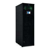
Eaton xStorage Compact User Manual (70 pages)
User interfaces
Brand:
Eaton
| Category:
Recording Equipment
| Size: 22 MB
Table of Contents
Table of Contents
3
Introduction and Use of this Manual
7
Before You Start
7
Technical Disclaimer
7
Legal Entity
7
Conventions Used in this Document
8
Operation Modes
9
Charge
9
Discharge
9
Peak Shave
9
Self-Consumption
10
Figure 1. Example of a Peak Shave Application Triggered by a Global Peak Shave Limit
10
Figure 2. Example of Self-Consumption Optimization Application
11
Control Modes
12
Manual Mode
12
Scheduled Mode
12
Remote Mode
12
Back-Up Energy
13
Global Back-Up Soc
13
Event Back-Up Soc
13
Communication Interfaces
14
Figure 3. Communications Diagram Showing Primary Interface Points between Xstorage and External Devices
14
Application Controller (HMI and Power Management System)
15
Customer Modbus TCP
15
Remote Communication Gateway
15
Monitoring Mode
15
Figure 4. Back View of the Application Controller Showing All Interfaces
15
Access Mode (Eaton Only)
16
Input/Output Contacts
16
Status Leds (Compact Only)
16
Figure 5. Appearance of the LED Lights on the Front Door of Xstorage Compact
16
User Interface (HMI)
17
Figure 6. the HMI, or Application Controller, Is Based on the XV303 Platform and Is Located on the Front Door (for Xstorage Compact)
17
Dashboard: System Overview
18
Figure 7 . the Dashboard with Navigation Bar on the Left, Abstracted System Overview
18
Chart: Graphical Screen
19
Figure 8. Example of Historical Data Displayed in the 'Day' View
20
Figure 9. Weekly View Showing Energy Values (Kwh)
20
Schedule Screen: Programming Operation Modes
21
Figure 10. the Primary View of the Scheduler
21
Figure 11. the Event Selection and Parameter List as Presented in the Table of Events
22
Figure 12. Iinput Page for Event Settings
22
Figure 13. Selection of the Daily Start and Stop Conditions for any Event
23
Figure 14. Default Operation Modes Available in the Application Controller
23
Figure 15. Parameters for Charge / Discharge Operation Modes Are Set Directly in the Bottom Part of the Parameters Window
24
Figure 16. Parameters for Peak Shave / Self-Consumption Operation Modes Are Set on a Dedicated Window
24
Settings Screen
26
Figure 17. Interrupt Schedule Button will Stop the Current Event
26
Figure 18. Settings Menu as Seen by Main User
26
System Settings
27
Figure 19. Control Settings
27
Communication Settings
28
HMI Settings
28
Figure 20. Control Settings
28
System Settings
29
Figure 21. Control Settings
29
Figure 22. Input Options for the Overall System Operation such as Power Limits, Soc Ranges, Ramp Rate, Indicating a PV Power Plant (Second Meter Needed) and System Name
30
Figure 23. Selection of both Grid and PV Meters
31
Figure 24. Single Metering Connection - Picture below Shows an Xstorage Compact
32
Figure 25. Double Metering Connection - Picture below Shows an Xstorage Compact
32
Grid Code Parameters
33
Time and Date
33
Customer Modbus TCP Interface Debugger
33
Figure 26. Grid Code Options
33
Figure 25. GCC Parameters Allowing Grid Code Parameters Customization by Eaton FSE
33
Figure 27. each Element of Date and Time Can be Set
33
Password Management
34
Figure 28. Customer TCP Debugging Page (Accessible after Login)
34
Figure 29. Login Window
35
Figure 30. Choice of User Rights Types
35
Figure 31. Example of Password Setting Panel, as Seen for a Main User
35
Unit Control Screen
36
Figure 32. Change Password Input Panel
36
PCS Details Window
37
Figure 33. the PCS Details Page Provides Data for the Bidirectional Input and Backup Output Side of the PCS
37
Figure 34. Battery Window
38
Figure 35. Battery BMS Values
38
Meter Details Window
39
Figure 36. Power Meters Values with Only Grid Power Meter Connected
39
System Information
40
Figure 37. System Details
40
Display and Error Handling Section
41
Figure 38. an Alarm Button Appears When an Error or Warning Is Detected
41
Figure 39. Figure 39 Latest Alarms View
41
Figure 40. "Show Latest" Alarms View
42
Figure 41. Saved File .Txt File. to Get Back to the Alarms Tab, Reduce the .Txt File Window
42
Multi-Unit System
43
Glossary
43
Topology
43
Figure 42. Schematic Showing the Topology of a System Consisting of 3 Units in Parallel
43
Dashboard: System Overview
44
Figure 43. Schematic Showing the Topology of a System Consisting of 3 in X3 Paralleling Mode
44
Pool Control
45
Figure 44. Dashboard System Overview. Central Portion - no Units Connected
45
Figure 45. Pool Control Page
45
Figure 46. Pool Status Block on the Pool Control Page
46
Figure 47. Pool Status Legend
46
Figure 48. Pool Details
47
Figure 49. Unit Details
48
Figure 50. Top Bar -Switching between Units Details and Pool View
49
Figure 51. Selective Mode Control Switch - no (Off) Position
49
Figure 52. Selective Mode Control Switch - Yes (On) Position
49
X3 Paralleling
50
Figure 53. Manual Mode Control Switch - no (Off) Position - Manual Controls Are Locked
50
Figure 54. Manual Mode Control Switch - Yes (On) Position - Manual Controls Are Unlocked
50
Figure 55. Pool Details
50
Unit Enumeration
52
Figure 56. Unit Enumeration Button Found of Settings Screen
53
Figure 57. Unit Enumeration Confirmation Dialog
53
Errors and Alarms
54
Figure 58. Errors and Alarms Page
54
Remote Interfaces
55
Customer Modbus TCP
55
Pool Management
55
VNC Setup
55
Web-Based Monitoring Platform - Argos Cloud
55
Figure 59. Terminal Layout of Xstorage Compact
55
Figure 60. the Argos Cloud Platform Allows to Monitor Xstorage Data from an Internet Browser
56
Figure 61. Live Values from Xstorage Are Displayed on a Table
57
Figure 62. Historical Data Tab, with the Graph and the Parameters that Can be Displayed
57
API (Optional)
58
Figure 63. Alarm Tab in Argos
58
Figure 64. Alarm Forwarding Tab
58
Commissioning
59
Initial Start-Up and Shut down
59
First Time Start-Up
59
Shutting down a Commissioned System
59
Starting a Commissioned System
59
Operating Instructions and Conditions
60
Maintenance
61
Important Safety Instructions
61
Figure 65. Warning Label
61
Preventative Maintenance
62
Recycling of Used Batteries
63
Figure 66. WEEE Symbol
64
Maintenance Training
65
Troubleshooting and Support
66
Security
66
Cyber Security
66
Password Protection
66
Miscellaneous
67
Warranty and Life Cycle for Battery Packs
67
Appendix
67
Figure 67. Schematic View of Xstorage Internal Components and Links to the Electrical Installation (Example)
67
Figure 68. Communication Flow
68
Figure 69. Eaton XV303 Interfaces (See XV303 User Manual for more Details)
68
Figure 70. Daily Consumption/Production Profile (Without Battery)
69
Advertisement
Eaton xStorage Compact Installation Manual (60 pages)
energy storage system 20 kW - 200 kW
Brand:
Eaton
| Category:
Storage
| Size: 3 MB
Table of Contents
Table of Contents
3
How to Read this Manual
5
Safety-Related Signs
5
Symbols and Abbreviations
5
Conventions Used in this Document
7
Safety Instructions
7
General Safety Instructions
7
Warnings and Cautions Related to Logistics
7
Warnings and Cautions Related to Installation
8
Battery Installation Fire Safety
10
Introduction
10
Introduction to Eaton Xstorage Compact Energy Storage System
10
Electrical System Diagram
10
System Description and Main Components
12
Looking Inside the Eaton Xstorage Compact 20 Kw - 40 Kw
13
Battery System
14
External Battery Rack
16
System Controller and Communication Box
18
Application Controller
19
Site Requirements and Unpacking
19
Location and Cooling Requirements
19
Dimensions
20
Unpack the Xstorage Compact System
21
Mounting and Installation
26
Before You Start
26
Install the Xstorage Compact Unit
26
Install Battery Packs
27
AC and DC Cabling of the Energy Storage System
32
AC and DC Cable Connections
33
AC and DC Cable Cross-Section Requirements
33
Minimum Recommended Fuse Sizes
34
Install a Remote EPO Switch
34
Communication Interface Connections
35
Customer Communication Interface
35
Remote Access for Eaton Technical Support
36
Digital Signal Inputs and Outputs
36
General Alarm Relay Output
36
Internal Communication Connections
36
Battery Breaker Wiring
36
CAN Cabling of Internal Battery Packs
37
Install the External Battery Rack
39
Installation and Cabling of Grounding
44
Earth Cabling Inside the Energy Storage System
45
Earth Cabling Inside the External Battery Rack
48
Wiring Parallel Xstorage Compact Energy Storage Systems
50
Install the Interface Connections
51
First Time System Start-Up
51
Technical Data
52
About Technical Data
52
Eaton Xstorage Compact 20 Kw - 40 Kw Energy Storage System, Technical Specifications
52
Battery Pack, Technical Specifications
56
Appendix A: Example of Xstorage Compact Connected to Tn-C Earthing System
58
Advertisement
Related Products
Eaton xStorage Compact 20 kW
Eaton xStorage 400
Eaton XSTH3P050P075V01
Eaton XSTH3P060P090V01
Eaton XSTH3P080P120V01
Eaton XSTH3P100P150V01
Eaton xStorage Home Series
Eaton xStorage Home
Eaton xStorage XSTHS1P060BP20V1
Eaton xStorage XSTHS1P060BP25V1
Eaton Categories
UPS
Circuit breakers
Switch
Industrial Equipment
Industrial Electrical
More Eaton Manuals
Login
Sign In
OR
Sign in with Facebook
Sign in with Google
Upload manual
Upload from disk
Upload from URL