Sign In
Upload
Manuals
Brands
Eaton Manuals
Controller
MVX9000 Series
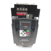
Eaton MVX9000 Series Frequency Drives Manuals
Manuals and User Guides for Eaton MVX9000 Series Frequency Drives. We have
2
Eaton MVX9000 Series Frequency Drives manuals available for free PDF download: User Manual, Quick Start Manual
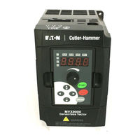
Eaton MVX9000 Series User Manual (180 pages)
AF Drives, Cutler-Hammer
Brand:
Eaton
| Category:
Controller
| Size: 2 MB
Table of Contents
Table of Contents
5
List of Figures
8
Definitions and Symbols
11
Hazardous High Voltage
11
Warnings, Notes and Cautions
12
Chapter 1 - Introduction
17
How to Use this Manual
18
Intended Audience
19
Conventions Used in this Manual
19
Warranty and Liability Information
20
Related Publications
20
Chapter 2 - Overview of the Mvx9000 Drive
21
Receiving and Inspection
22
Nameplate Information
22
Catalog Number
22
Figure 2-1: Example of 1/2 Hp 230V AC Drive
22
Table 2-1: MVX9000 Catalog Numbering System
22
Style Number
23
External Parts and Label Locations
23
Figure 2-2: Parts and Label
23
Digital Keypad Operation
24
Figure 2-3: Description of Digital Keypad
24
Figure 2-4: Explanation of the LED Indicators
24
Table 2-2: Keypad Operators
25
Table 2-3: Explanation of Display Messages
26
Chapter 3 - Storage and Installation
27
Storage
28
Environment
28
Operation
28
Transportation
28
Pollution Degree
28
Mounting Area
29
Figure 3-1: Mounting in an Enclosure in Inches (MM)
29
Wiring
30
Applicable Codes
30
Basic Wiring Diagram
31
Figure 3-2: Circuit Diagram
31
External Wiring
32
Figure 3-3: External Wiring
32
Table 3-1: Wiring Items
32
Control Terminal Wiring (Factory Settings)
33
Figure 3-4: Control Terminal Wiring (Factory Settings)
33
Table 3-2: Terminal Symbols
33
Main Circuit Wiring
34
Figure 3-5: Main Circuit
34
Table 3-3: Wire Gauge and Torque Tightening
34
Wiring Notes
35
Motor Operation Precautions
36
MVX9000 User Manual
36
Figure 3-6: Parallel Grounding
36
Chapter 4 - Start-Up Procedures
37
Step-By-Step Installation
38
Mounting Location
38
Figure 4-1: Clearances and Air Flow in Inches (MM)
39
Inverter Mounting
40
Wiring Preparation
41
Wire Sizes
42
Table 4-1: Wire Size
42
Fuses and Circuit Breakers
43
Fusing
43
Manual Motor Starters/Ul489 Circuit Breakers
43
Table 4-2: Fuse Specification Chart
43
Table 4-3: Heat Loss Data
44
Wiring the Inverter to Incoming Power
45
Wiring the Motor to the Inverter Output
46
Power-Up Test
47
Powering the Inverter
48
Chapter 5 - Descriptions of Parameter Settings
49
Viewing and Changing Parameter Settings
50
Figure 5-2: Parameter Groups
50
Figure 5-3: Parameters
50
Figure 5-4: Programming Mode
51
Figure 5-5: Parameter Changes
51
Parameter Groups
52
Group 20 - Basic Grouping (Quick Start)
53
Group 30 - Inputs
55
Figure 5-6: 0 - 10V Analog Input
57
Figure 5-7: 10 Hz Positive Offset
58
Figure 5-8: 0 - 5V Analog Command Range
59
Figure 5-9: 1V Negative Bias
60
Figure 5-10: Forward and Reverse Programming
61
Figure 5-11: DI1 and DI2 Settings
62
Explanations: Digital Input Terminal
64
Figure 5-14: Digital Input Terminal Settings 05, 06, 07
65
Figure 5-15: Digital Input Terminal Setting 08
66
Figure 5-18: Digital Input Terminal Settings 13, 14
67
Figure 5-21: Digital Input Terminal Setting 17
68
Figure 5-23: Digital Input Terminal Settings 19, 20
69
Figure 5-25: Digital Input Terminal Settings 22, 23
70
Figure 5-27: Digital Input Terminal Setting 25
71
Figure 5-30: Digital Input Terminal Settings 29, 30
72
Group 40 - Outputs
75
Figure 5-33: R01, R02 and R03 Settings
76
Function Explanations
77
Figure 5-34: Desired Freq. Attained & Preset Freq. Attained
78
Group 50 - AC Drive Control
79
Figure 5-35: Stop Methods
79
Figure
81
Figure 5-36: V/F Curve Changes
81
Figure 5-37: Acceleration and Deceleration Times
83
Figure 5-38: S-Curve Effects
84
Figure 5-39: Jog Frequency
85
Figure 5-40: Power Loss Parameters
87
Figure 5-41: Skip Frequency Parameters
88
Figure 5-42: One PLC Program Cycle
91
Figure 5-43: Continuous PLC Program
92
Figure 5-44: Direction of Motion
93
Figure 5-45: Sleep Time Delay
96
Group 60 - Motor Control
98
Figure 5-46: DC Braking
100
Table 5-1: Carrier Frequency
101
Group 70 - Protective Functions
102
Figure 5-47: Over-Voltage Stall Prevention
102
Figure 5-48: Over-Current Stall Prevention
103
Figure 5-49: I2T Curves
105
Figure 5-50: Output Voltage Adjustment
106
Group 80 - Display
107
Table 5-2: Using Decimals
109
Group 90 - Communications
111
Figure 5-51: Communication Address
111
Table 5-3: Communication Mapping Table
113
Computer Control
115
Figure 5-52: Pin Definition
115
Table 5-4: ASCII Characters
115
Data Format
116
Figure 5-53: 10-Bit and 11-Bit Character Frames
116
Table 5-5: Communication Protocol
117
ADR (Communication Address)
118
CMD (Command Code) and DATA (Data Characters)
118
Table 5-6: ASCII Mode
118
Table 5-7: RTU Mode
119
Table 5-8: Example ASCII Mode
120
Table 5-9: Example RTU Mode
120
CHK (Check Sum)
121
Table 5-10: ASCII Mode
121
Table 5-11: RTU Mode
121
Chapter 6 - Maintenance and Inspection
125
Periodic Inspection
126
Periodic Maintenance
126
Chapter 7 - Troubleshooting and Fault Information
127
Common Problems and Solutions
128
Table 7-1: Common Problems and Solutions
128
Warning Codes
131
Table 7-2: Warning Codes
131
Appendix A Technical Data
133
Technical Data
133
Table A-1: MVX9000 115V Specifications
134
Table A-2: MVX9000 230V Specifications
135
Table A-3: MVX9000 460V Specifications
137
Table A-4: MVX9000 575V Specifications
138
Appendix B Parameter Tables
139
MVX9000 Parameter Listing
140
Table B-1: 20 - BASIC GROUPING (Quick Start
140
Table B-2: 30 - INPUTS
141
Table B-3: 40 - OUTPUTS
143
Table B-4: 50 - DRIVE CONTROL
144
Table B-5: 60 - MOTOR CONTROL
148
Table B-6: 70 - PROTECTIVE
149
Table B-7: 80 - KEYPAD/DISPLAY
150
Table B-8: 90 - COMMUNICATION PARAMETERS
152
Appendix C Accessories
155
Table C-1: Fuse Specification
155
Fuse Specification
156
Wiring
157
Table C-2: Wiring Table
157
Braking
158
Table C-3: All Braking Resistors & Braking Units Used in AC Drives
158
EMI Filter Cross-Reference
159
Table C-4: EMI Filter Cross-Reference
159
EMI Filters
159
EMI Filters
160
Figure C-1: EMI Filter (K13-000034-0111
160
Figure C-2: EMI Filter (K13-000034-0112
160
Figure C-3: EMI Filter (K13-000034-0113
161
Figure C-4: EMI Filter (K13-000034-0114
161
Figure C-5: EMI Filter (K13-000034-0115
162
Figure C-6: EMI Filter (K13-000034-0116
162
Figure C-7: EMI Filter (K13-000034-0117)
163
DIN Rail Adapter (P/N: MVXDR
164
Figure C-8: DIN Rail Adapter (MVXDR
164
Remote Kit (P/N: MVXRM
165
Meter Keypad Cable
165
Figure C-9: Remote Kit (MVXRM
165
Extension Input/Output (P/N: MVXEIO
166
Figure C-10: Extension I/O (MVXEIO
166
Table C-5: Terminals
167
Appendix D Dimensions
169
Digital Keypad
170
Figure D-1: Digital Keypad - Approximate Dimensions in Inches (MM
170
Figure D-2: Digital Keypad - Mounting Dimensions in Inches (MM
171
Drives
172
Figure D-3: 1/4 - 3 Hp Drive - Approximate Dimensions in Inches (MM
172
Figure D-4: 3 - 10 Hp Drive - Approximate Dimensions in Inches (MM
173
Appendix E - Declaration of Conformity
175
Low Voltage Directive
176
EC Declaration of Conformity
176
Electromagnetic Compatibility
177
EC Declaration of Conformity
177
Advertisement
Eaton MVX9000 Series Quick Start Manual (19 pages)
AF Drives
Brand:
Eaton
| Category:
DC Drives
| Size: 0 MB
Table of Contents
High Voltage
2
Basic Wiring Diagram
3
Step 2 - Keypad Operation
4
Digital Keypad Operation
4
Step 3 - Parameter Navigation
6
Drive Control
10
Motor Control
13
Communication Parameters
16
Step 5 - Troubleshooting Information
17
Advertisement
Related Products
Eaton MMX11 Series
Eaton MMX12 Series
Eaton MMX32 Series
Eaton MMX34 Series
Eaton MS2-RO-T-9-SWD
Eaton MVXF50A0-1
Eaton MVX002A0-2
Eaton MVX002A0-4
Eaton MVX007A0-4
Eaton MVX010A0-4
Eaton Categories
UPS
Circuit breakers
Switch
Industrial Equipment
Industrial Electrical
More Eaton Manuals
Login
Sign In
OR
Sign in with Facebook
Sign in with Google
Upload manual
Upload from disk
Upload from URL