Sign In
Upload
Manuals
Brands
Eaton Manuals
Electronic dictionary
mMINT
Eaton mMINT Manuals
Manuals and User Guides for Eaton mMINT. We have
2
Eaton mMINT manuals available for free PDF download: Installation And Use Manual, Documentation For Installation And Use
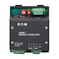
Eaton mMINT Installation And Use Manual (24 pages)
Modbus Translator Module
Brand:
Eaton
| Category:
Control Unit
| Size: 0 MB
Table of Contents
English
1
Table of Contents
1
Section 1: General Description
3
Section 2: Features
3
Section 3: Installation
3
Module Mounting
3
Wiring
3
Figure 1. Mmint in a Communications Network
3
Figure 2. Connections
4
Figure 3. Front View
4
Figure 4. Switches
4
Section 4: Mmint Module Connections
4
Power Connections
4
INCOM Connections
4
Modbus Connections
4
Table 1. Pin J1 Voltage Connector
4
Table 2. INCOM Connector J2 Pins
4
Modbus RS-485 Network Rx LED (Green)
5
Modbus RS-485 Network Tx LED (Green)
5
INCOM Network Rx LED (Green)
5
INCOM Network Tx LED (Green)
5
Status LED (Green)
5
Mmint Diagnostics Address (SW2)
5
Section 5: Switches and Indicator LEDS
4
Section 6: Network Communication Protocols
5
Overview
5
Function Codes
5
Configuring the Data Registers
5
Register Access Configurations
6
Control Commands
6
Data Format for Energy Values
6
Figure 5. Control to INCOM Product Data Format
6
Supported Diagnostic Sub-Functions
7
Exception Codes
7
Figure 6. Four-Register Energy Data Format
7
Table 6. Diagnostic Sub-Function Numbers
7
Table 7. Troubleshooting Guide
7
Section 7: Troubleshooting
7
Table 8. Modbus Register Map (in Register Number Order)
9
Table 9 . Modbus Register Map (in Functional Order)
10
Table 10. Primary Status Code Definitions
11
Table 11. Secondary Status Code Definitions
11
Table 12. Cause of Status Code Definitions
11
Table 13. Control 'Slave Action Number' Definitions
11
Table 14. Mmint Configuration Registers
11
Deutsch
13
Beschreibung Seite
14
Liste der Abbildungen
14
Liste der Tabellen
14
Abschnitt 1: Generelle Beschreibung
15
Abschnitt 2: Funktionen
15
Abschnitt 3: Installation
15
Montage
15
Verdrahtung
15
Abschnitt 4: Mmint Modul-Anschlüsse
16
Stromanschlüsse
16
INCOM Anschlüsse
16
Modbus Anschlüsse
16
Abschnitt 5: Schalter und LED-Anzeigen
16
Tabelle 1. Stecker J1 Spannungsanschluss
16
Tabelle 2. Stecker J2 INCOM Anschluss
16
Tabelle 3. Stecker J3 Modbus RS485-Anschluss
16
Modbus RS485 Netzwerk Rx LED [Grün]
17
Modbus RS485 Netzwerk Tx LED [Grün]
17
INCOM Netzwerk Rx LED [Grün]
17
INCOM Netzwerk Tx LED [Grün]
17
Status-LED [Grün]
17
Modbus RS485 Baudrate(Kippschalter SW2)
17
Mmint Diagnose-Adresse (SW2)
17
Abschnitt 6: Netzwerkkommunikationsprotokolle
17
Übersicht
17
Funktionscodes
17
Konfiguration des Registerzugriffs
18
Steuerbefehle
18
Datenformat für Energiewerte
18
Unterstützte Diagnose-Sub-Funktionen
19
Ausnahmecodes
19
Abschnitt 7: Fehlersuche Und-Behebung
19
Tabelle 6. Diagnose-Sub-Funktionsnummern
19
Tabelle 7. Anleitung zur Fehlersuche
19
Anhang A
20
Tabelle 10. Primäre Statuscode-Definitionen
23
Tabelle 11. Sekundäre Statuscode-Definitionen
23
Tabelle 12. Definitionen der Statusursachencodes
23
Tabelle 13. Steuerung „Slave-Aktions-Nummer" Definitionen
23
Tabelle 14. Mmint Konfigurationsregister
23
Advertisement
Eaton mMINT Documentation For Installation And Use (20 pages)
Modbus translator module
Brand:
Eaton
| Category:
Electronic dictionary
| Size: 1 MB
Table of Contents
Table of Contents
1
List of Figures
2
Figure 1 . the Mmint Module
2
List of Tables
2
Figure 2 . Mmint in a Communications Network
2
Section 1: General Description
2
Section 2: Features
3
Section 3: Installation
3
Module Mounting
3
Simplified Wiring Rules
3
Section 4: Mmint Module Connections
3
Power Connections
3
Figure 3. Connections
3
Table 1. Power Connector Pin Outs
3
INCOM Connections
4
Modbus Connections
4
Section 5: Switches and Indicator Leds
4
Modbus RS-485 Network Rx LED (Green)
4
Modbus RS-485 Network Tx LED (Green)
4
INCOM Network Rx LED (Green)
4
INCOM Network Tx LED (Green)
4
Status LED (Green)
4
INCOM 100 Ohms Termination DIP
4
Switch (SW1)
4
Unique Mmint Address (SW2)
5
Switch (SW3)
5
Section 6: Network Communication Protocols
5
Overview
5
Function Codes
5
Block of Registers
5
Register Access Configurations
5
Table 4. RS-485 Baud Rate Switches (Normal)
5
Table 5. RS-485 Baud Rate Switches (Diagnostics)
5
INCOM Routing Address Configurations
6
Command/Data Pass-Through
6
Control of INCOM Product
6
Figure 6. Pass-Through to INCOM Product Query Data Format
6
Energy Format
7
Figure 7. Pass-Through to INCOM Product Response Data Format
7
Figure 8. Control to INCOM Product Data Format
7
Supported Diagnostic Sub-Functions
8
Exception Codes
8
Figure 9. 4-Register Energy Data Format
8
Table 6. Diagnostic Sub-Function Numbers
8
Table 7. Troubleshooting Guide
9
Section 7: Troubleshooting
9
Table 8. Modbus Register Map (in Register Number Order)
10
Table 9 . Modbus Register Map (in Functional Order)
15
Table 10. Primary Status Code Definitions
17
Table 11. Secondary Status Code Definitions
17
Table 12. Cause-Of-Status Code Definitions
17
Table 13. Control 'Slave Action Number' Definitions
18
Table 14. Mmint Configuration Registers
19
Advertisement
Related Products
Eaton MMX34 Series
Eaton MMX35
Eaton MMX11AA3D7 Series
Eaton MMX12AA7D0 Series
Eaton MMX32AA1D7 Series
Eaton MMX32AA2D8 Series
Eaton MMX34AA1D3 Series
Eaton MMX32AA7D0 Series
Eaton MMX34AA1D9 Series
Eaton MMX34AA9D0 Series
Eaton Categories
UPS
Circuit breakers
Switch
Industrial Equipment
Industrial Electrical
More Eaton Manuals
Login
Sign In
OR
Sign in with Facebook
Sign in with Google
Upload manual
Upload from disk
Upload from URL