Sign In
Upload
Manuals
Brands
Eaton Manuals
Monitor
IQDP4120
Eaton IQDP4120 Manuals
Manuals and User Guides for Eaton IQDP4120. We have
1
Eaton IQDP4120 manual available for free PDF download: Instructions For Installation, Operation And Maintenance
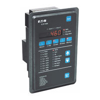
Eaton IQDP4120 Instructions For Installation, Operation And Maintenance (94 pages)
Electrical Distribution System Monitor
Brand:
Eaton
| Category:
Monitor
| Size: 1.7 MB
Table of Contents
Table of Contents
3
1 Introduction
9
Required User-Supplied Hardware
9
Table 1.Amodel Comparison
9
Upgrading from the Iq Data Plus II
10
Replacement Parts
10
Table 1.Bparts and Accessories
10
2 Hardware Description
11
Introduction
11
Operator Panel
11
Rear Access Area
11
Figure 2.1 Three Phase Power Module for Models 4030 and 4130
11
Figure 2.2 Rear Access Area of Chassis
12
User-Supplied External Hardware
13
Optional Communications Module
13
Specifications
13
General Specifications
13
Protective Function Specifications
14
Table 2.Ageneral Specifications
14
Table 2.Bprotection Function (Trip) Specifications
14
Metering Specifications
15
Table 2.Cmetering Specifications
15
3 Operator Panel
16
Introduction
16
Pushbuttons
16
Figure 3.1 Operator Panel
16
Display Window
17
Leds
17
Figure 3.2 Power Quadrants, Mathematical
18
Table 3.Aalarm Codes
19
Figure 3.4 Induction Motor Load
19
Figure 3.5 Power Distribution
19
4 Installation and Startup
20
Introduction
20
Panel Preparation and Mounting the Iq Dp-4000
20
Cutout, Clearances
20
Mounting
20
Figure 4.1 Chassis Cutout Dimensions
20
Mounting the Power Supply Module Separately
21
Wiring
21
Figure 4.2 Side Profile Depth Dimensions
21
Figure 4.3 Power Module Dimensions
21
Figure 4.4 3-Phase, 3-Wire (up to 600 Volts) Wiring Diagram
22
Figure 4.5 3-Phase, 3-Wire (above 600 Volts) Wiring Diagram
23
Figure 4.6 3-Phase, 3-Wire (up to 600 Volts) Wiring Diagram
23
Figure 4.7 3-Phase, 3-Wire (above 600 Volts) Wiring Diagram
24
Figure 4.8 3-Phase, 4-Wire (up to 600 Volts) Wiring Diagram
24
Figure 4.9 3-Phase, 4-Wire (above 600 Volts) Wiring Diagram
25
Figure 4.10 3-Phase, 3-Wire (up to 600 Volts) Wiring Diagram
25
Figure 4.11 3-Phase, 3-Wire (above 600 Volts) Wiring Diagram
26
Figure 4.12 3-Phase, 3-Wire (up to 600 Volts) Wiring Diagram
26
Figure 4.13 3-Phase, 3-Wire (above 600 Volts) Wiring Diagram
27
Figure 4.14 3-Phase, 4-Wire (up to 600 Volts) Wiring Diagram
27
Initial Startup
28
During Initial Power Application
28
Figure 4.15 3-Phase, 4-Wire (above 600 Volts) Wiring Diagram
28
5 Programming the Iq Dp-4000
29
Introduction
29
Table 5.Asetpoint Master Sheet
29
Setting Setpoint Switches
30
Table 5.Bgeneral System Functions
30
Table 5.Calarm Functions
30
Table 5.Doptional I/O Functions
30
Setpoint Switch Programming Example
31
System Configuration Setpoint
31
Frequency Selection Setpoint
31
Nominal Ac Line Voltage Setpoint
31
Table 5.Esetpoint Switch Settings
31
Voltage Transformer Ratio Setpoint
32
Current Transformer Primary Setpoint
32
Phase Sequence Setpoint
32
Demand Setpoints
32
Table 5.Fac Line Voltage
32
Current Demand Time Interval
33
Power Demand Time Interval
33
Power Demand, Fixed/Sliding
33
Energy Setpoints
33
Reset Energy from Faceplate Setpoint
33
Energy Resolution Setpoint
33
Table 5.Gpower Demand Intervals for Watts, Vars and Va
33
Table 5.Hdemand Sampling Interval for Ia, Ib, and IC
33
Var/Power Factor Sign Convention Setpoint
34
Alarm Functions - General
34
Relay Modes Alarm Setpoint
34
Table 5.Ialarm Relay Mode Setting
34
Latched/Unlatched (Auto-Reset) Alarm Setpoint
35
Activate on Overvoltage Alarm Setpoint
35
Activate on Undervoltage Alarm Setpoint
35
Activate on Voltage Phase Loss Alarm Setpoint
35
Activate on Voltage Phase Unbalance Alarm Setpoint
35
Table 5.Jlatched/Unlatched Settings
35
Table 5.Kactivate on Overvoltage Settings
35
Table 5.Lactivate on Undervoltage Settings
35
Table 5.Mactivate on Voltage Phase Loss Settings
35
Table 5.Nactivate on Voltage Phase Unbalance Settings
35
Activate on Voltage Phase Reversal Alarm Setpoint
36
Activate on Current Phase Loss Alarm Setpoint
36
Enable/Disable Alarm Setpoint
36
Alarm Delay Setpoint
36
Alarm Reset Delay Setpoint
36
Table 5.Oactivate on Voltage Phase Reversal Settings
36
Table 5.Pactivate on Current Phase Loss Settings
36
Table 5.Qenable/Disable Alarm Settings
36
Table 5.Ralarm Delay Settings
36
Table 5.Sreset Delay Settings
36
Overvoltage Detection Level Alarm Setpoint
37
Undervoltage Detection Level Alarm Setpoint
37
Voltage Phase Unbalance Detection Level Alarm Setpoint
37
Alarm Reset Threshold Setpoint
37
Table 5.Tovervoltage Detection Level Settings
37
Table 5.Uundervoltage Detection Level Settings
37
Table 5.Vvoltage Phase Unbalance Detection Level Settings
37
Table 5.Wreset Threshold Settings
38
Figure 5.1 Overvoltage Detection and Reset Levels
39
Figure 5.2 Undervoltage Detection and Reset Levels
40
Figure 5.3 Voltage Phase Unbalance Detection/Reset Levels
41
Powernet Programmable Setpoint
42
Dp-4000 / Dp-2 Mode Setpoint
42
Optional I/O Setpoints
42
Discrete Input Setup Setpoint
42
Sync Pulse Setpoint
42
Pulse Initiator/Shed Load Setpoint
42
Table 5.Xpulse Initiator Parameter Selection Settings
43
Table 5.Yload Shed and Restore Load Settings
44
Table 5.Zload Shed Parameter Selection Settings
46
Table 5.Aa Pulse Initiator Rate Selection Settings
46
6 Troubleshooting and Maintenance
47
Level of Repair
47
Maintenance and Care
47
Troubleshooting
47
Replacement
47
Technical Assistance
48
Table 6.Ainitial Power-On Troubleshooting
48
Table 6.Boperational Troubleshooting
49
Return Procedure
50
Advertisement
Advertisement
Related Products
Eaton IQDP4010
Eaton IQDP4020
Eaton IQDP4030
Eaton IQDP4110
Eaton IQDP4130
Eaton Cutler-Hammer IQ DP-4000
Eaton IQ 250
Eaton IQ 260
Eaton Cutler-Hammer IQ320
Eaton Cutler-Hammer IQ330
Eaton Categories
UPS
Circuit breakers
Industrial Equipment
Switch
Industrial Electrical
More Eaton Manuals
Login
Sign In
OR
Sign in with Facebook
Sign in with Google
Upload manual
Upload from disk
Upload from URL