Sign In
Upload
Manuals
Brands
Eaton Manuals
UPS
EX RT EXB 11
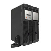
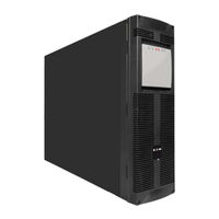
Eaton EX RT EXB 11 Power Supply Manuals
Manuals and User Guides for Eaton EX RT EXB 11 Power Supply. We have
3
Eaton EX RT EXB 11 Power Supply manuals available for free PDF download: Installation And User Manual, Quick Start Manual
Eaton EX RT EXB 11 Installation And User Manual (233 pages)
Brand:
Eaton
| Category:
UPS
| Size: 9 MB
Table of Contents
Environmental Protection
5
Using this Document
5
Table of Contents
6
Presentation
8
Standard Configurations
8
Tower Configuration
8
Rack Configuration
8
Power Module EX RT 7/11
8
Battery Module EX RT EXB 7/11
8
Rear Panels
9
Display and Control Panel
10
Options
10
Rack Mounting Kits
10
Transformer for Galvanic Isolation or Earthing Arrangement Change
11
Battery Extensions for UPS Backup Times up to 60 Minutes
12
CLA Module (Long Backup Time Charger) for Backup Times from 2 to 8 Hours
12
Modules Integration System
13
Battery Module with Remote Emergency Power off Function (REPO)
13
Battery Extension Cable (1,8 M / 6 Ft)
14
Installation
14
Unpacking and Parts Check
14
Power Module
14
Installation in Tower Configuration
15
Installation in Rack Configuration
16
Adjustment of the Orientation of the Logo and Control Panels
16
Battery Module Rack Mounting (Optional Rail Required)
16
Power or Battery Module Rack Mounting (Optional Rail Required)
17
Communication Ports
19
Connection to the RS232 Communication Port
19
Connection to the Communications Port by Relays
19
Remote Power off
20
Remote Power off Communication Port 3
20
Installation of Communication Cards (Optional, Standard with the Network Pack Version)
20
Installation Depending on the System Earthing Arrangement (SEA)
21
UPS with Common Normal and Bypass AC Inputs
21
UPS with Separate Normal and Bypass AC Inputs
21
UPS with Separate Normal and Bypass AC Inputs, Supplied by Separate Sources
22
Frequency Converter (Without Bypass AC Input)
22
Hot Standby
22
Required Protective Devices and Cable Cross-Sections
23
Recommended Upstream Protection
23
Recommended Downstream Protection
23
Required Cable Cross-Section
23
Connections of Input/Output Power Cables
24
UPS with Common Normal and Bypass AC Sources
24
UPS with Separate Normal and Bypass AC Sources
25
Frequency Converter
26
Connection of Battery Cables
27
Connection of Galvanic Isolation Transformer
27
Connection of CLA Module
28
Operation
29
Initial Start up
29
UPS Personalisation
29
Accessing Personalisation with Front Panel Buttons
29
Access to the Personalisation through External Software
30
Final Start up Sequence
30
Operating Modes
31
Normal (Double Conversion) Mode
31
Eco Mode
31
Operation on Battery Power
32
Transfer to Battery Power
32
Threshold for the Low-Battery Warning
32
End of Backup Time
32
Return of Normal AC Source
32
Shut down
33
Maintenance
34
Troubleshooting
34
Hot-Swapping the Power Module
35
Disconnecting the Power Module
35
Tower Configuration
35
Rack Configuration
35
Reconnecting the Power Module
36
Hot-Swapping the Battery Module
36
Disconnecting the Battery Module
36
Reconnecting the Battery Module
36
Training Center
37
Appendices
38
Technical Specifications
38
Electrical Characteristics
38
Thermal Characteristics
40
Glossary
41
Appendices
41
Manuel D'installation et D'utilisation
42
Respect de L'environnement
43
Présentation
46
Positions Standards
46
Position Tour
46
Position Rack
46
Module de Puissance EX RT 7/11
46
Module Batterie EX RT EXB 7/11
46
Faces Arrières
47
Panneau D'affichage et de Commande
48
Options
48
Kits de Montage en Rack
48
Transformateur D'isolement Galvanique ou D'adaptation aux Schémas de Liaison à la Terre
49
Module Batterie Équipé D'arrêt D'urgence (REPO)
51
Câble pour Module Batterie Éloigné (1,8 M)
51
Installation
52
Déballage et Vérification du Contenu
52
Module de Puissance
52
Module Batterie
52
Installation en Position Tour
53
Installation en Position Rack
54
Modification de L'orientation du Logo et du Panneau de Commande
54
Montage en Rack du Module Batterie (Rails Optionnels Requis)
54
Ports de Communication
57
Raccordement du Port de Communication RS232
57
Caractéristiques du Port de Communication Par Relais 2
57
Arrêt D'urgence
58
Raccordement de L'arrêt D'urgence 3
58
Installation des Cartes de Communication (en Option, Standard Dans la Version Network Pack)
58
Choix D'installation Selon le Schéma de Liaison à la Terre (SLT)
59
ASI Avec Réseaux D'entrée AC Normal et AC Bypass Communs
59
ASI Avec Réseaux D'entrée AC Normal et AC Bypass Séparés
59
Redondance Secours
60
Sections de Câbles Recommandées
61
Raccordement des Câbles de Puissance D'entrée et Sortie
62
Raccordement D'une ASI Avec Réseaux D'entrée AC Normal et AC Bypass Communs
62
Raccordement D'une ASI Avec Réseaux D'entrée AC Normal et AC Bypass Séparés
63
Raccordement du Convertisseur de Fréquence
64
Raccordement des Câbles Batterie
65
Raccordement du Transformateur D'isolement Galvanique
65
Raccordement du Module Chargeur Longue Autonomie (CLA)
66
Utilisation
67
Mise en Service Initiale
67
Personnalisation de L'asi
67
Personnalisation Par le Panneau de Commande
67
Personnalisation Par Logiciel Externe
68
Séquence de Démarrage de L'asi
68
Modes de Fonctionnement
69
Mode Normal (Double Conversion)
69
Mode Eco
69
Fonctionnement Sur Batterie
70
Passage Sur Batterie
70
Seuil de Préalarme de Fin D'autonomie
70
Fin D'autonomie Batterie
70
Retour du Réseau AC Normal
70
Arrêt de L'asi
71
Maintenance
72
Anomalies
72
Remplacement du Module de Puissance
73
Déconnexion du Module de Puissance
73
Reconnexion du Module de Puissance
74
Remplacement du Module Batterie
74
Déconnexion du Module Batterie
74
Reconnexion du Module Batterie
74
Centre de Formation
75
Annexes
76
Spécifications Techniques
76
Caractéristiques Électriques
76
Caractéristiques Thermiques
78
Glossaire
79
Index
79
Installations- und Bedienungsanleitung
80
Ansichten und Beschreibung
84
Aufstellungsarten
84
Tower-Modell
84
Rack-Modell
84
Batteriemodul EX RT EXB 7/11
84
Anzeige- und Bedienfeld
86
Optionen
86
Montagematerial für Rackeinbau
86
Trenn- und Anpaßtransformator für Unterschiedliche Netzformen
87
CLA-Modul (Hochleistungsladegerät) für Autonomiezeiten von 2 bis 8 Stunden
88
Fahrbares Rahmengestell für Einbau Mehrerer Module
89
Batteriemodul mit Not-AUS-Funktion (REPO)
89
Aufstellung und Installation
90
Entfernen der Verpackung und Überprüfung des Lieferumfangs
90
USV-Modul
90
Batteriemodul
90
Aufstellung des Tower-Modells
91
Einbau des Rack-Modells
92
Einbau des Batteriemoduls (Optionale Montageschienen Erforderlich)
92
Kommunikationsanschlüsse
95
Anschluß an RS232-Schnittstelle
95
Kontaktbelegung der Relais-Schnittstelle 2
95
Not-AUS-Vorrichtung
96
Anschluß der Not-AUS-Verbindung 3
96
Einbau der Kommunikationskarten
96
Installation in Abhängigkeit von der Netzform (Erdungssystem)
97
USV mit Gemeinsamer Einspeisung von Netz 1 (Gleichrichter) und Netz 2 (Bypass)
97
USV mit Getrennter Einspeisung von Netz 1 (Gleichrichter) und Netz 2 (Bypass) aus Unterschiedlichen Netzen
98
Frequenzwandler (ohne NRE-Zweig)
98
Standby-Redundanz
98
Empfohlene Schutzorgane und Leiterquerschnitte
99
Netzseitige Absicherung
99
Absicherung am USV-Ausgang
99
Leiterquerschnitte
99
Anschluß der Leistungskabel am USV-Eingang und -Ausgang
100
Anschluß einer USV mit Gemeinsamer Einspeisung von Netz 1 (Gleichrichter)
100
Anschluß einer USV mit Getrennter Einspeisung von Netz 1 (Gleichrichter)
101
Anschluß des Frequenzwandlers
102
Anschluß der Batteriekabel
103
Betriebszustände
105
Erstinbetriebnahme
105
Kundenspezifische Anpassung der USV
105
Anpassung über das Bedien- und Anzeigefeld
105
Anpassung über Software
106
Einschalten der USV
106
Betriebsarten
107
Normalbetrieb (Doppelwandlerprinzip)
107
ECO-Mode
107
Batteriebetrieb
108
Umschaltung auf Batteriebetrieb
108
Voralarm "Ende der Autonomiezeit
108
Abschaltung am Ende der Autonomiezeit
108
Rückkehr von Netz 1 (AC Normal)
108
Abschaltung der USV
109
Wartung und Service
110
Betriebsstörungen
110
Austausch des USV-Moduls
111
Abschaltung und Lösen der Verbindungen
111
Tower-Modell
111
Wiederanschluß des USV-Moduls
112
Austausch des Batteriemoduls
112
Abschaltung und Lösen der Verbindungen
112
Wiederanschluß des Batteriemoduls
112
Schulungszentrum
113
Anhang
114
Technische Kenndaten
114
Elektrische Kenndaten
114
Thermische Kenndaten
116
Fachbegriffe
117
Stichwortregister
117
Rispetto Dell'ambiente
119
Presentazione
122
Posizioni Standard
122
Posizione "Tower
122
Posizione "Slot
122
Parti Posteriori
123
Modulo DI Potenza EX RT 7/11
123
Modulo Batteria EX RT EXB 7/11
123
Pannello DI Visualizzazione E DI Controllo
124
Opzioni
124
Kit DI Montaggio in Posizione Slot
124
Modulo Batteria Munito DI Arresto DI Emergenza (REPO)
127
Cavo Per Modulo Batteria Distanziato (1,8 M)
127
Installazione
128
Apertura Dell'imballaggio E Verifica del Contenuto
128
Modulo DI Potenza
128
Modulo Batteria
128
Installazione Nella Posizione "Tower
129
Installazione Nella Posizione "Slot
130
Modifica Dell'orientamento del Logo E del Pannello DI Controllo
130
Montaggio in Slot del Modulo Batteria (Guide Opzionali Richieste)
130
Porte DI Comunicazione
133
Collegamento Della Porta DI Comunicazione RS232
133
Caratteristiche Della Porta DI Comunicazione a Relè 2
133
Arresto DI Emergenza
134
Collegamento Dell'arresto DI Emergenza 3
134
Installazione Delle Schede DI Comunicazione
134
Scelta DI Installazione Secondo lo Schema DI Collegamento Alla Terra (SCT)
135
UPS con Reti DI Ingresso CA Normale E CA By-Pass Comuni
135
UPS con Reti DI Ingresso CA Normale E CA By-Pass Separate
135
Ridondanza DI Emergenza
136
Organi DI Protezione E Sezioni DI Cavi Raccomandati
137
Protezione a Monte Raccomandata
137
Protezione a Valle Raccomandata
137
Sezioni DI Cavi Raccomandate
137
Collegamento Dei Cavi DI Potenza DI Ingresso E Uscita
138
Collegamento DI un UPS con Reti DI Ingresso CA Normale E CA By-Pass Comuni
138
Collegamento DI un UPS con Reti DI Ingresso CA Normale E CA By-Pass Separate
139
Collegamento del Convertitore DI Frequenza
140
Collegamento Dei Cavi Batteria
141
Collegamento del Trasformatore DI Isolamento Galvanico
141
Collegamento del Modulo Caricatore a Lunga Autonomia (CLA)
142
Personalizzazione Dell'ups
143
Personalizzazione Tramite Il Pannello DI Controllo
143
Personalizzazione Tramite Software Esterno
144
Sequenza DI Avviamento Dell'ups
144
Modalità DI Funzionamento
145
Modalità Normale (Conversione Doppia)
145
Modalità Eco
145
Funzionamento a Batteria
146
Passaggio Sulla Batteria
146
Fine Autonomia Della Batteria
146
Ripristino Della Rete CA Normale
146
Arresto Dell'ups
147
Risoluzione Avarie
148
Sostituzione del Modulo DI Potenza
149
Scollegamento del Modulo DI Potenza
149
Ricollegamento del Modulo DI Potenza
150
Sostituzione del Modulo Batteria
150
Scollegamento del Modulo Batteria
150
Ricollegamento del Modulo Batteria
150
Centro DI Formazione
151
Allegati
152
Specifiche Tecniche
152
Caratteristiche Elettriche
152
Caratteristiche Termiche
154
Glossario
155
Indice Analitico
155
Respeto del Medio Ambiente
157
Presentación
160
Posiciones Estándares
160
Posición Rack
160
Caras Traseras
161
Módulo de Potencia EX RT 7/11
161
Módulo de Batería EX RT EXB 7/11
161
Tablero de Visualización y de Mando
162
Opciones
162
Kits de Montaje en Rack
162
Transformador de Aislamiento Galvánico O de Adaptación para Esquemas de Enlace a Tierra
163
Extensiones de Batería para Autonomías de la Batería de 60 Minutos Máximo
164
Módulo de Batería Equipado con Parada de Emergencia (REPO)
165
Instalación
166
Desembalaje y Comprobación del Contenido
166
Módulo de Potencia
166
Módulo de Batería
166
Instalación en Posición Torre
167
Instalación en Posición Rack
168
Modificación de la Orientación del Logotipo y del Tablero de Mando
168
Montaje en Rack de Los Módulos Batería y Potencia
169
Puertos de Comunicación
171
Conexión del Puerto de Comunicación RS232
171
Características del Puerto de Comunicación por Relé 2
171
Paro de Emergencia
172
Conexión de la Parada de Emergencia 3
172
Instalación de las Tarjetas de Comunicación (Opcional, Estándar en la Versión Network Pack)
172
Selección de la Instalación Según el Esquema de Enlace a Tierra (EET)
173
SAI con Redes de Entrada AC Normal y AC Bypass Comunes
173
SAI con Redes de Entrada AC Normal y AC Bypass Separadas
173
SAI con Redes de Entrada AC Normal y AC Bypass Separadas y Procedentes de Diferentes Fuentes
174
Convertidor de Frecuencia (sin Red de Entrada AC Bypass)
174
Organos de Protección y Secciones de Cables Recomendados
175
Protección Aguas Arriba Recomendada
175
Protección Aguas Abajo Recomendada
175
Conexión de Los Cables de Potencia de Entrada y Salida
176
Conexión de un SAI con Redes de Entrada AC Normal y AC Bypass Comunes
176
Conexión de un SAI con Redes de Entrada AC Normal y AC Bypass Separadas
177
Conexión del Convertidor de Frecuencia
178
Conexión de Los Cables de la Batería
179
Conexión del Transformador de Aislamiento Galvánico
179
Conexión del Módulo Cargador de Larga Autonomía (CLA)
180
Utilización
181
Puesta en Servicio Inicial
181
Personalización del SAI
181
Personalización Mediante el Tablero de Mando
181
Personalización Mediante Software Exterior
182
Secuencia de Inicio del SAI
182
Modos de Funcionamiento
183
Modo Normal (Doble Conversión)
183
Modo Eco
183
Funcionamiento con Batería
184
Cambio a Batería
184
Fin de Autonomía de la Batería
184
Retorno de la Red AC Normal
184
Parada del SAI
185
Mantenimiento
186
Anomalías
186
Reemplazo del Módulo de Potencia
187
Desconexión del Módulo de Potencia
187
Conexión del Módulo de Potencia
188
Reemplazo del Módulo de Batería
188
Desconexión del Módulo de Batería
188
Conexión del Módulo de Batería
188
Centro de Formación
189
Anexos
190
Características Eléctricas
190
Características Térmicas
192
Glosario
193
Indice
193
Gebruik Van Deze Handleiding
195
Beschrijving
198
Rack-Opstelling
198
Achterpanelen
199
Power Module EX RT 7/11
199
Batterijmodule EX RT EXB 7/11
199
Display en Instrumentenpaneel
200
Opties
200
Sets Voor Rackmontage
200
Transformator Voor Galvanische Isolatie of Aanpassing Aan Aardingsschema's
201
Batterijmodule Met Noodstop (REPO)
203
Kabel Voor Batterijmodule Op Afstand (1,8 M)
203
Installeren
204
Uitpakken en Inhoud Controleren
204
Power Module
204
Batterijmodule
204
Tower-Opstelling
205
Rack-Opstelling
206
Horizontaal of Verticaal Plaatsen Van Logo en Instrumentenpaneel
206
Rackmontage Van Batterijmodule (Optionele Rails Vereist)
206
Aansluiten Van de RS232-COM-Poort
209
Specificaties Van de COM-Poort Met Relais 2
209
Noodstop
210
Aansluiten Van de Noodstop 3
210
Installeren Van de Communicatiekaarten (Optioneel; Standaard Bij Network Pack Uitvoering)
210
Installatieopties Afhankelijk Van Aardingsschema (SLT)
211
UPS Met Gemeenschappelijke Ingangen Voor Normale AC- en AC-Bypass-Circuit
211
UPS Met Gescheiden Ingangen Voor Normale AC- en AC-Bypass-Circuit
211
Aanbevolen Beveiligingsorganen en Kabeldiameters
213
Aanbevolen Stroomopwaartse Beveiliging
213
Aanbevolen Stroomafwaartse Beveiliging
213
Aanbevolen Kabeldiameters
213
Aansluiten Van Ingangs- en Uitgangsvermogenskabels
214
AC-Bypass-Circuit
216
Aansluiten Van de Frequentieomzetter
216
Aansluiten Van de Batterijkabels
217
Aansluiten Van de Galvanische Isolatietransformator
217
Aansluiten Van de Lange Autonomie Lader (CLA-Module)
218
Gebruik
219
Eerste Ingebruikname
219
Specifieke Programmering Van de UPS
219
Specifieke Programmering Via Het Instrumentenpaneel
219
Specifieke Programmering Via Externe Software
220
Tartprocedure Van de UPS
220
Bedrijfsmodes
221
Eco-Mode
221
Werking Op Batterij
222
Overschakelen Op Batterij
222
Vooralarmgrens Einde Autonomie
222
Einde Autonomie Batterij
222
Uitschakelen Van de UPS
223
Onderhoud
224
Storingen
224
Vervangen Van de Power Module
225
Loskoppelen Van de Power Module
225
Opnieuw Aansluiten Van de Power Module
226
Vervangen Van de Batterijmodule
226
Loskoppelen Van de Batterijmodule
226
Opnieuw Aansluiten Van de Batterijmodule
226
Opleidingscentra
227
Bijlagen
228
Technische Specificaties
228
Elektrische Speceficaties
228
Thermische Speceficaties
230
Woordenlijst
231
Index
231
Advertisement
Eaton EX RT EXB 11 Installation And User Manual (38 pages)
Brand:
Eaton
| Category:
UPS
| Size: 2 MB
Table of Contents
Environmental Protection
2
Table of Contents
3
1 Presentation
5
Standard Configurations
5
Tower Configuration
5
Rack Configuration
5
Rear Panels
6
Power Module EX RT 5/7/11
6
Battery Module EX RT EXB 7/11
6
Display and Control Panel
7
Options
7
Rack Mounting Kits
7
Transformer for Galvanic Isolation or Earthing Arrangement Change
8
Battery Extensions for UPS Backup Times up to 60 Minutes
9
CLA Module (Long Backup Time Charger) for Backup Times from 2 to 8 Hours
9
Modules Integration System
10
Battery Module with Remote Emergency Power off Function (REPO)
10
Battery Extension Cable (1,8 M / 6 Ft)
10
2 Installation
11
Unpacking and Parts Check
11
Power Module
11
Battery Module
11
Installation in Tower Configuration
12
Installation in Rack Configuration
13
Adjustment of the Orientation of the Logo and Control Panels
13
Battery Module Rack Mounting (Optional Rail Required)
13
Power or Battery Module Rack Mounting (Optional Rail Required)
14
Communication Ports
16
Connection to the RS232 Communication Port
16
Connection to the Communications Port by Relays
16
Remote Power off
17
Remote Power off Communication Port 3
17
Installation of Communication Cards (Optional, Standard with the Network Pack Version)
17
Installation Depending on the System Earthing Arrangement (SEA)
18
UPS with Common Normal and Bypass AC Inputs
18
UPS with Separate Normal and Bypass AC Inputs
18
UPS with Separate Normal and Bypass AC Inputs, Supplied by Separate Sources
19
Frequency Converter (Without Bypass AC Input)
19
Hot Standby
19
Required Protective Devices and Cable Cross-Sections
20
Recommended Upstream Protection
20
Recommended Downstream Protection
20
Required Cable Cross-Section
20
Connections of Input/Output Power Cables
21
UPS with Common Normal and Bypass AC Sources
21
UPS with Separate Normal and Bypass AC Sources
22
Frequency Converter
23
Connection of Battery Cables
24
Connection of Galvanic Isolation Transformer
24
Connection of CLA Module
25
3 Operation
26
Initial Start up
26
UPS Personalisation
26
Accessing Personalisation with Front Panel Buttons
26
Access to the Personalisation through External Software
27
Final Start up Sequence
27
Operating Modes
28
Normal (Double Conversion) Mode
28
Eco Mode
28
Operation on Battery Power
29
Transfer to Battery Power
29
Threshold for the Low-Battery Warning
29
End of Backup Time
29
Return of Normal AC Source
29
Shut down
30
4 Maintenance
31
Troubleshooting
31
Hot-Swapping the Power Module
32
Disconnecting the Power Module
32
Reconnecting the Power Module
33
Hot-Swapping the Battery Module
33
Disconnecting the Battery Module
33
Reconnecting the Battery Module
33
Training Center
34
5 Appendices
35
Technical Specifications
35
Electrical Characteristics
35
Thermal Characteristics
38
Glossary
38
Eaton EX RT EXB 11 Quick Start Manual (9 pages)
Battery Module
Brand:
Eaton
| Category:
Camera Accessories
| Size: 0 MB
Table of Contents
Battery Module
2
Quick Start
2
Standard Features
2
STEP 3 Rack Configuration
6
Step 4 System Connections
7
Advertisement
Advertisement
Related Products
Eaton EX EXB 1500RT 2U
Eaton EX EXB 1500
Eaton EX EXB 1000
Eaton Evolution S EXB 1250/1750 RT 2U
Eaton Pulsar EX EXB 1000 RT 2U
Eaton Pulsar EX EXB 1500 RT 2U
Eaton Evolution S EXB 1250 RT 2U
Eaton Evolution S EXB 1750 RT 2U
Eaton EXB 1500
Eaton EXB RT
Eaton Categories
UPS
Circuit breakers
Switch
Industrial Equipment
Industrial Electrical
More Eaton Manuals
Login
Sign In
OR
Sign in with Facebook
Sign in with Google
Upload manual
Upload from disk
Upload from URL