Sign In
Upload
Manuals
Brands
Dynapac Manuals
Construction Equipment
F2500CS
Dynapac F2500CS Manuals
Manuals and User Guides for Dynapac F2500CS. We have
1
Dynapac F2500CS manual available for free PDF download: Operation & Maintenance Manual
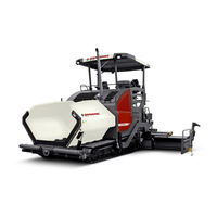
Dynapac F2500CS Operation & Maintenance Manual (410 pages)
Paver Finisher Typ 890 / 891
Brand:
Dynapac
| Category:
Construction Equipment
| Size: 17 MB
Table of Contents
Table of Contents
3
Preface
13
General Safety Instructions
14
Laws, Guidelines, Accident Prevention Regulations
14
Safety Signs, Signal Words
15
Danger
15
Warning
15
Caution
15
Note
15
Other Supplementary Information
15
Warnings
16
Prohibitive Symbols
18
Protective Equipment
19
Environmental Protection
20
Fire Prevention
20
Additional Information
21
CE Identification and Declaration of Conformity
22
Guarantee Conditions
22
Residual Risks
23
Sensibly Predictable Incorrect Usage
24
A Correct Use and Application
25
B Vehicle Description
27
Application
27
Description of Assemblies and Functions
28
Vehicle
29
Construction
29
Danger Zones
33
Safety Devices
34
Technical Data, Standard Configuration
36
Dimensions (All Dimensions in MM)
36
Allowed Angle of Rise and Slope
37
Permissible Approach Angle
37
Weights F2500C (All Weights in T)
38
Weights F2500CS (All Weights in T)
38
Performance Data F2500C
39
Performance Data F2500CS
40
Travel Drive/Traction Unit
41
Engine F2500C
41
Engine F2500CS
41
Hydraulic System
41
Material Compartment (Hopper)
42
Material Transfer
42
Material Distribution
42
Screed Lifting Device
43
Electrical System
43
Permissible Temperature Ranges
43
Location of Instruction Labels and Identification Plates
44
Warning Signs
47
Information Signs
50
CE Marking
52
Instructive Symbols, Prohibitive Symbols, Warning Symbols
53
Danger Symbols
54
Further Warnings and Operating Instructions
55
Identification Label for the Paver Finisher (41)
57
Explanation of 17PIN Serial Number
58
Engine Type Plate
59
Standards
60
Continuous Sound Pressure F2500C, Cummins QSB 6.7-C173
60
Operating Conditions During Measurement
60
Measuring Point Configuration
60
Continuous Sound Pressure F2500CS, Cummins QSB 6.7-C173
61
Operating Conditions During Measurement
61
Measuring Point Configuration
61
Vibration Acting on the Entire Body
62
Vibrations Acting on Hands and Arms
62
Electromagnetic Compatibility (EMC)
62
C10 Transportation
63
Safety Regulations for Transportation
63
Transportation on Low-Bed Trailers
64
Preparations
64
Securing the Load
66
Prepare the Low-Bed Trailer
66
Driving Onto the Low-Bed Trailer
67
Lashing Equipment
68
Loading
69
Preparing the Vehicle
70
Securing the Load
71
Securing at the Sides
71
Securing at the Front
71
Securing at the Rear - Screed with Side Board
72
Securing at the Rear - Screed Without Side Board
73
Step 1: Fasten Lashing Straps
73
Step 2: Fasten Lashing Chains
73
After Transportation
74
Protective Roof (O)
75
Transportation
77
Preparations
77
Driving Mode
79
Loading by Crane
80
Towing
83
Safely Parking the Vehicle
86
Lifting the Vehicle with Hydraulic Lifts, Lifting Points
87
D10 Operation
89
Safety Regulations
89
Controls
91
Operating Panel
91
Truck-Assist-System (O)
122
Remote Control
128
D30 Operation
133
Operating Elements on the Paver Finisher
133
Control Elements on the Operator's Control Station
133
Protective Roof (O)
134
Ladder
136
Storage Space
136
Control Platform, Moveable (O)
137
Control Platform Lock (O)
138
Operating Panel
139
Protective Cabin (O)
140
Windscreen Wiper
141
Emergency Actuation Control Platform, Movable
142
Seat Console
143
Driver's Seat, Type I
144
Fuse Box
146
Batteries
147
Main Battery Switch
147
Hopper Transport Safeguard
148
Screed Lock, Mechanical (O)
148
Screed Lock, Hydraulic (O)
149
Paving Thickness Indicator
150
Auger Lighting (O)
151
Engine Compartment Lighting (O)
151
LED Working Light (O)
152
Watt Spotlight (O)
153
Camera (O)
153
Auger Height Adjustment Ratchet (O)
154
Auger Height Indicators
154
Sensor Rod / Sensor Rod Extension
155
Manual Separator Fluid Spray (O)
157
Separator Fluid Spraying System (O)
158
Conveyor Limit Switches - PLC Version
159
Conveyor Limit Switches - Conventional Version
160
Ultrasonic Auger Limit Switches (Left and Right) - PLC Version
161
Ultrasonic Auger Limit Switches (Left and Right) - Conventional Version
162
Volt / 12 Volt Sockets (O)
163
Pressure Control Valve for Screed Charging/Relieving
164
Pressure Control Valve for Paving Stop with Relieving
164
Manometer for Screed Charging/Relieving
164
Central Lubrication System (O)
165
Lane Clearer (O)
166
Screed Eccentric Adjustment
167
Push Roller Crossbar, Adjustable
168
Push Roller Crossbar, Hydraulically Extendable (O)
169
Push Roller Damping, Hydraulic (O)
169
Fire Extinguisher (O)
170
First-Aid Kit (O)
170
Rotary Beacon (O)
171
Fuelling Pump (O)
172
Illuminated Balloon (O)
173
Installation and Operation
174
Maintenance
175
Replacing the Lamp
175
Truck Assist (O)
176
D40 Mode of Operation
177
Preparing for Operation
177
Required Devices and Aids
177
Before Starting Work (in the Morning or When Starting Paving)
179
Check List for the Machine Operator
179
Starting the Paver Finisher
182
Before Starting the Paver Finisher
182
Normal" Starting
182
External Starting (Starting Aid)
184
After Starting
187
Observe Indicator Lamps
189
Engine Coolant Temperature Check (1)
189
Battery Charge Indicator (2)
189
Oil Pressure Indicator Lamp for the Diesel Engine (3)
189
Preparation for Transportation
191
Driving and Stopping the Paver Finisher
193
Preparations for Paving
194
Separator Fluid
194
Screed Heater System
194
Loading/Conveying Material
197
Starting for Paving
199
Checks During Paving
200
Paver Function
200
Quality of the Layer
200
Paving with "Screed Control at Paver Finisher Stop
201
And "Screed Charging/Relieving
201
General
201
Screed Charging/Relieving
203
Screed Control with Paver Finisher Stop / in Paving Operation (Screed Stop / Floating Stop / Floating Paving)
203
Screed Control with Paver Finisher Stop - Floating Stop with Relief
205
Adjusting the Pressure
205
Set Pressure for Screed Charging or Relieving
205
Setting Pressure for Screed Control with Paver Finisher Stop - Floating Stop with Relief
207
Interrupting/Terminating Operation
209
During Breaks in Paving (E.g. Delay Due to Material Trucks)
209
During Extended Interruptions (E.g. Lunch Break)
209
When Work Is Finished
211
Malfunctions
212
Error Code Query for Engine
212
Output of Numerical Code
214
Error Codes
216
Problems During Paving
223
Malfunctions on the Paver Finisher or Screed
225
E10 Set-Up and Modification
229
Special Notes on Safety
229
Distribution Auger
230
Height Adjustment
230
Grain Sizes up to 16 MM
230
Grain Sizes > 16 MM
230
Mechanical Adjustment with Ratchet (O)
231
Hydraulic Adjustment (O)
231
Height Adjustment for Large Working Widths / with Brace
232
Auger Extension
234
Mounting Extension Parts
235
Mounting the Material Shaft and Auger Extension
235
Mounting the Outer Auger Bearing
236
Mounting the Auger End Bearing
237
Auger Extension Chart
238
Auger Upgrading, Working Width 3.14 M
240
Auger Upgrading, Working Width 3.78 M
240
Auger Upgrading, Working Width 4.42 M
240
Auger Upgrading, Working Width 5.06 M
241
Auger Upgrading, Working Width 5.70 M
241
Auger Upgrading, Working Width 6.34 M
242
Auger Upgrading, Working Width 6.98 M
243
Auger Upgrading, Working Width 7.62 M
244
Auger Upgrading, Working Width 8.26 M
245
Auger Upgrading, Working Width 8.90 M
246
Mounting the Auger Brace
247
Aligning the Auger
249
Material Shaft, Hinged
250
Hopper Scraper
251
Crossbeam Guide
252
Offsetting the Screed
253
Levelling
254
Slope Controller
254
Mounting the Sensor Arm
255
Mounting the Grade Control System
255
Setting up the Sensor Arm
256
Big Ski 9 M, Big Ski 13 M
257
Mounting the Big Ski Bracket on the Crossbeam
259
Mounting the Swivel Arms
260
Mounting the Centre Element
261
Extending the Big Ski
262
Mounting the Sensor Bracket
263
Mounting and Aligning the Sensors
264
Mounting the Distributor Box
265
Connection Diagram
266
Levelling Shoe 6M, 9M
267
Automatic Steering Unit
269
Mounting the Automatic Steering Unit on the Paver Finisher
270
Mounting and Aligning the Sensor
271
Connecting the Sensor
271
Automatic Steering Unit Operating Instructions
272
Emergency Stop During Feeder Operation
273
Limit Switch
274
Auger Limit Switches (Left and Right) - Mounting the PLC Version
274
Auger Limit Switches (Left and Right) - Mounting the Conventional Version
275
Special Accessories
276
Material Bucket
276
Application
276
Description of Assemblies and Functions
277
Technical Data
278
Dimensions, Bucket MH2500 - (Short Version)
278
Dimensions, Bucket MH2550 - (Long Version)
279
Weights
280
Volume
280
Identification Points
281
Information Signs
282
Warning Signs
282
Further Warnings and Operating Instructions
282
Instructive Symbols, Prohibitive Symbols, Warning Symbols
283
Load Securing - Bucket
284
Prepare the Low Loader
284
Lashing Equipment
285
Lashing
286
Loading with the Crane - MH2500
288
Loading with the Crane - MH2550
289
Lash the Bucket in the Paver
291
Operation
293
Operation with a Feeder with Slewing Belt
294
Preparations for Paving
294
Separator Fluid
294
Cleaning the Bucket
295
Screed
296
Electrical Connections
296
Machine Operation Without Remote Control / Side Board
297
F10 Maintenance
299
Notes Regarding Safety
299
F20 Maintenance Review
301
Maintenance Review
301
F30 Maintenance - Conveyor
303
Maintenance - Conveyor
303
Maintenance Intervals
305
Points of Maintenance
306
Chain Tension, Conveyor (1)
306
Conveyor Drive - Drive Chains (2)
308
Conveyor Deflectors / Conveyor Plates (3)
309
F40 Maintenance - Auger Assembly
311
Maintenance - Auger Assembly
311
Maintenance Intervals
313
Points of Maintenance
315
Outer Auger Bearing (1)
315
Auger Planetary Gear (2)
316
Drive Chains of the Augers (3)
317
Auger Box (4)
318
Seals and Sealing Rings (5)
319
Gearbox Bolts Check Tightening (6)
320
Mounting Screws - Outer Auger Bearing Check Tightening (7)
321
Auger Blade (8)
322
F50 Maintenance - Engine Assembly Tier 3 (O)
323
Maintenance - Engine Assembly
323
Maintenance Intervals
325
Points of Maintenance
328
Engine Fuel Tank (1)
328
Engine Lube Oil System (2)
329
Engine Fuel System (3)
332
Engine Air Filter (4)
334
Engine Cooling System (5)
336
Engine Drive Belt (6)
338
F60 Maintenance - Hydraulic System
339
Maintenance - Hydraulic System
339
Maintenance Intervals
341
Points of Maintenance
343
Hydraulic Oil Tank (1)
343
Suction/Return Flow Hydraulic Filter (2)
345
Bleeding the Filter
346
Ventilation Filter
346
High-Pressure Filter (3)
347
Pump Distribution Gear (4)
348
Bleeder
349
Hydraulic Hoses (5)
350
Marking Hydraulic Hoses / Storage Period, Period of Use
352
Auxiliary Flow Filter (6)
353
F73 Maintenance - Drive Units
355
Maintenance - Drive Units
355
Maintenance Intervals
357
Chain Tension (1)
357
Bottom Plates (2)
357
Rollers (3)
357
Planetary Gear (4)
358
Screw Connections
358
F80 Maintenance - Electrical System
369
Maintenance - Electrical System
369
Maintenance Intervals
371
Points of Maintenance
372
Batteries (1)
372
Recharging the Batteries
373
Alternator (2)
374
Insulation Faults
375
Cleaning the Generator
376
Electrical Fuses / Relays (2)
377
Fuses in Terminal Box (B)
378
Relays in Terminal Box (C)
380
Relays in Operating Panel (D)
382
Relays in the Engine Compartment (E)
383
F90 Maintenance - Lubricating Points
385
Maintenance - Lubricating Points
385
Maintenance Intervals
386
Points of Maintenance
387
Central Lubrication System (1)
387
Bearing Points (2)
391
F100 Tests, Stopping
393
Tests, Checks, Cleaning, Stopping
393
Maintenance Intervals
394
General Visual Inspection
395
Check that the Bolts and Nuts Fit Firmly
395
Inspection by an Expert
395
Cleaning
396
Cleaning the Hopper
397
Cleaning the Conveyor and Auger
397
Cleaning Optical or Acoustic Sensors
398
Preserving the Paver Finisher
399
Shutdowns for up to 6 Months
399
Shutdowns Lasting from 6 Months to 1 Year
399
Recommissioning the Machine
399
Environmental Protection, Disposal
400
Environmental Protection
400
Disposal
400
Bolts - Torques
401
Fine Metric Threads - Strength Class 8.8 / 10.9 / 12.9
402
Lubricants and Operating Substances
403
Capacities
405
Lubricant Specifications
406
Engine
406
Cooling System
406
Hydraulic System
406
Pump Distribution Gear
406
Drive Unit Planetary Gear
407
Auger Drive Planetary Gear
407
Auger Box
407
Grease
407
Hydraulic Oil
408
Advertisement
Advertisement
Related Products
Dynapac F2500C
Dynapac F6C
Dynapac F1800W
Dynapac Hatz F80W
Dynapac F1000W T4f
Dynapac F 121 C
Dynapac F 141 C
Dynapac F1800C
Dynapac F1250CS
Dynapac F1200CS
Dynapac Categories
Construction Equipment
Power Tool
Finishers
Planer
Industrial Equipment
More Dynapac Manuals
Login
Sign In
OR
Sign in with Facebook
Sign in with Google
Upload manual
Upload from disk
Upload from URL