Sign In
Upload
Manuals
Brands
dynabook Manuals
Laptop
PORTEGE X40-J Series
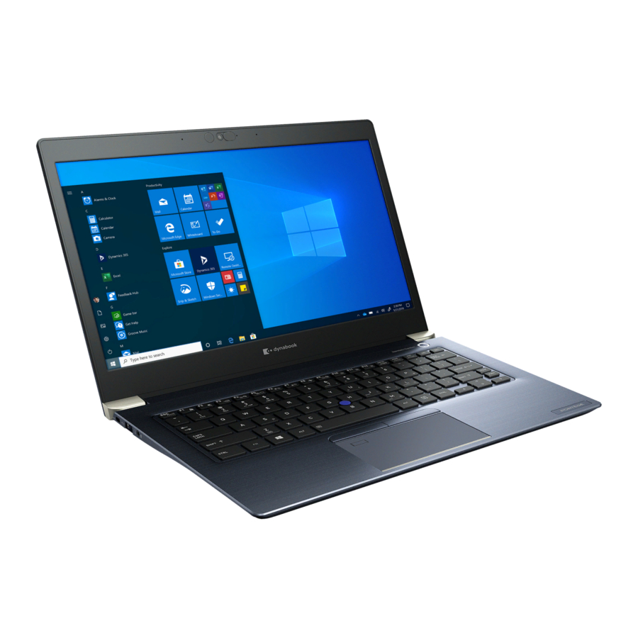
dynabook PORTEGE X40-J Series Manuals
Manuals and User Guides for dynabook PORTEGE X40-J Series. We have
3
dynabook PORTEGE X40-J Series manuals available for free PDF download: User Manual, Maintenance Manual, Service Manual
dynabook PORTEGE X40-J Series Maintenance Manual (155 pages)
Brand:
dynabook
| Category:
Laptop
| Size: 16 MB
Table of Contents
Table of Contents
5
Chapter 1 Hardware Overview
12
Features and System Unit Block Diagram
12
Figure 1-1 System Unit Configurations
13
Figure 1-2 System Unit Block Diagram
14
Ssd
15
Table 1-1 M.2 SSD Specifications (KIOXIA)
17
Table 1-2 M.2 SSD Specifications (Samsung)
17
Table 1-3 M.2 SSD Specifications (Phison)
17
Keyboard
18
Display
18
Figure 1-3 Keyboard
18
Power Supply
19
Figure 1-4 LCD Module
19
Table 1-4 LCD Module Specifications
19
Batteries
20
Table 1-5 Power Supply Output Rating
20
Table 1-6 Battery Specifications
21
Table 1-7 Time Required for Charges
21
AC Adaptor
22
USB Type-C Adapter
22
Table 1-8 Data Preservation Time
22
Table 1-9 AC Adaptor Specifications
22
Table 1-10 USB Type-C Adapter Specifications
23
Chapter 2 Troubleshooting Procedures
24
Troubleshooting
24
Troubleshooting Flowchart
25
Figure 2-1 Troubleshooting Flowchart (1/2)
26
Figure 2-2 Troubleshooting Flowchart (2/2)
27
Power Supply Troubleshooting
28
Table 2-1 DC In/Battery Indicator
29
Table 2-2 Power Indicator
29
Table 2-3 Error Code
30
Figure 2-3 Connection Check
31
System Board Troubleshooting
32
USB Troubleshooting
34
Table 2-4 Main Test Menu
34
Figure 2-4 Connection Check
35
SSD Troubleshooting
36
Keyboard Troubleshooting
37
Touch Pad (Click Pad) Troubleshooting
37
Display Troubleshooting
39
Wireless LAN + Bluetooth Troubleshooting
40
Sound Troubleshooting
41
Memory Media (SD Card) Slot Troubleshooting
43
Fingerprint Sensor Troubleshooting
44
Figure 2-5 Scan the Finger
44
Web Camera Troubleshooting
46
HDMI Port Troubleshooting
47
Figure 2-6 Connecting the HDMI out Port
47
USB Type-C Adapter Troubleshooting
48
Chapter 3 Tests and Diagnostics
51
Test Program for Maintenance
51
How to Execute the Test Program
52
Entry of the DMI Information
54
Heatrun Test
56
Main Test Menu
56
Memory Test
58
Hard Disk (&SSD) Test
59
Keyboard Test
60
LCD Panel Test
61
Battery Charge Test
62
Fan Test
62
Log Utility
62
Wireless Module Test
63
Sound Test
65
Setup
65
Battery off Mode Setting Tool
71
Chapter 4 Replacement Procedures
74
Safety Precautions
75
Table 4-1 the Case for the Following Example
75
Before You Begin
77
Disassembly Procedure
77
Assembly Procedures
78
Figure 4-1 Pressure Plate Connector/Spring Connector/Back Flip Connector
78
Tools and Equipment
79
Screw Tightening Torque
79
Grip Color
80
Screw Notation
80
Memory Media
80
Cover Assembly and Base Assembly
81
Figure 4-2 Inserting Memory Media
81
Figure 4-3 Removing the Base Assembly (1)
82
Figure 4-4 Removing the Base Assembly (2)
82
Figure 4-5 Installing the Base Assembly
83
Battery Pack
84
Figure 4-6 Releasing the Battery Pack
84
Memory Module
85
Figure 4-7 Removing the Memory Module(S)
85
Ssd
86
Figure 4-8 Seating the Memory Module
86
Figure 4-9 Removing the SSD
86
Smart Card Slot
87
Figure 4-10 Installing the SSD
87
Figure 4-11 Removing the Smart Card Slot (1)
88
Figure 4-12 Removing the Smart Card Slot (2)
88
Figure 4-13 Removing the Smart Card Slot (3)
89
Figure 4-14 Installing the Smart Card Slot
89
Dual Button Unit/Click Pad
90
Figure 4-15 Removing the Dual Button Unit/Click Pad (1)
90
Figure 4-16 Removing the Dual Button Unit/Click Pad (2)
90
Figure 4-17 Removing the Dual Button Unit/Click Pad (3)
91
Figure 4-18 Removing the Dual Button Unit/Click Pad (4)
91
Figure 4-19 Removing the Dual Button Unit/Click Pad (5)
92
Figure 4-20 Removing the Dual Button Unit/Click Pad (6)
92
Speaker
94
Figure 4-24 Removing the Speaker (1)
94
Figure 4-25 Removing the Speaker (2)
95
Figure 4-26 Installing the Speaker (1)
95
Wireless LAN Card
96
Figure 4-27 Installing the Speaker (2)
96
Figure 4-28 Removing the Wireless LAN Card
97
Figure 4-29 Installing the Wireless LAN Card (1)
98
Figure 4-30 Installing the Wireless LAN Card (2)
98
USB Board
99
Figure 4-31 Removing the USB Board
99
Fan
100
Fin
100
Figure 4-32 Removing the Fan
100
System Board
101
Figure 4-33 Removing the Fin
101
Figure 4-34 Removing the System Board (1)
103
Figure 4-35 Removing the System Board (2)
103
Figure 4-36 Removing the System Board (3)
104
Figure 4-37 Installing the System Board
104
Keyboard/Cover Assembly
105
Figure 4-38 Removing the Keyboard/Cover Assembly
105
LCD Assembly
107
Figure 4-39 Removing the LCD Unit (1)
108
Figure 4-40 Removing the LCD Unit (2)
109
Figure 4-41 Removing the LCD Unit (3)
109
Figure 4-42 Installing the LCD Unit (1)
110
Figure 4-43 Installing the LCD Unit (2)
111
Figure 4-44 Installing the LCD Unit (4)
112
Figure 4-45 Installing the LCD Unit (5)
112
Figure 4-46 Installing the LCD Unit (6)
113
Figure 4-47 Removing the Camera Module (1)
113
Camera Module/Wireless Antennas
114
Figure 4-48 Removing the Camera Module (2)
114
Figure 4-49 Removing the Camera Module (3)
114
Figure 4-50 Stick Wireless LAN Antennas
115
Figure 4-51 Arrange Wireless LAN Antenna Cables
115
Display Hinges
116
Figure 4-52 Installing the Camera Module
116
Figure 4-53 Removing the Display Hinges
117
Appendix A Handling the LCD Module
118
Precautions for Handling the LCD Module
118
Board Layout
122
Appendix B Board Layout
122
System Board (FSAPSY*) Front View
122
Figure B-1 System Board (FSAPSY*) Layout (Front
122
Table B-1 System Board (FSAPSY*) Connectors (Front
122
System Board (FSAPSY*) Back View
123
Figure B-2 System Board (FSAPSY*) Layout (Back
123
Table B-2 System Board (FSAPSY*) Connectors (Back
123
USB Board (FSAPCN*) Front View
124
USB Board (FSAPCN*) Back View
124
Figure B-3 USB Board (FSAPCN*) Layout (Front
124
Figure B-4 USB Board (FSAPCN*) Layout (Back
124
Table B-3 USB Board (FSAPCN*) Connectors (Front
124
Pin Assignments
125
Appendix C Pin Assignments
125
SYSTEM Board (FSAPSY
125
Table C-1 CN1410 Memory Connector (260-Pin
126
Table C-2 CN1900 M.2 SSD Interface Connector
129
Table C-3 CN2630 WLAN Interface Connector
131
Table C-4 CN3260 KB Interface Connector (30-Pin
132
Table C-5 CN3240 KB Backlight Interface Connector (4-Pin
132
Table C-6 CN3380 FAN Interface Connector (4-Pin
133
Table C-7 CN4800 USB Type-C Interface Connector (24-Pin
133
Table C-8 CN4821 USB Type-C Interface Connector (24-Pin
134
Table C-9 CN5590 HDMI Port (19-Pin
134
Table C-10 CN9540 Web Camera Interface Connector
135
Table C-11 CN5390 LCD Interface Connector
135
Table C-12 CN8021 Battery Connector (17-Pin
137
Table C-13 CN9510 Click Pad Interface Connector (10-Pin
137
Table C-14 CN9550 Fingerprint Sensor Interface Connector (6-Pin
137
Table C-15 CN2170 Smartcard Slot (10-Pin
138
Table C-16 CN6290 L/F Speaker Connector
138
Table C-17 CN9602 FSAPCN* Interface Connector
139
Table C-18 IS2142 Micro SD Card Interface Connector (13-Pin
139
USB Board (FSAPCN
140
Table C-19 J6320 Headphone/Microphone Jack (6-Pin
140
Table C-20 CN4850 USB Type-A Interface Connector
140
Table C-21 CN4860 USB Type-A Interface Connector
140
Table C-22 CN9801 FSAPSY* Interface Connector
141
Scan Codes
142
Table D-1 Scan Codes (Set 1 and Set 2
142
Table D-2 Scan Codes with Left Shift Key
146
Table D-3 Scan Codes in Numlock Mode
147
Table D-4 Scan Codes with Fn Key
147
Table D-5 Scan Codes in Overlay Mode
147
Table D-6 No.124 Key Scan Code
148
Table D-7 No.126 Key Scan Code
148
Appendix D Keyboard Scan/Character Codes
149
Key Layout
149
Appendix E Key Layout
149
United Kingdom (UK) Keyboard
149
United States (US) Keyboard
149
Figure E-1 UK Keyboard
149
Figure E-2 US Keyboard
149
Figure F-1 RGB Monitor Loopback Connector
150
LAN Loopback Connector
151
Figure F-2 LAN Loopback Connector
151
Appendix F Wiring Diagrams
152
BIOS Rewrite Procedures
152
Tools
152
Rewriting the BIOS
152
Appendix G BIOS Rewrite Procedures
154
EC/KBC Rewrite Procedures
154
Appendix H EC/KBC Rewrite Procedures
155
Reliability
155
Table I-1 MTBF
155
Advertisement
dynabook PORTEGE X40-J Series User Manual (159 pages)
Brand:
dynabook
| Category:
Laptop
| Size: 2 MB
Table of Contents
Table of Contents
2
Chapter 1 Legal, Regulatory, and Safety
4
Copyright, Disclaimer and Trademarks
4
Regulatory Information
5
Video Standard Notice
12
Openssl Toolkit License Issues
12
Freetype License Issues
15
ENERGY STAR® Program
18
Disposing of the Computer and the Computer's Battery
18
General Precautions
19
Safety Icons
22
Chapter 2 Getting Started
23
Equipment Checklist
23
Conventions
23
Using Your Computer for the First Time
24
Getting to Know Windows
28
Turning off the Power
31
System Recovery
34
Chapter 3 The Grand Tour
38
Front with the Display Closed
38
Left Side
38
Right Side
40
Back
41
Underside
41
Front with the Display Open
42
Internal Hardware Components
45
Power Condition Descriptions
47
Chapter 4 Operating Basics
48
Using the Touch Screen
48
Using the Touch Pad
49
Pointing Device
50
The Keyboard
52
Using the Fingerprint Sensor
55
Battery
56
Memory Media
60
Smart Card
63
HDMI™ out Port
64
USB Type-C™ Adapters
65
Wireless Display
70
Security Lock
70
Optional Accessories
71
Sound System and Video Mode
72
Chapter 5 Utilities and Advanced Usage
75
Utilities and Applications
75
Special Features
82
Troubleshooting
85
Problem-Solving Process
85
Hardware and System Checklist
88
Technical Support
99
Appendix Specifications
101
AC Power Cord and Connectors
102
Information for Wireless Devices
103
Information about Intel® AMT
114
Accessibility
117
Ease of Access for Dynabook Notebook
117
Legal Footnotes
120
Glossary
123
Index
126
Instruction Manual for Safety and Comfort
130
Introduction
132
Power
133
Safe Use of Product, Components and Accessories
133
Communication
140
Main Unit
143
Systems/Peripherals
150
Computer User Comfort Recommendations
155
Good Working Posture
155
Using the Product with an External Keyboard, Mouse or Monitor
156
Viewing Recommendations
156
Taking Breaks and Varying Tasks
157
Typing Style
157
Mobile Computing Tips
158
Seeking Additional Help
158
Transporting the Product
158
Check List
159
dynabook PORTEGE X40-J Series Service Manual (48 pages)
Brand:
dynabook
| Category:
Laptop
| Size: 6 MB
Table of Contents
Cover Assembly and Base Assembly
8
Battery Pack
11
Memory Module
13
Smart Card Slot
16
Wireless Lan Card
25
Usb Board
28
System Board
30
LCD Assembly
36
Display Hinges
45
Advertisement
Advertisement
Related Products
dynabook TECRA X40-F
dynabook PORTEGE X40-G
dynabook Portege X40L-K Series
dynabook PORTEGE X40-J-12Z
dynabook TECRA X40-F1430
dynabook PORTEGE X40-K
dynabook TECRA X40-E Series
dynabook PORTEGE X40-M
dynabook TECRA X50-F-12Q
dynabook PORTEGE X20W-E Series
dynabook Categories
Laptop
Desktop
Computer Hardware
Protection Device
More dynabook Manuals
Login
Sign In
OR
Sign in with Facebook
Sign in with Google
Upload manual
Upload from disk
Upload from URL