Sign In
Upload
Manuals
Brands
DUPLO SEIKO CORPORATION Manuals
Disc Duplicator
Duprinter DP-340
DUPLO SEIKO CORPORATION Duprinter DP-340 Manuals
Manuals and User Guides for DUPLO SEIKO CORPORATION Duprinter DP-340. We have
1
DUPLO SEIKO CORPORATION Duprinter DP-340 manual available for free PDF download: Service Manual
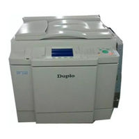
DUPLO SEIKO CORPORATION Duprinter DP-340 Service Manual (330 pages)
Brand:
DUPLO SEIKO CORPORATION
| Category:
Disc Duplicator
| Size: 6 MB
Table of Contents
Table of Contents
10
Introduction
2
Using the Service Manual
3
Cautions Regarding the Installation Location
4
Safety Instructions
4
Cautions for Installation Work
5
Cautions for Maintenance, Inspection and Servicing
6
Locations of Warning Stickers
7
Table of Contents
10
Chapter 1 Introduction
12
Introduction
12
Features
13
Specifications
15
Dimensions
17
System Setup
19
Part Names and Their Functions
20
Machine Exteriors
20
Chapter 2 Description of the Operation
23
Drum Driving Section
23
Drum Section
23
Sectional (Structural) View of the Machine
23
Control Panel
25
Operation Procedures
27
Platemaking & Printing
27
Multiple Image Printing / 2 in 1 Layout Mode
28
Paper Ejection Section
23
Paper Feed Section
23
Platemaking/Master Feed/Ejection Section
23
Press Section
23
Scanner Section
23
Chapter 2 Description of the Operation
29
Scanner Section
31
Description
31
Sequence of Operation
32
Sequence of the Scanner Operation
32
Sequence of the Scanner Operation (ADF)
32
Operation with the Document Cover Open / Closed
33
Reading the Document Darkness
33
Reading the Document Size
33
2Platemaking Area for the Book Shadow Erasing Mode
34
2Platemaking Area for the Selected Paper
34
Function of Parts and Circuit
35
Home Position Sensors
35
Document Sensor
36
Document Cover Sensor
38
CCD / Lamps
39
Scanner Unit Open / Close Detection
40
Platemaking / Master Feed / Ejection Section
41
Platemaking / Master Feed Section
41
Description
41
Sequence of Operation
42
Operation When the Master Set
42
Platemaking / Master Feeding
43
Function of Parts
44
Thermal Head
44
End Mark Sensor
47
Master End Detection
48
Master Setting Error Detection
48
Master Top Sensor
49
Master Detect Sensor
50
Cutter Unit
51
Master Feed Clutch(Electromagnetic Clutch)
52
Master Ejection Section
53
Description
53
Circuit
53
Function of Parts
54
Master Ejection Error Detection
54
Master Ejection Sensor
54
Rotation Control of the Eject(Roll-Up) Motor
54
Product No.: Initial Lot - 020455313
55
Master Clamp Opening/Closing Section
55
Description
55
Operation of Master Clamp Open / Close Lever
56
Structure
56
Master Attach / Detach Operation
57
Clamp Opening / Closing Lever Position (a / B / C Mode)
58
Function of Parts
59
A / B / C Mode Detect Sensor
59
Returning Operation Flowchart When the Power Is Cut off Accidentally
60
Product No.: 020455314
61
Master Clamp Opening/Closing Section
61
Description
61
Operation of Master Clamp Open / Close Lever
62
Structure
62
Master Attach / Detach Operation
63
Clamp Opening / Closing Lever Position (B / C Mode)
64
Function of Parts
65
B / C Mode Detect Sensor
65
Returning Operation Flowchart When the Power Is Cut off Accidentally
66
Paper Feed Section
67
Description
67
Operation
68
Rotation of the Paper Feed Roller and Timing Roller
68
Paper Feed Roller Drive
69
Driving of the Timing Roller
70
Escape the Guide Roller
71
Paper Feed Length
72
Function of Parts
73
Printing Position Adjustment Mechanism
73
Double Feed Detect Mechanism
75
Elevator Top Limit Sensor
76
Elevator Lower Limit Switch
77
Paper Sensor
78
Elavator Encoder Sensor
79
Long Paper Unit Mechanism (Option)
79
Drum Driving Section
80
Description
80
Function of Parts
81
Drum Stop / JAM Detect Position Sensor
81
Master Attach/Detach Position Sensor
82
JOG Switch 1,2(Drum Rotation Switch 1,2)
83
Control of the Main Motor
84
Rotation Speed Control by Encoder Sensor
85
Selecting the Speed
85
Press Section
86
Description
86
Press Roller Timing & Printing Area
86
Function of Parts
88
P-Roll Sensor
88
Switching the Contact Pressure
89
Contact Pressure Position Sensing
90
Paper Ejection Section
91
Description
91
Function of Parts
92
Paper Stripper Finger
92
Top Blow Fan
93
Paper Ejection Jam Sensor
94
Paper JAM Detection Timing
95
Paper Ejection Belt
96
Paper Ejection Belt Speed
96
Paper Aligning Mechanism
97
Drum Section
98
Description
98
Circuit
99
Function of Part
100
Ink Detection
100
LED Display and Output Signal on the Ink Detection PCB Unit
101
CHANGE INK" Display Timing
102
Ink Roller Up/Down Mechanism
103
Ink Pump
105
Drum Switch
106
Fine Start Mode
107
Drum Shift Mechanism
108
Front Cover Detection Switch
109
Tape Cluster
110
Chapter 3 Mechanism
111
Exterior
113
Removal of the Document Tray
113
Removal of
113
Removal of the Scanner Outer Cover
114
Removal of Rear Cover
115
Removal of Control Panel
117
Removal of Control Panel PCB
117
Removal of DC Regulated Power Supply
118
Removal of Drive PCB Unit and DC-DC PCB Unit
118
Scanner Section
119
Removal of Vertical Size Scale Plate
119
Removal of Glass
119
Removal of Inverter PCB Unit
120
Removal of Reading Cover
120
Removal of Lamp Unit
121
Removal of Lamp Cord
122
Removal of Slider a
123
Removal of Slider B
124
Removal of Scanner Unit
125
Platemaking / Master Feed and Ejection Section
126
Master Feed Section
126
Removal of Cutter Unit
126
Removal of End Mark Sensor PCB Unit
127
Removal of Thermal Head
128
Platemaking/Master Feed/Ejection Section
129
Removal of Master Feed Unit
129
Removal of Master Feed Stepping Motor
129
Master Ejection Section
130
Removal of Eject Motor(Roll-Up Motor)
130
Removal of Master Ejection Box
130
Removal of Master Ejection Sensor
130
Master Clamp Opening/Closing Section
131
Removal of Clamp Motor
131
Removal of Master Clamp Opening / Closing Unit
131
Removal of Timing Belt
132
Paper Feed Section
133
Removal of Elevator Lower Limit Switch
133
Removal of Paper Sensor
133
Removal of Paper Feed Roller
134
Removal of Paper Separator Unit
134
Removal of Paper Feed Unit
135
Removal of Paper Top Detect Sensor
135
Removal of Double Feed Detect Sensor
136
Removal of Long Paper Unit(LPU) [Option]
137
Removal of Timing Roller
137
Drum Driving Section
138
Removal of Sub-Frame
138
Removal of Drum Gear and Driving Assy
139
Removal of Drum Position Cam
139
Paper Ejection Section
140
Removal of Main Motor PCB Unit
140
Removal of Paper Stripper Finger / Sub Paper Stripper Finger
140
Removal of Paper Ejection Fan Unit
141
(Photo-Receiving PCB Unit)
142
Removal of Paper Ejection Belt
142
Removal of Fan/Jam Sensor (Photo-Emitting PCB Unit)
143
Removal of Top Blow Fan Unit
143
Removal of Press Motor
144
Removal of Pressure Adjustment Unit
144
Drum Section
145
Removal of Screen
145
Removal of Base Unit
146
Removal of Master Clamp
146
Removal of Outer Frame (Right) Unit
147
Removal of Outer Frame (Left) Assy
148
Removal of Inner Frame
149
Removal of Ink Motor
150
Removal of Ink Pump
150
Removal of Ink Detection PCB Unit
151
Removal of Ink Roller Up/Down Motor
151
Chapter 4 Standards / Adjustment
153
Scanner Section
155
Attaching the Rear Wire
155
Attaching the Front Wire
156
Adjusting the Timing Belt Tension
157
Platemaking / Master Feed / Ejection Section
157
Platemaking / Master Feed Section
157
Position Adjustment of Thermal Head Up/Down Motor
157
Attaching the Spring
158
Master Ejection Section
158
Adjusting the Timing Belt Tension
159
Adjusting the Timing Belt Tension
160
Master Clamp Opening/Closing Section
160
Positioning the Master Clamp Opening / Closing Levers
160
Adjusting the a / B / C Modes
161
Adjusting the Paper Separator Unit Clearance
165
Paper Feed Section
165
Adjusting the Elevator Top Limit Sensor
166
Adjusting the Paper Separation Pressure
166
Adjusting the Elevator Lower Limit Switch
167
Adjusting the Double Feed Detection Sensors
168
Adjusting the G Roll Escape Amount / Timing
168
Adjusting the Top/Bottom Position Sensors
169
Adjusting the Drum Stop Position
170
Drum Driving Section
170
Adjusting the Master Attach/Detach Position
171
Adjusting the P-Roll Sensor
172
Press Section
172
Adjusting the Printing Area (Press off Timing)
173
Adjusting the Paper Stripper Finger Clearance
174
Paper Ejection Section
174
Adjusting the Paper Stripper Finger Return Stopper
175
Adjusting the Ink Amount
176
Drum Section
176
Adjusting the Squeegee Gap
177
Adjusting the Master Clamp
178
Adjusting the Master Clamp Section
178
Adjusting the Drum Rail Gap
179
Adjusting Reduction / Enlargement
180
Adjusting the Longitudinal R/E on the Platemaking Side
180
Adjusting the Longitudinal R/E on the Reading Side
180
Electrical System
180
Adjusting the Lateral R/E on the Reading Side
181
Adjusting the Lateral (Operation Side) Reading Start Position
182
Adjusting the Top End Reading Start Position
182
Reading Start Position
182
Adjusting the Platemaking Start Position
183
When in Online
183
When the Scanner Is in Use
183
Adjusting the Document Reading Darkness
184
Adjusting the White Level of the Document Darkness
184
Adjusting the Reading Darkness
185
Adjusting of Printer Unit's Printing Speed
186
JOG Speed Adjustment
186
Pre-Stop Speed Adjustment
186
Adjustment of Printing Speeds 1-5
187
To Initialize Speed Settings
187
Adjustment of Eject Fan Speed
188
Adjustment of Eject Fan Speeds 1-5
188
To Initialize Speed Settings
188
Adjusting and Replacing the Upper / Lower Blade for the TAPE CLUSTER
189
Chapter 5 Maintenance/Check
190
Cleaning and Oiling
191
Guaranteed Periodical Maintenance
191
Periodical Maintenance
192
Chapter 6 Troubleshooting
194
Troubleshooting Guide
195
Countermeasures for the Defective Operation
195
Lamp Does Not Light up
196
Optical System Dose Not Move Forward/Backward.196
197
E001" Is Displayed
197
E002" Is Displayed
198
E005" Is Displayed
199
E006" Is Displayed
199
E008" Is Displayed
200
E009" Is Displayed
200
E011" Is Displayed
201
E013" Is Displayed
201
E014" Is Displayed
202
E016" Is Displayed
202
NO DRUM" Is Displayed
203
MASTER SETTING ERROR" Is Displayed
203
Malfunction of Master Feeding Clutch
204
Malfunction of Master Stepping Motor
204
PLATE EJECTION ERROR" Is Displayed
205
Malfunction of Roll-Up Motor
205
ADD PAPER" Is Displayed
206
FRONT COVER OPEN" Is Displayed
206
SCANNER OPEN" Is Displayed
207
CHANGE MASTER" Is Displayed
207
CHANGE INK" Is Displayed
208
PLEASE INSERT CARD" Is Displayed
208
PAPER JAM on the EJECTION SIDE" Is Displayed
209
PAPER JAM on the FEEDER SIDE" Is Displayed
210
Paper Jams in the Paper Feed Side
211
Paper Jams in the Paper Ejection Side
212
Error Display
213
Chapter 7 Help Mode
214
HELP Mode List
215
P Z HELP Mode List
215
Overview
219
HELP Mode Functions and Operation Procedures
220
Accessing HELP Modes
220
Guide to the HELP Mode Descriptions
220
Operation Procedures
220
HELP Mode Descriptions
221
Others
314
Chapter 8 Others
314
Electrical Parts Layout and Their Functions
315
Switches/Clutches/Solenoids
315
Sensors 1
316
Sensors 2
317
Motors/Fans
318
PCB Unit / Others
319
Connector VR/LED Layout and Functions
320
Overall Wiring Layout
326
Overall Wiring Layout 1( Main PCB )
326
Overall Wiring Layout 2( Drive PCB )
328
Advertisement
Advertisement
Related Products
DUPLO SEIKO CORPORATION Duprinter DP-460
DUPLO SEIKO CORPORATION Duprinter DP-440
DUPLO SEIKO CORPORATION Duprinter DP-430
DUPLO SEIKO CORPORATION Duprinter DP-330L
DUPLO SEIKO CORPORATION Duprinter DP-330
DUPLO SEIKO CORPORATION Categories
Disc Duplicator
More DUPLO SEIKO CORPORATION Manuals
Login
Sign In
OR
Sign in with Facebook
Sign in with Google
Upload manual
Upload from disk
Upload from URL