Table of Contents
Advertisement
Quick Links
N5-Y1071
2002.12
SERVICE MANUAL
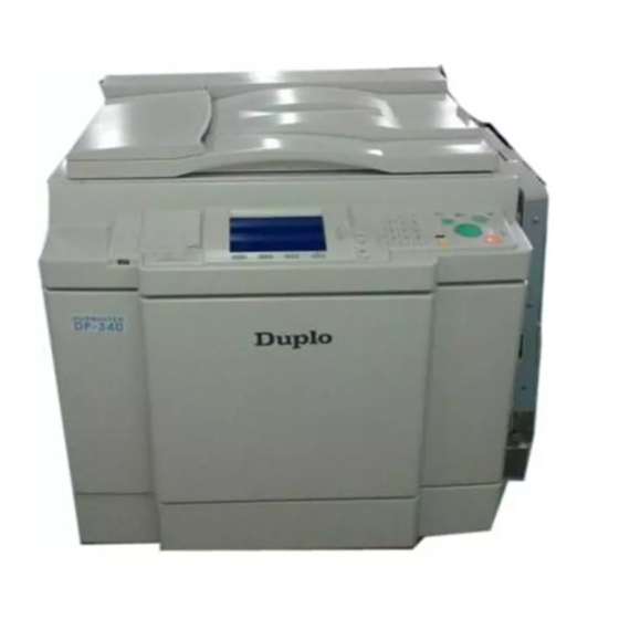
DUPRINTER
Ver.2
Be
sure
to
read
repair
and
service
correctly.
Do
not
thoroughly understood the contents of this manual.
Repairing or servicing the machine with insufficient
knowledge
about
accidents
or
falls
quality.
DP-460/DP-440
DP-430/DP-340
DP-330/DP-330L
this
manual
carefully,
this
machine
begin
work
until
it
could
lead
in
the
machine's
DUPLO SEIKO CORP.
so
that
you
safely
and
you
have
to
unforeseen
performance
or
Advertisement
Chapters
Table of Contents
Troubleshooting

Summary of Contents for DUPLO SEIKO CORPORATION Duprinter DP-460
- Page 1 SERVICE MANUAL DUPRINTER Ver.2 DP-460/DP-440 DP-430/DP-340 DP-330/DP-330L sure read this manual carefully, that repair service this machine safely correctly. begin work until have thoroughly understood the contents of this manual. Repairing or servicing the machine with insufficient knowledge about could lead unforeseen accidents...
-
Page 2: Introduction
When performing repair or service work not covered by this man- ual, you should obtain safety guidance from an appropriately knowledgeable person. Copyright 2002 DUPLO SEIKO CORPORATION All Rights Reserved... -
Page 3: Using The Service Manual
D Using the service manual • This manual contains the following information: structure and function of major parts, disassembly and reassembly procedures, specifications, and procedures for adjustment, maintenance, inspection and corrective action. This information is current as of December 2002, and applies basically to the model DP-460/440/430/340/330/330L DUPRINTER. From time to time, parts are changed to improve quality, performance or safety. -
Page 4: Cautions Regarding The Installation Location
Safety instructions Safety instructions 1. Cautions regarding the installation location Safety instructions Installation environment s Avoid installing the machine in places exposed to direct sunlight. • Sunlight will cause the temperature in the machine's interior to rise, possibly leading to malfunction of the control system. -
Page 5: Cautions For Installation Work
Safety instructions 2. Cautions for installation work Warning • The machine's power supply voltage and power consumption depend on the model. Details of this are given in the tables below. The power supply voltage and power consumption for the machine are given in the table below. -
Page 6: Cautions For Maintenance, Inspection And Servicing
Safety instructions 3. Cautions for maintenance, inspection and servicing Warning ' Precautions for safe servicing • Always remove the power cord plug from the outlet before starting work. a Otherwise, you could get a shock or your hands/fingers could be injured. •... -
Page 7: Locations Of Warning Stickers
Safety instructions DLocations of warning stickers The locations of the machine's warning stickers are shown below. To ensure safe work, read the stickers and heed their instructions. Keep the stickers clean at all times. If they become damaged or peel off, replace them with new ones. Do not remove this cover. - Page 8 Chapter 1 Introduction Chapter 2 Description of the Operation Chapter 3 Mechanism Chapter 4 Standard / Adjustment Chapter 5 Maintenance / Check Chapter 6 Troubleshooting Chapter 7 HELP Mode Chapter 8 Others...
-
Page 10: Table Of Contents
Table of Contents Introduction.................1 Chapter 4 Standards / Adjustment Using the service manual ............2 Safety instructions ...............3 z Scanner Section............154 1.Cautions regarding the installation location......3 x Platemaking/Master Feed/Ejection Section...156 2.Cautions for installation work ..........4 c Paper Feed Section ..........164 3.Cautions for maintenance, inspection and servicing ..5 v Drum Driving Section ..........169 •... -
Page 12: Introduction
Chapter 1 Introduction z Features ................12 x Specifications...............14 c Dimensions..............16 v System Setup ...............18 b Part Names and Their Functions........19 1. Machine exteriors............19 2. Sectional (structural) view of the machine ...22 3. Control Panel ............24 n Operation Procedures ..........26 1. Platemaking & Printing ...........26 2. -
Page 13: Features
chap.1 z Features zFeatures Size A3/B4 printing(Printing area) Full range of necessary functions DP-460/440/430 : A3 ( 290X423mm ) Documents are easily enlarged or reduced. DP-340/330/330L : B4 ( 250X355mm ) In addition to same-size printing, there are three automatic settings for both enlargement and High-speed platemaking reduction. - Page 14 chap.1 z Features Document modes Special functions The "Text-Photograph", "Text-Fine Lettering", The HELP mode items listed below can now also be "Photograph-Fine Lettering", "Screen 1 & 2" and used in the user mode. And the power save mode can "Photo Dark" Modes selecting, accommodating cut power consumption.
-
Page 15: Specifications
chap.1 x Specifications xSpecifications • Specifications * Specifications are subject to change without notice. Model name DUPRINTER DP-460 DP-440 DP-430 DP-340 DP-330 DP-330L Model Floor model Master making method Thermal digital master making Master making interval 24 sec ( A4R 100% ) 19 sec ( A4R 100% ) 24 sec ( A4R 100% ) 19 sec ( A4R 100% ) - Page 16 Specifications * Specifications are subject to change without notice. DUPRINTER DP-460/440/430/340/330/330L Model name Other function Image Rotation ( 90 & 180 degree) Colour Separation (equipped in online printer driver) Document Size Auto Scan Multiple Exposure ( 2, 4, 8, & 16- up.) Book Shadow Erasure ( adjustable) Memory Function ( 9 pattern of settings of control panel can be stored.)
-
Page 17: Dimensions
chap.1 c Dimensions cDimensions 226.5 483.5 1330 ( mm ) 44000B... - Page 18 chap.1 c Dimensions MEMO...
-
Page 19: System Setup
chap.1 v System Setup vSystem Setup 1. Before Installation The machine and its optional equipment are set up as follows: S2-ADF KEYCARD COUNTER 4 Duplo Direct Print System TAPE CLUSTER 4 Personal computer Cabinet (Printer stand) Drum unit A3/A4 drum (Attachable to DP-460/440/430 only) : Option 44000C DDP system... -
Page 20: Part Names And Their Functions
chap.1 b Part Names and Their Functions bPart Names and Their Functions 1. Machine exteriors Document cover Glass Vertical size scale plate Control panel Panel cover Contrast adjusting dial Scanner switch Feed tray descend switch (Elevator down switch) Inlet Feed tray Feed pressure adjuster lever Supplemental... - Page 21 chap.1 b Part Names and Their Functions Master feed section Master ejection section Platen roller Cutter Thermal head Master roll cut switch Master ejection core Master ejection box lid release lever Master ejection box lever JOG switch 1 (Drum rotator switch 1) Drum section Drum bar Drum handle...
- Page 22 chap.1 b Part Names and Their Functions Jump plate Top blow fun Paper stacker guide JOG switch 2 Print tray (Drum rotator switch 2) Paper aligning lever Paper stopper S2-ADF connector cover (Optional) Interface kit II (Optional) Connectors (Optional) 440CCe...
-
Page 23: Chapter 2 Description Of The Operation
chap.1 b Part Names and Their Functions 2. Sectional (structural) view of the machine Description of Section Name Mechanism Srandard/Adjustment the Operation Scanner section 30page 118page 154page Platemaking/Master feed/ejection section 40page 125page 156page Platemaking/Master feed section 40page 125page 156page Master ejection section 52page 129page 157page... - Page 24 chap.1 b Part Names and Their Functions 44000A1e...
-
Page 25: Control Panel
chap.1 b Part Names and Their Functions 3. Control Panel 2Keys inside of the panel cover 94 % Name Function EDIT key Switches to rotate the document image for plate. Enables confidential safeguard function. CONFIDENTIAL SAFEGUARD key Prints cannot be made unless a new master is made. USER SETTING key Switches to User setting list display. - Page 26 chap.1 b Part Names and Their Functions Name Function Displays current settings and status of the machine e.g. print volume, and error messages in case of error. Cursor keys Selects setting item and adjusts printing position. OK key Enters specified setting. Ten keys Enter the print volume etc.
-
Page 27: Operation Procedures
chap.1 n Operation Procedures nOperation Procedures 1. Pratemaking & Printing ZOOM Selects Text , Photograph , IMAGE MODE Text / Photograph Mode MULTIPLE EXPOSURE MASTER DARKNESS BOOK SHADOW ERASER TEST PRINT... -
Page 28: Multiple Image Printing / 2 In 1 Layout Mode
chap.1 n Operation Procedures 2. Multiple Image Printing / 2 IN 1 Layout Mode In the normal state (when the ADF is not connected) the mode is switched by pressing the multiple printing selection key as follows. NOTE : Each press of the multiple printing selection key makes a different multiple printing indicator light up, in sequence. - Page 29 Chapter 2 Description of the Operation z Scanner Section............30 Master Ejection Section ...........52 1. Description...............30 1. Description...............52 2. Sequence of Operation ...........31 2. Circuit ...............52 (1) Sequence of the Scanner Operation ....31 3. Function of Parts ............53 (2) Sequence of the Scanner Operation (ADF) ..31 (1) Master Ejection Sensor ........53 (3) Operation with the Document 1.
- Page 30 c Paper Feed Section .............66 n Paper Ejection Section..........90 1. Description...............66 1. Description...............90 2. Operation ..............67 2. Function of Parts ............91 (1) Rotation of the Paper Feed Roller and (1) Paper Stripper Finger ........91 Timing Roller .............67 (2) Top Blow Fan ............92 (2) Paper Feed Roller Drive........68 (3) Paper Ejection Jam Sensor .......93 (3) Driving of the Timing Roller......69...
-
Page 31: Scanner Section
chap.2 z Scanner Section zScanner Section 1. Description The document is illuminated with the lamps, and the document reflection in proportion to the document image darkness is imaged on the CCDs through the mirror and lens. Then it is resoluted into picture elements and converted photoelectrically.Additionally the machine is equipped with 3 reflecting sensors that sense the size of documents placed on the document glass. -
Page 32: Sequence Of Operation
chap.2 z Scanner Section 2. Sequence of Operation (1) Sequence of the Scanner Operation (with ADF unconnected) 1) When the PLATEMAKING key is pressed, the Image reading begins optical system moves to the left and reads the image. 440344 2) When image reading is complete, the lamp goes Image reading out, but the optical system decelerates, then stops. -
Page 33: Operation With The Document Cover Open / Closed
chap.2 z Scanner Section Operation with the Document Cover Open / Closed When the document cover is opened at a certain angle, the document cover position sensor changes to be in the state of photopassing. The lamps lights up. When the document cover is closed at a certain angle, the document cover position sensor changes to be in the state of photointerrupting. -
Page 34: 2Platemaking Area For The Selected Paper
chap.2 z Scanner Section NOTE Platemaking Area for the Selected Paper 2The platemaking area varies depending on the selected paper size as shown below. Selected paper size Remarks 290A 414A DP-460/440/430 DP-460/440/430 11"914" DP-330L STMT DP-460/440/430 MINI * When the magnification error is 0 in the primary scanning or in the secondary scanning, the size for the same size (1:1) platemaking is shown. -
Page 35: Function Of Parts And Circuit
chap.2 z Scanner Section 3. Function of Parts and Circuit (1) Home Position Sensors Description PS1 detects the optical system home position when ADF is not used. PS2 detects the optical system home position when ADF is used. Circuit Scanner home position sensor ( PS1) Photopassing Photointerrupting:5V CN11-1... -
Page 36: Document Sensor
chap.2 z Scanner Section (2) Document Sensors Description Document sensors 1, 2 and 3 (primary scanning) sense the document's length in the primary scanning when it is placed on the document glass. Document sensor 4 (secondary scanning) / document sensor 5 (secondary scanning) senses the document's length in the secondary scanning when it is placed on the document glass. - Page 37 chap.2 z Scanner Section Circuit Document sensor 1,2,3 (primary scanning) CN12-1 Paper present :0V Light blue Light blue No paper Light green Light green Pink Pink Blue Blue Paper present :0V Document sensor 4 (secondary scanning) No paper CN12-6 Green Green Blue Blue...
-
Page 38: Document Cover Sensor
chap.2 z Scanner Section (3) Document Cover Position Sensor Description The document cover position sensor detects opening and closing of the document cover (or ADF if the ADF is installed). Circuit Document cover position sensor Photopassing Photointerrupting:5V CN6-1 Light green Light green Blue Blue... -
Page 39: Ccd / Lamps
chap.2 z Scanner Section (4) CCD / Lamp Description The lamp illuminates the document and the reflected light is transmitted onto the CCDs.The CCDs output the image signals in level of voltage. Circuit La mp Lam p i nver t e r un i t D r i ve P C B u ni t CN1-1 Gray... -
Page 40: Scanner Unit Open / Close Detection
chap.2 z Scanner Section (5) Scanner Unit Open / Close Detection Description Opening and closing of scanner unit cover is detected by scanner unit cover open / close detection SW (MS3). This machine does not work (except for the master cut SW and the jog SW) unless the scanner unit is closed firmly. -
Page 41: Platemaking / Master Feed / Ejection Section
chap.2 x Platemaking / Master Feed / Ejection Section xPlatemaking / Master Feed / Ejection Section See page 52 See page 54 Master Clamp Opening / Platemaking / Master Feed section Master Ejection Section Closing Section 440315 Platemaking / Master Feed Section 1. -
Page 42: Sequence Of Operation
chap.2 x Platemaking / Master Feed / Ejection Section 2. Sequence of Operation (1) Operation when the master set Switch ON Platen roller When the master cover is closed, the platen roller and sponge roller1 rotate and feed out the master for 10 seconds. Sponge roller 1 440346 When the Master top sensor is interrupted, the... -
Page 43: Platemaking / Master Feeding
chap.2 x Platemaking / Master Feed / Ejection Section (2) Platemaking / Master Feeding Operation When platemaking operation starts, the drum unit rotates to perform master removal process. The drum which has finished master removal process stops at the master set position. 63S00211 Open the master clamp. -
Page 44: Function Of Parts
chap.2 x Platemaking / Master Feed / Ejection Section 3. Functions of Parts (1)Thermal Head Description The thermal elements are in alignment in the primary scanning, and are heated on the image section to make holes on the master film. Circuit Thermal head DC-DC PCB unit... - Page 45 chap.2 x Platemaking / Master Feed / Ejection Section Exterior and Lot No. 0.5(DP-460/440), 309 0.2(DP-430), 276.5 0.5(DP-340), 276.0 0.2(DP-330/330L) 292.57 0.1(DP-460/440), 292.7 0.1(DP-430), 260.1 0.1(DP-340), 260.16 0.1(DP-330/330L) Thermal resistor line Thermistor Label :DP-460 / 440 / 340 Label :DP-430 / 330 / 330L Power connector Signal connector Pin (No.1)
- Page 46 chap.2 x Platemaking / Master Feed / Ejection Section NOTE : Resistance Resistance value is described on the label. When the head is replaced and the HELP mode is initialized, set the DIP-SW (H-43,H-44) of the HELP mode. HELP mode H-43,44 \ see p.272 - 274 Label :DP-460 / 440 / 340 Lank Resistance value...
-
Page 47: End Mark Sensor
chap.2 x Platemaking / Master Feed / Ejection Section (2) End Mark Sensor Description End mark sensor The end marks are located at a fixed distance relative to the master; as the master is being fed, the end mark sensor senses master condition and B4 model: the end marks by means of intensity of reflected DP-340/330/330L... -
Page 48: Master Setting Error Detection
chap.2 x Platemaking / Master Feed / Ejection Section 1. Master Setting Error Detection Operation In platemaking, the end mark sensor uses amount of reflected light to detect presence or absence of a master on the transfer path. Then the following displays and operations are performed: 2When a master setting error is detected, "MASTER SETTING ERROR"... -
Page 49: Master Top Sensor
chap.2 x Platemaking / Master Feed / Ejection Section (3) Master top sensor Description The master top sensor is located at a fixed distance Master relative to the master. By means of reflected light, this sensor senses the presence of the master on the master travel path. -
Page 50: Master Detect Sensor
chap.2 x Platemaking / Master Feed / Ejection Section (4) Master Detect Sensor Description Master detect sensor The master detect sensor is located at a fixed distance relative to the drum. By means of reflected light, this sensor senses master setting errors. When a master setting error occurs, "MASTER SETTING ERROR"... -
Page 51: Cutter Unit
chap.2 x Platemaking / Master Feed / Ejection Section (5) Cutter Unit Description Completed, the stepping motor for platemaking and the drum stops temporarily, the cutter motor is turned on to drive the cutter and the master is cut. Circuit Cutter motor(M5) Drive PCB unit Black... -
Page 52: Master Feed Clutch(Electromagnetic Clutch)
chap.2 x Platemaking / Master Feed / Ejection Section (6) Master Feed Clutch(Electromagnetic clutch) Description Sponge roller2 is attached to the bottom section of the master conveyance way of the master feed unit, and is driven via the master feed clutch (CL1) by the platemaking motor. The rotation of sponge roller2 is controlled with the master feed clutch ON / OFF. -
Page 53: Master Ejection Section
chap.2 x Platemaking / Master Feed / Ejection Section Master Ejection Section 1. Description When the drum stops at the plate detachment position and the master clamp which clamps the master tip end is opened (C mode), the pulling roller on the rolling section of the master ejection box pulls the master tip end into the box inside, and the master is rolled up to the core. -
Page 54: Function Of Parts
chap.2 x Platemaking / Master Feed / Ejection Section 3. Function of Parts (1) Master Ejection Sensor Description 2HELP mode H-06 value Photo-emission from the master ejection sensor is received on the master ejection sensor, and the sensor detects with the photo strength whether the master is pulled to the master ejection box. -
Page 55: Product No.: Initial Lot - 020455313
chap.2 x Platemaking / Master Feed / Ejection Section Master Clamp Opening / Closing Section Product No.: initial lot - 020455313 1. Description The master clamp on the drum unit is opened or closed by the two opening / closing levers' rotation operation. The opening / closing levers (one for the master attach position, and the other for the master detach position) are on the master clamp opening / closing section on the main body rear side. -
Page 56: Operation Of Master Clamp Open / Close Lever
chap.2 x Platemaking / Master Feed / Ejection Section Product No.: initial lot - 020455313 2. Operation of Master Clamp Open / Close Lever (1) Structure The following is the structure of the master clamp opening / closing section viewed with the rear cover opened. The rotation stop position of the master clamp opening / closing lever is determined by the clamp motor and two cams. -
Page 57: Master Attach / Detach Operation
chap.2 x Platemaking / Master Feed / Ejection Section Product No.: initial lot - 020455313 (2) Master Attach / Detach Operation The drum rotates to the master detach position Stop The drum rotates to the master attach position Stop... -
Page 58: Clamp Opening / Closing Lever Position (A / B / C Mode)
chap.2 x Platemaking / Master Feed / Ejection Section Product No.: initial lot - 020455313 (3) Clamp Opening / Closing Lever Position (A / B / C Mode) Mode Photointerrupter stop position / state of sensor Functions A / C mode detect sensor In the normal state or during printing, the master clamp opening / closing lever turns out from the master clamp opening / closing... -
Page 59: Function Of Parts
chap.2 x Platemaking / Master Feed / Ejection Section Product No.: initial lot - 020455313 3. Function of Parts (1) A / B / C Mode Detect Sensor Circuit Clamp motor Drive PCB unit Yellow CN9-26 Orange A/C mode detect sensor CN17-3 Orange Blue... -
Page 60: Returning Operation Flowchart When The Power Is Cut Off Accidentally
chap.2 x Platemaking / Master Feed / Ejection Section Product No.: initial lot - 020455313 4. Returning Operation Flowchart When the Power Is Cut Off Accidentally The machine returns to the initial state automatically when the power is turned off mistakenly during pro- cessing platemaking, master detach and master attach simultaneously or when the power returns after it is interrupted. -
Page 61: Product No.: 020455314
chap.2 x Platemaking / Master Feed / Ejection Section Master Clamp Opening / Closing Section Product No.: 020455314 - 1. Description The master clamp on the drum unit is opened or closed by the two opening / closing levers' rotation operation. The opening / closing levers (one for the master attach position, and the other for the master detach position) are on the master clamp opening / closing section on the main body rear side. -
Page 62: Operation Of Master Clamp Open / Close Lever
chap.2 x Platemaking / Master Feed / Ejection Section Product No.: 020455314 - 2. Operation of Master Clamp Open / Close Lever (1) Structure The following is the structure of the master clamp opening / closing section viewed with the rear cover opened. The rotation stop position of the master clamp opening / closing lever is determined by the clamp motor and two cams. -
Page 63: Master Attach / Detach Operation
chap.2 x Platemaking / Master Feed / Ejection Section Product No.: 020455314 - (2) Master Attach / Detach Operation The drum rotates to the master detach position Stop The drum rotates to the master attach position Stop... -
Page 64: Clamp Opening / Closing Lever Position (B / C Mode)
chap.2 x Platemaking / Master Feed / Ejection Section Product No.: 020455314 - (3) Clamp Opening / Closing Lever Position (B / C Mode) Mode Photointerrupter stop position / state of sensor Functions B mode detect The master clamp opening / closing lever C mode detect sensor sensor pinch the master clamp opening / closing... -
Page 65: Function Of Parts
chap.2 x Platemaking / Master Feed / Ejection Section Product No.: 020455314 - 3. Function of Parts (1) B / C Mode Detect Sensor Circuit Clamp motor Drive PCB unit Yellow CN9-26 Orange C mode detect sensor CN17-3 Orange Blue Photopassing Photointerrupting:5V B mode detect sensor... -
Page 66: Returning Operation Flowchart When The Power Is Cut Off Accidentally
chap.2 x Platemaking / Master Feed / Ejection Section Product No.: 020455314 - 4. Returning Operation Flowchart When the Power Is Cut Off Accidentally The machine returns to the initial state automatically when the power is turned off mistakenly during pro- cessing platemaking, master detach and master attach simultaneously or when the power returns after it is interrupted. -
Page 67: Paper Feed Section
chap.2 c Paper Feed Section cPaper Feed Section 1. Description Feeding of the paper is performed by the paper separator (employing the center separation method) and paper feed roller (there is no corner finger). Elevation of the feed tray is powered by the elevator motor.The paper top detect sensor is equipped at the rear of the paper feed roller. -
Page 68: Operation
chap.2 c Paper Feed Section 2. Operation (1) Rotation of the Paper Feed Roller and Timing Roller When the main motor turns, the paper feed cam rotates, causing the paper feed segment and timing segment to execute the reciprocating motion shown below, which turns the pinion gear. Paper feed segment Paper feed cam Paper feed roller... -
Page 69: Paper Feed Roller Drive
chap.2 c Paper Feed Section (2) Paper Feed Roller Drive The paper feed roller is driven by the paper feed stepping motor via the timing belt. The rotational timing is controlled by the program. Timing belt Paper feed stepping motor Paper feed roller 440303... -
Page 70: Driving Of The Timing Roller
chap.2 c Paper Feed Section (3) Driving of the Timing Roller Timing roller is actuated to rotate by the pinion gear and spring clutch. When the paper feed cam rotates, the reciprocating motion of the timing roller segment is transmitted to the pinion gear, and the spring clutch works to rotate the Timing roller in the direction of conveyance. -
Page 71: Escape The Guide Roller
chap.2 c Paper Feed Section (4) Escape the Guide Roller After the Press roller is pressed to the drum, the printing paper is gripped firmly with the drum and Press roller, the Guide roller is released from the Timing roller. This is called "escaped". Escape timing is within a period when the printing paper is conveyed about 10 mm after it is gripped with the drum and Press roller. -
Page 72: Paper Feed Length
chap.2 c Paper Feed Section (5) Paper Feed Length The “paper feed length” is the length by which the paper feed roller feeds out the print paper. When the paper feed roller feeds out the print paper, the guide roller is pressed against the timing roller and does not rotate; as a result, the paper arches up between the paper separator and the timing roller, since the distance between these two items is only 80mm, while the length by which the paper is fed out from the paper feed roller is 95mm. -
Page 73: Function Of Parts
chap.2 c Paper Feed Section 3. Functions of parts (1) Printing Position Adjusting Mechanism The printing position is adjusted by changing the ADJUST timing of the paper toward the drum with the PRINTING POSITION key on the control panel. PRINT POS. Description When the PRINTING POSITION key on the control panel is pressed, the link cam is driven by the... - Page 74 chap.2 c Paper Feed Section Circuit Top/bottom motor(M6) Drive PCB unit Orange CN9-3 Yellow Top/bottom center sensor Photopassing Photointerrupting:5V White Blue Top/bottom encoder sensor Photopassing CN20-1 Photointerrupting:5V Black Blue Main PCB unit 440W15e Operation Top and bottom limit of print position is detected by the top/bottom encoder sensor and the center sensor.
-
Page 75: Double Feed Detect Mechanism
chap.2 c Paper Feed Section (2) Double Feed Detect Mechanism Description The double feed detect sensor is mounted at the rear of the paper lead edge sensor to detect feeding of multiple papers. When it is detected, “DOUBLE FEEDING ERROR” is displayed on the LCD. If double feeding occurs with the tape cluster (optional) equipped, the tape is inserted. -
Page 76: Elevator Top Limit Sensor
chap.2 c Paper Feed Section (3) Elevator Top Limit Sensor Description The elevator top limit sensor senses decrease of the paper pile, and the top limit position of the feed tray. It does so by detecting the up/down motion of the paper feed shaft. Circuits Elevator top limit sensor(PS9) Photopassing... -
Page 77: Elevator Lower Limit Switch
chap.2 c Paper Feed Section (4) Elevator lower limit SWitch Description This is a micro switch that senses the lower limit position of the feed tray. Circuits Elevator lower limit switch descent(push):OPEN Light blue CN4-20 Light blue Ma i n P C B u ni t 440W17e Operation When the feed tray rises, the bracket disengages from the switch and the switch closes. -
Page 78: Paper Sensor
chap.2 c Paper Feed Section (5) Paper Sensor Description Senses presence/absence of paper in the feed tray. When the paper in the tray runs out, the message "ADD PAPER" is displayed and printing stops. Circuits Paper sensor paper present : CLOSE paper absent : OPEN Photopassing Photointerrupting:5V... -
Page 79: Elavator Encoder Sensor
chap.2 c Paper Feed Section (6) Elavator Encoder Sensor Description The encoder sensor detects rotation of the elevator motor. If the encoder sensor does not detect "photopassing \ photointerrupting" or "photointerrupting \ photopassing" within 2 seconds of sending of the elevator drive signal, the error "E002"... -
Page 80: Drum Driving Section
chap.2 v Drum Driving Section vDrum Driving Section 1. Description Drum position cam Drum gear Drum stop / JAM detect position sensor Master attach/detach position sensor Main motor Encoder Main motor encoder sensor 440320... -
Page 81: Function Of Parts
chap.2 v Drum Driving Section 2. Function of Parts (1) Drum Stop / JAM Detect Position Sensor The drum stop / JAM detect position sensor detects the drum stop position and JAM detect position. 2The drum stop position is the position where the drum stops at the same time when a beep sounds after the JOG switch (drum rotation switch) is kept pressing. -
Page 82: Master Attach/Detach Position Sensor
chap.2 v Drum Driving Section (2) Master Attach/Detach Position Sensor The master attach/detach position sensor detects the drum stop position when the plate is attached or detached. It also detects the speed reducing timing for stopping at the printing speed and for pressing the JOG switch (drum rotation switch ) . -
Page 83: Jog Switch 1,2(Drum Rotation Switch 1,2)
chap.2 v Drum Driving Section (3) JOG Switch 1,2 (Drum Rotation Switch 1,2) Description The drum rotates as long as the JOG switch (drum rotation switch) is pressed (within one rotation) and stops at the stop position with a beep.When the drum stops there, the LED mounted on the JOG switch 1 will light up. Circuit Drum rotation 1 switch CN4-8... -
Page 84: Control Of The Main Motor
chap.2 v Drum Driving Section (4) Control of the Main Motor Circuit Main motor PCB unit Brown CN4-1 Terminal plate(+24) Brown DC24V Blue Blue Terminal plate(GND) Main motor encoder sensor(PS7) CN1-1 Gray Blue Main motor(M1) CN5-1 Blue M ai n P C B un i t 440W22e... -
Page 85: Rotation Speed Control By Encoder Sensor
chap.2 v Drum Driving Section 1. Rotation Speed Control by Encoder Sensor The encoder sensor detects the main motor rotation. The main motor PCB Unit controls the number of main motor rotations with the encoder sensor signal. The encoder sensor signal is transmitted to the main PCB Unit as encoder dividing signal (8 dividings). -
Page 86: Press Section
chap.2 b Press Section bPress Section 1. Description Drum gear Press lever P-roll sensor Cancel lever Cancel lever Press roller Paper Signal solenoid Contact pressure unit 440308 (1) Press Roller Timing & Printing Area Description In this machine, the master is rolled up to the drum, ink is transferred to the drum and the printing paper is pressed to the drum by the press roller to print. - Page 87 chap.2 b Press Section The press roller is ON (the press roller is pressed to the drum) or OFF by operating the press lever up and down with the cam inside the drum gear. Press roller : OFF Press roller : ON Cancel lever Press lever Press roller...
-
Page 88: Function Of Parts
chap.2 b Press Section 2. Function of Parts (1) P- roll Sensor The P- roll sensor detects up and down of the press roller. The press roller only ascends when the paper is fed from the paper feed section by the cancel lever. The P- roll sensor also is used to know whether the paper is fed. -
Page 89: Switching The Contact Pressure
chap.2 b Press Section (2) Switching the Contact Pressure The contact pressure can be switched on the operation panel. When it is changed on the operation panel, the press motor will start up to effect the switch as soon as the PRINT key is pressed. -
Page 90: Contact Pressure Position Sensing
chap.2 b Press Section 1. Contact pressure position sensing 2Low contact pressure position: Sensed by pressure center switch. Switch turns from OFF to ON in response to Drum unit movement in the direction of the arrow. Press roller Pressure center switch 440362 2Standard contact pressure position: Sensed by pressure center switch. -
Page 91: Paper Ejection Section
chap.2 n Paper Ejection Section nPaper Ejection Section 1. Description In the paper ejection section the printed paper is removed from the drum and is ejected to the print tray. Escape cam Top blow fan Paper ejection JAM sensor(Photo-emitting) Paper stripper finger Top blow fan unit Paper ejection fan Paper ejection motor... -
Page 92: Function Of Parts
chap.2 n Paper Ejection Section 2. Functions of Parts (1) Paper Stripper Finger Mechanical Structure and Operation In addition to the paper stripper finger installed in the center, there are two sub paper remover fingers on both sides. There is an air diffuser on the tip of the finger. Compressed air transmitted from the air pump is blowed out of this hole to detach the tip end of the paper from the drum. -
Page 93: Top Blow Fan
chap.2 n Paper Ejection Section (2) Top Blow Fan Circuit Top brow fan 1 CN10-1 Black Top brow fan 2 Black Drive PCB unit 440W26e Operation During printing, the fan blows a constant stream of air at the paper stripper finger, from the rear. This assists paper stripping and also presses the paper against the ejection belt, which stabilizes ejection. -
Page 94: Paper Ejection Jam Sensor
chap.2 n Paper Ejection Section (3) Paper Ejection JAM Sensor Description The JAM sensor photo-receiving element is installed on the paper ejection fan unit and detects whether the paper is ejected normally. When it is detected that the paper is not ejected normally, "PAPER JAM ON THE EJECTION SIDE"... -
Page 95: Paper Jam Detection Timing
chap.2 n Paper Ejection Section 1. Paper Jam Detection Timing Description Paper jamming is divided into two types: "PAPER JAM ON THE EJECTION SIDE" and "PAPER JAM ON THE FEEDER SIDE". Paper jamming is detected under the following conditions. When paper jamming is detected, "PAPER JAM"... -
Page 96: Paper Ejection Belt
chap.2 n Paper Ejection Section (4) Paper Ejection Belt Description The paper ejection belt takes the paper stripped off the drum by the paper stripper finger to the print tray. The belt is driven by the paper ejection motor. Its speed is sensed by an eject fan encoder sensor. Paper ejection motor Paper ejection belt Eject fan encoder sensor... -
Page 97: Paper Aligning Mechanism
chap.2 n Paper Ejection Section (5) Paper aligning mechanism Description Paper can be aligned neatly by considering the ejection angle. Adjustments should be made in accordance with paper thickness. For thinner paper: Set the lever in the upper position. For thicker paper: Set the lever in the lower position. * Although the lever is usually set at the intermediate position for paper of normal thickness (65g/m ), the lever position should be adjusted depending on the condition of the paper. -
Page 98: Drum Section
chap.2 m Drum Section mDrum Section 1. Description The ink control section is in the drum unit. The ink control section is supplied with ink in the ink pack attached to the drum unit by the motor. The ink control section has an ink detection function, and is always supplied with a fixed amount of ink. -
Page 99: Circuit
chap.2 m Drum Section 2. Circuit Black CN14-1 Drive PCB unit Sideways stepping motor Light green Pink Blue Yellow White Ink roller up/down motor Brown CN14-7 White Ink roller motor Green CN12-1 Brown Ink detection PCB unit +23V Blue CN1-3 Brown Black Drum limit sensor... -
Page 100: Function Of Part
chap.2 m Drum Section 3. Function of Parts (1) Ink Detection Description The ink amount variation in the ink control section is read by the electric capacity variation between the detection needles on the ink detection PCB Unit and the GND and the ink signal is output to the main PCB Unit. -
Page 101: Led Display And Output Signal On The Ink Detection Pcb Unit
chap.2 m Drum Section 1. LED Display and Output Signal on the Ink Detection PCB Unit 2When the electric capacity variation between the detection needles on the ink detection PCB Unit and GND is over the threshold value, the LED on the ink detection PCB Unit lights up and the ink signal (0V) is output. -
Page 102: Change Ink" Display Timing
chap.2 m Drum Section 2. "CHANGE INK" Display Timing When HIGH (5V) is output by detecting ink while the drum continues to rotate 20 times (the number of rotations varies depending on the printing speed.*) during printing, it is detected that the ink pack is empty, "CHANGE INK"... -
Page 103: Ink Roller Up/Down Mechanism
chap.2 m Drum Section (2) Ink Roller Up/Down Mechanism Description At times other than printing, the ink roller is separated from the inner surface of the drum by a fixed clearance. During printing, however, the press roller rises and presses the ink roller into contact with the drum inner surface, so that ink is supplied via the drum inner surface to the printing paper. - Page 104 chap.2 m Drum Section Operation Ink roller up / down sensor Ink roller up / down motor Spring Edge plate Spring Ink roller 440357 ¡Standby position during printing Ink roller up / Ink roller up / down motor down sensor Cam is in the bottom position, and the ink roller is raised up by a spring.
-
Page 105: Ink Pump
chap.2 m Drum Section (3) Ink Pump Description The ink control section in the drum is supplied with ink in the ink pack by driving the ink motor. Mechanical Structure Ink motor Ink pump 440333 Operation The piston performs suction and release operation by moving up and down. 440334 440335 When the piston moves up, it draws ink from the... -
Page 106: Drum Switch
chap.2 m Drum Section (4)Drum Switch Description The drum switch detects whether the drum is installed to the machine. When it is detected that there is no drum installed, "NO DRUM" is displayed on the error LCD panel the machine stops operation. When no drum is detected during operation, all the operations stops emergently. Circuit Drum switch No drum... -
Page 107: Fine Start Mode
chap.2 m Drum Section (5) Fine Start Mode This mode automatically sets optimum values for the following start conditions: timing of ink roller actuation during platemaking, number of no-paper rotations with the ink roller actuated, and contact pressure at print- ing start. -
Page 108: Drum Shift Mechanism
chap.2 m Drum Section (6) Drum Shift Mechanism Description The printing position (left and right) can be switched automatically via the operation panel. If the position is changed via the operation panel, the sideways stepping motor starts moving by turning the PRINT key on. -
Page 109: Front Cover Detection Switch
chap.2 m Drum Section (7) Front Cover Switch Description The front cover switch detects opening and closing of the front cover. "FRONT COVER OPEN" is displayed on the error display panel on the control panel, when it is detected that the front cover is open. When the front cover is open, platemaking and printing is not performed. -
Page 110: Tape Cluster
chap.2 , Option ,Option (1) TAPE CLUSTER Description Cluster tape A certain length of tape is fed and cut from the TAPE CLUSTER TAPE CLUSTER to finish printing the number of sets in the cluster printing operation. The operation is continued to process the number of sets. 23S0028 *Printing does not stop when the tape runs out during printing. -
Page 111: Mechanism
Chapter 3 Mechanism z Exterior...............112 c Platemaking / Master Feed and Ejection Section...125 (1) Removal of the Document Tray ......112 ...........125 Master Feed Section (2) Removal of Front Cover ........112 (1) Removal of Cutter Unit ........125 (3) Removal of the Scanner Outer Cover ....113 (2) Removal of End Mark Sensor PCB Unit ....126 (4) Removal of Rear Cover ........114 (3) Removal of Thermal Head........127... - Page 112 b Drum Driving Section ..........137 m Drum Section .............144 (1) Removal of Sub-Frame .........137 (1) Removal of Screen ..........144 (2) Removal of Drum Position Cam......138 (2) Removal of Master Clamp........145 (3) Removal of Drum Gear and Driving Assy...138 (3) Removal of Base Unit ...........145 (4) Removal of Outer Frame (Right) Unit....146 (5) Removal of Outer Frame (Left) Assy....147 n Paper Ejection Section..........139...
-
Page 113: Exterior
chap.3 z Exterior z Exterior (1) Removal of Document Cover 1) Open the document cover. Document cover 440030 2) Remove the 2 screws shown. Slide the document cover back 1cm, and then pull it up to remove it. Screws 440031 (2) Removal of Front Cover 1) Open the front cover, and take out the drum unit. -
Page 114: Removal Of The Scanner Outer Cover
chap.3 z Exterior 3) Remove the 7 screws indicated, then remove the front cover 2. Screw Screw Screw Screw Screw Screws Front cover 2 440033 (3) Removal of Scanner Outer Cover Front cover ¡ Remove the Front cover Screw Screw Side cover L 1) Remove the 2 screws indicated, then remove the front cover. -
Page 115: Removal Of Rear Cover
chap.3 z Exterior (4) Removal of Rear Cover 1) Remove the 4 screws indicated, then remove the Screw Screw rear cover. Screw Rear cover Screw 440036 (5) Removal of Main PCB Unit ,P-memory PCB Unit, Battery PCB unit and Master Detect Sensor WARNING ¡Always remove the power cord plug from the outlet before replacing a PCB Unit. - Page 116 chap.3 z Exterior 5) Remove the 2 screws indicated, then remove the Screws side cover L. Side cover L 440037 6) Press and hold the Scanner switch while sliding the scanner all the way in the paper feed direction. 440038 7) Remove the 4 screws,and take out the board Reinstallation: insert cover sliding in the direction of an arrow.
-
Page 117: Removal Of Control Panel
chap.3 z Exterior (6) Removal of Control Panel \See page 112 1) Remove the front cover. 2) Remove the 4 screws. Screws Control panel Screw Screw 440040 3) Remove the control panel by pulling up. Connector 4) Remove the 2 connectors. Control panel Connector 440106... -
Page 118: Removal Of Drive Pcb Unit And Dc-Dc Pcb Unit
chap.3 z Exterior (8) Removal of Drive PCB Unit and DC - DC PCB Unit WARNING ¡Always remove the power cord plug from the outlet before replacing a PCB Unit. 1) Remove the front cover. \See page 112 Screws Screws 2) Remove the connectors and terminals of. -
Page 119: Scanner Section
chap.3 x Scanner Section x Scanner Section (1) Removal of Vertical Size Scale Plate \See page 113 1) Remove the scanner cover R. 2) Remove the scanner cover F and side cover R. Vertical size \See page 113 scale plater Screw 3) Remove the 2 screws to take out the vertical size scale plate. -
Page 120: Removal Of Reading Cover
chap.3 x Scanner Section (3) Removal of Reading Cover 1) Carry out (1) and (2) above. Screw \See page 118 Reading cover 2) Remove the 4 screws indicated, and remove the Screw reading cover. Screw Screw 440046 (4) Removal of Inverter PCB Unit 1) Carry out (1) through (3) above. -
Page 121: Removal Of Lamp Unit
chap.3 x Scanner Section Scanner R bracket Screws Screw Scanner F (5) Removal of Lamp Unit bracket Screws Screws 1) Carry out (1) through (3) above. Screws \See page 118 \See page 113 2) Remove the scanner cover(L,R). 3) Slide the scanner forward and backward to remove the 7 screws securing the scanner F Screw bracket. -
Page 122: Removal Of Lamp Cord
chap.3 x Scanner Section (6) Removal of Lamp Cord 1) Carry out (5) 1 through 4 above. Cord clamp Inverter PCB unit 2) Remove the cord clamp. 3) Disconnect the inverter PCB unit CN2 connector. Connector 24S025 4) Remove the 4 screws indicated, and remove the Screws lamp cord. -
Page 123: Removal Of Slider A
chap.3 x Scanner Section (7) Removal of Slider A 1) Perform steps 1 through 4 of procedure (5). \See page 120 Slider A 2) Loosen the 2 screws shown, and remove slider A. Do not move Slider A by hand. IMPORTANT : Screw Screw... -
Page 124: Removal Of Slider B
chap.3 x Scanner Section (8) Removal of Slider B ¡ Required items Fix the wire with the tool * Wire fixing tools 1) Perform steps 1 through 3 of procedure (5). 2) To prevent loosening of the wire, attach 2 wire Fix the wire with the tool fixing tools, one before and one after the wire pulley. -
Page 125: Removal Of Scanner Unit
chap.3 x Scanner Section (9) Removal of Scanner unit 1) Perform step 1 through 6 of procedure z - 5 “Remove of Main PCB unit, P-memory PCB unit, Battery \See page 114 PCB unit and Master”. \See page 112 2) Remove the document cover. 3) Remove the scanner outer cover(Front,Rear). -
Page 126: Platemaking / Master Feed And Ejection Section
chap.3 c Platemaking/Master Feed and Ejection Section c Platemaking / Master Feed and Ejection Section Master Feed Section (1) Removal of Cutter Unit 1) Open the scanner, and take out the master roll. Screw Connector Screws 2) Remove the 4 screws indicated, and remove the Cover F Stopper cover F and R. -
Page 127: Removal Of End Mark Sensor Pcb Unit
chap.3 c Platemaking/Master Feed and Ejection Section (2) Removal of End Mark Sensor PCB Unit. 1) Open the document receiving tray, and take out Screws the master roll. Cover 2) Open the master cover. Screws 3) Remove the 4 screws, and remove the cover. 440052 4) Remove the 2 screws. -
Page 128: Removal Of Thermal Head
chap.3 c Platemaking/Master Feed and Ejection Section (3) Removal of Thermal Head 1) Open the document receiving tray, and take out Screw Guide plate the master roll. Screw 2) Open the master cover. 3) Remove the 2 screws indicated, and remove the guide plate. -
Page 129: Platemaking/Master Feed/Ejection Section
chap.3 c Platemaking/Master Feed and Ejection Section (4) Removal of Master Feed Unit 1) Open the document receiving tray, and take out Screws Connectors the master roll. 2) Take out the drum unit. \See page 112 3) Remove the front cover. \See page 113 4) Remove the scanner side cover L. -
Page 130: Master Ejection Section
chap.3 c Platemaking/Master Feed and Ejection Section Master Ejection Section (1) Removal of Master Ejection Box 1) Open the front cover. 2) Pull the master ejection box lever toward you. Master ejection box 3) Remove the 6 screws indicated, and remove the Screws master ejection box. -
Page 131: Master Clamp Opening/Closing Section
chap.3 c Platemaking/Master Feed and Ejection Section Master Clamp opening/Closing Section (1) Removal of Master Clamp Opening / Closing Unit \See page 114 1) Remove the rear cover. 2) Remove the drum. 3) Move the position of the master clamp opening / closing lever to the mode other than B mode. -
Page 132: Removal Of Timing Belt
chap.3 c Platemaking/Master Feed and Ejection Section (3) Removal of Timing Belt 1) Remove the master clamp opening / closing unit. Tension Screws \See page 130 2) Loosen 2 screws to loosen the tension as shown in the figure. 440064 3) Remove the screw to remove the angle. -
Page 133: Paper Feed Section
chap.3 v Paper Feed Section v Paper Feed Section (1) Removal of Paper Sensor 1) Remove the screw. Screw 440109 2) Lift the floor of the feed tray, approximately Paper sensor 10cm. Feed tray 3) Remove the 4 screws indicated, then remove the cover. -
Page 134: Removal Of Paper Feed Roller
chap.3 v Paper Feed Section (3) Removal of Paper Feed Roller 1) Remove the screw indicated, and slide the paper Screw Paper feed shaft feed shaft in the direction of the arrow. 440068 2) Loosen the set screw indicated, and remove the paper feed roller. -
Page 135: Removal Of Paper Feed Unit
chap.3 v Paper Feed Section (5) Removal of Paper Feed Unit Screw Before power off, press the feed tray IMPORTANT : Screw Connectors descend switch until the paper feed tray is at its lower most position. Cover B Cover C \See page 114 1) Remove the rear cover. -
Page 136: Removal Of Double Feed Detect Sensor
chap.3 v Paper Feed Section (7) Removal of Double Feed Detect Sensor 1) Remove the paper feed unit. \See page 134 2) Disconnect the 2 connectors. 3) Remove the 2 screws indicated, then remove the photo-emitting PCB sensor. Photo-emitting PCB Screws Connector 440146... -
Page 137: Removal Of Timing Roller
chap.3 v Paper Feed Section (8) Removal of Timing Roller \See page 134 1) Remove the paper feed unit. \See page 112 2) Remove the front cover. 3) Remove the drum unit. E-ring Stopper \See page 137 4) Remove the sub-frame A. Links 5) Remove the spring. -
Page 138: Drum Driving Section
chap.3 b Drum Driving Section b Drum Driving Section (1) Removal of Sub-Frame ¡ Remove the sub-frame A Screws \See page 114 1) Remove the rear cover. 2) Disconnect the 2 connectors. 3) Remove the 9 screws indicated, and remove the sub-frame A. -
Page 139: Removal Of Drum Position Cam
chap.3 b Drum Driving Section (2) Removal of Drum Position Cam \See page 114 1) Remove the rear cover. Drum position cam Screws 2) Remove the sub-frame A,B,C. Spring 3) Remove the spring. 4) Remove the 2 screws indicated, and remove the drum position cam. -
Page 140: Paper Ejection Section
chap.3 n Paper Ejection Section n Paper Ejection Section (1) Removal of Paper Stripper Finger / Sub Paper Stripper Finger 1) Open the master ejection box. 2) Remove the set screws. Paper stripper finger 3) Remove the paper stripper finger and sub paper stripper fingers from the shaft. -
Page 141: Removal Of Paper Ejection Fan Unit
chap.3 n Paper Ejection Section 3) Remove the 3 screws indicated, and remove the Cover Screw cover. Screw 440152 4) Disconnect the 4 connectors. 5) Remove the 4 screws indicated, and remove the main motor PCB unit. Screw Screw Connectors Screws Connectors Main motor PCB unit... -
Page 142: Removal Of Paper Ejection Belt
chap.3 n Paper Ejection Section (4) Removal of Paper Ejection Belt 1) Remove the paper ejection fan unit. Screws Jump base R Static removal brush \See page 140 Jump base L Screws 2) Remove the 2 screws from the static removal brush, and remove the static removal brush. -
Page 143: Removal Of Top Blow Fan Unit
chap.3 n Paper Ejection Section (6) Removal of Top Blow Fan Unit 1) Open the top blow fan cover. Top blow fan cover 2) Remove the 2 screws indicated, then remove the cover. Cover Screws 440153 3) Disconnect the 3 connectors. Connectors 4) Loosen the screw and remove the screw indicated, then remove the top blow fan unit. -
Page 144: Removal Of Pressure Adjustment Unit
chap.3 n Paper Ejection Section (8) Removal of Pressure Adjustment Unit Before power off, Access HELP mode IMPORTANT : Cover Screw Holder H-02, and use it to move the holder to its print tray side. HELP mode H-02 \ see p.227 1) Remove the paper ejection fan unit. -
Page 145: Drum Section
chap.3 m Drum Section m Drum Section (1) Removal of Screen Screw Screen 1) Remove the drum. 2) Remove the clamp on the bottom end screen bar Bottom end to pull out the screen bar. Top end screen bar screen bar 3) Remove 2 set screws on the top screen bar to pull Clamp out the screen bar. -
Page 146: Removal Of Master Clamp
chap.3 m Drum Section (2) Removal of Master Clamp 1) Remove the screen. \See page 144 Spring Screw 2) Remove 2 screws on the operation side. Master clamp 3) Remove the bearing plate and spring. 4) Remove 2 screws on the anti-operation side to Screw take out the bearing plate. -
Page 147: Removal Of Outer Frame (Right) Unit
chap.3 m Drum Section (4) Removal of Outer Frame (Right) Unit 1) Remove the drum. Screw Outer frame (right) unit (stay) 2) Remove 2 screws on the rail and 1 screw on the stay. 3) Remove 4 screws on the outer frame (right) unit and knob screw. -
Page 148: Removal Of Outer Frame (Left) Assy
chap.3 m Drum Section (5) Removal of Outer Frame (Left) Assy 1) Remove the dram. Stay Screw 2) Remove the screw on the rail to take out the rail. 3) Remove the screw on the stay to remove the stay. Screw Screw Reinstallation... -
Page 149: Removal Of Inner Frame
chap.3 m Drum Section (6) Removal of Inner Frame 1) Remove the outer frame (right) unit. Screw \See page 146 Supporting 2) Loosen 2 set screws on the supporting plate, plate move the supporting plate in the direction of arrow until it stops and fix it with the screw. 440090 3) Pull out the bracket unit while turning the gear. -
Page 150: Removal Of Ink Pump
chap.3 m Drum Section (7) Removal of Ink Pump 1) Remove the inner frame. Hose \See page 148 Connector Screw 2) Loosen the screw on the hose band to remove the hose. 3) Pull out the connector. Hose band 440094 4) Remove 4 screw to take out the ink pump. -
Page 151: Removal Of Ink Detection Pcb Unit
chap.3 m Drum Section (9) Removal of Ink Detection PCB Unit \See page 148 1) Remove the inner frame. Screw 2) Pull out the connector. 3) Remove 2 screws to take out the ink detection Screw PCB Unit. The toothed lock washer is attached IMPORTANT : to one of the screws. - Page 152 MEMO...
- Page 153 Chapter 4 Standards / Adjustment z Scanner Section............154 v Drum Driving Section ..........169 (1) Attaching the Rear Wire ........154 (1) Adjusting the Drum Stop Position.......169 (2) Attaching the Front Wire........155 (2) Adjusting the Master Attach/Detach Position ..170 x Platemaking / Master Feed / Ejection Section..156 b Press Section ............171 (1) Adjusting the P-Roll Sensor.........171 Platemaking / Master Feed Section ......156...
- Page 154 , Electrical System ............179 (1) Adjusting Reduction / Enlargement ....179 1. Adjusting the Longitudinal R/E on the Platemaking Side ........179 2. Adjusting the Longitudinal R/E on the Reading Side...........179 3. Adjusting the Lateral R/E on the Reading Side...........180 (2) Reading Start Position .........181 1.
-
Page 155: Scanner Section
chap.4 z Scanner Section zScanner Section (1) Attaching the Rear Wire Fix at 13mm Place on pulley Ball end Wrap 6 times Wrap 4 times Fix with nut Place on pulley Place on pulley Place on pulley Place on corner guide Place on spring 24S040 NOTE :... -
Page 156: Attaching The Front Wire
chap.4 z Scanner Section (2) Attaching the Front Wire Place on pulley Wrap 4 times Wrap 6 times Ball end Place on pulley Fix with nut Place on spring Place on pulley Place on corner Place on pulley guide Fix at 13mm 24S041 NOTE : ¡For removal of the front wire... -
Page 157: Platemaking / Master Feed / Ejection Section
chap.4 x Platemaking / Master Feed / Ejection Section xPlatemaking / Master Feed / Ejection Section Platemaking / Master Feed Section (1) Adjusting the Timing Belt Tension NOTE : ¡For removal of master feed unit. \See page 128 Adjustment procedure Set screw 1) Use the set screw to adjust the belt's tension to about 1kg. -
Page 158: Master Ejection Section
chap.4 x Platemaking / Master Feed / Ejection Section Master Ejection Section (1) Attaching the Spring rSpring T (B) L220mm eSpring T (B) L220mm A : Rubber roller B : Driving roller C : Inverted roller D : Driving roller E : Inverted roller Set the hook on the spring IMPORTANT :... -
Page 159: Adjusting The Timing Belt Tension
chap.4 x Platemaking / Master Feed / Ejection Section (2) Adjusting the Timing Belt Tension NOTE : ¡For removal of the master ejection box. \See page 129 Adjustment procedure 1) Loosen the tensioning screw. Tensioning screw 2) Use the tensioning screw to adjust the belt's tension with a force of 0.75kg applied to the Timing belt Tension... -
Page 160: Master Clamp Opening/Closing Section
chap.4 x Platemaking / Master Feed / Ejection Section Master Clamp Opening/Closing Section (1) Adjusting the Timing Belt Tension NOTE : ¡For removal of master clamp opening / closing unit. Tension Screws \See page 130 Adjustment procedure 1) Loosen the tension set screw. 2) Use the set screw to adjust the belt's tension to about 1kg. -
Page 161: Adjusting The A / B / C Modes
chap.4 x Platemaking / Master Feed / Ejection Section (3) Adjusting the A / B / C Mode NOTE : ¡For description of operation. \See page 56 ¡When drum is removed from main body (A mode) 1. Adjustment for B mode Adjustment procedure 1) Remove the drum from the machine body. - Page 162 chap.4 x Platemaking / Master Feed / Ejection Section Standard value 1.0~1.5mm ¡Check that the clearance between the master clamp Master clamp lever lever and master clamp open/close lever is within the Master clamp open/close lever range given below. Item Standard value Clearance between master clamp lever and master clamp...
- Page 163 chap.4 x Platemaking / Master Feed / Ejection Section 2. Adjustment for B and C modes Before adjustment C mode adjustment must be carried IMPORTANT : out AFTER B mode adjustment has been completed. Adjustment procedure 1) Remove the drum from the machine body. 2) Access HELP mode H-02.
- Page 164 chap.4 x Platemaking / Master Feed / Ejection Section Standard value 0.5~1.0mm ¡Check that the clearance between the master ejection box's rubber roller and the master clamp plate is within the range given below. Rubber roller Item Standard value Clearance between master Master clamp plate ejection box's rubber roller and 0.5 - 1.0mm...
-
Page 165: Paper Feed Section
chap.4 c Paper Feed Section cPaper Feed Section (1) Adjusting the Paper Separator Unit Clearance NOTE : ¡For description of operation . \See page 71 ¡For removal of paper separator unit . \See page 133 Adjustment procedure ¡When the paper separator unit is installed, use the adjustment bolt to adjust the unit so that it moves in direction q without sticking, and moves smoothly in direction w. -
Page 166: Adjusting The Paper Separation Pressure
chap.4 c Paper Feed Section (2) Adjusting the Paper Separation Pressure NOTE : ¡For description of operation . \See page 71 ¡For removal . \See page 133 Adjustment procedure Spring balance 1) Apply a spring balance as shown at right, then 150-160g turn the separation pressure adjust screw so that the balance reads 150-160g. -
Page 167: Adjusting The Elevator Lower Limit Switch
chap.4 c Paper Feed Section (4) Adjusting the Elevator Lower Limit Switch NOTE : \See page 76 ¡For description of operation. ¡For removal. \See page 132 Adjustment method 1) Access HELP mode H-02. HELP mode H-02 \ see p.227 For the accessing HELP modes: \See page 219 2) Press and hold down the "CURSOR"... -
Page 168: Adjusting The Double Feed Detection Sensors
chap.4 c Paper Feed Section (5) Adjusting the Double Feed Detection Sensor NOTE : \See page 74 ¡For description of operation. ¡For removal. \See page 135 Adjustment method 1) Access HELP mode H-06. ¡Drive PCB HELP mode H-06 \ see p.232 \See page 219 For the accessing HELP modes: 2) Photointerrupt the double feed detection sensor... -
Page 169: Adjusting The Top/Bottom Position Sensors
chap.4 c Paper Feed Section (7) Adjusting the Top/Bottom Position Sensors NOTE : Top/bottom center sensor Screw ¡For description of operation. \See page 72 Center 1. Top/Bottom Central sensor Adjustment procedure 1) To adjust the sensor's position, position the screws of the sensor bracket's rectangular holes in the center of those holes, and fix the screws in Top/bottom encorder sensor that position. -
Page 170: Drum Driving Section
chap.4 v Drum Drive Section vDrum Driving Section (1) Adjusting the Drum Stop Position Before adjustment IMPORTANT : ¡Adjusting the the drum stop position must be performed AFTER printing speed adjustment is complete. \See page 185 Adjustment procedure 1) Press and hold down the JOG switch (DRUM ROTATION switch). -
Page 171: Adjusting The Master Attach/Detach Position
chap.4 v Drum Drive Section (2) Adjusting the Master Attach / Detach Position NOTE : Master attach position Master detach ¡For removal of operation. \See page 81 position 1. Master attach position ¡The correct position for stopping of the drum (position for master detach) is when the center axis of the master clamp open/close arm Open/clos... -
Page 172: Press Section
chap.4 b Press Section bPress Section (1) Adjusting the of P-roll Sensor NOTE : ¡For description of operation. \See page 87 Adjustment procedure 1) Loosen the screw indicated. Then move the P-roll sensor sensor bracket up/down to adjust the press roll so that when it is pushed down to the lowest position by the cam, the distance between the bottom of its sensor and the... -
Page 173: Adjusting The Printing Area (Press Off Timing)
chap.4 b Press Section (2) Adjusting the Printing Area (Press OFF Timing) Rear end of opening NOTE : ¡For description of operation. \See page 85 Make mark here 20mm Adjustment procedure 1) Make a mark on the end surface of the drum flange, in a position 20mm forward (in the direc- tion of the forward end) from the rear end of the drum's opening(hole section). -
Page 174: Paper Ejection Section
chap.4 n Paper Ejection Section nPaper Ejection Section (1) Adjusting the Paper Stripper Finger Clearance NOTE : ¡For description of operation. \See page 91 Adjustment procedure 1) With the cancel lever raised up, turn the main Lever motor shaft. Stop turning when the lever's roller Cancel lever is positioned at the bottom of the paper stripper finger cam. -
Page 175: Adjusting The Paper Stripper Finger Return Stopper
chap.4 n Paper Ejection Section (2) Adjusting the Paper Stripper Finger Return Stopper Adjustment procedure 1) Turn the main motor shaft by hand, and stop the press roller at the ON position. Lever Cancel lever Main motor shaft 440134 Standard value ¡Check that the clearance between the lever and the paper stripper finger return stopper conforms Lever... -
Page 176: Drum Section
chap.4 m Drum Section mDrum Section (1) Adjusting the Ink Amount Adjusting the ink adjusting knob NOTE : ¡For removal. \See page 144 Ink adjusting knob on the rear side Ink adjusting knob on the operation side 440028 Adjustment procedure ¡Ink adjusting knob on the operation side 1) When printed too dark or too light on the (standard position) -
Page 177: Adjusting The Squeegee Gap
chap.4 m Drum Section (2) Adjusting the Squeegee Gap NOTE : Squeegee Ink roller ¡For removal. \See page 144 Adjustment procedure ¡The gap between the squeegee and the ink roller is adjusted as shown in the figure when the ink amount is based on the standards. -
Page 178: Adjusting The Master Clamp
chap.4 m Drum Section (3) Adjusting the Master Clamp NOTE : Set screws Set screws (for adjustment) ¡For removal. \See page 144 shaft When the master clamp parallelism is not proper, the master creases. When the master clamp is not flat, the master is easily removed and creases. -
Page 179: Adjusting The Drum Rail Gap
chap.4 m Drum Section (5) Adjusting the Drum Rail Gap 1. Operation side Adjustment procedure 1) Attach the drum to the main body. 2) Loosen the set screw on the rail to adjust so that the gap between the rail (both sides) and the roller on the operation side is about 0.3mm. -
Page 180: Electrical System
chap.4 , Electrical system ,Electrical system (1) Adjusting Reduction / Enlargement 1. Adjusting the Longitudinal R / E on the ¡Test pattern 2 Platemaking Side DP-460/440 Adjustment procedure DP-340/330/330L 1) Set the HELP mode. Turn the power on with the PRINTING SPEED ADJUSTMENT keys held down. -
Page 181: Adjusting The Lateral R/E On The Reading Side
chap.4 , Electrical system 3. Adjusting the Lateral R / E on the Reading Side Adjustment procedure 1) Prepare a basic document as shown in the figure. Draw a 200mm-line(primary scanning) at the position 30mm from the top end of the paper*. *DP-460/440/430 : A3 paper *DP-340/330/330L : B4 paper 2) Place the basic document on the document table... -
Page 182: Reading Start Position
chap.4 , Electrical system (2) Reading Start Position 1. Adjusting the Top End Reading Start Position Document Print Adjustment procedure 2 - 3mm 1) Mark with 1mm interval up to 5mm from the top end of the paper to prepare a test document. 2) Perform platemaking and printing to the same 2 printouts size and to two printouts. -
Page 183: Adjusting The Platemaking Start Position
chap.4 , Electrical system (3) Adjusting the Platemaking Start Position 1. When the Scanner Is in Use Before adjustment IMPORTANT : ¡Adjust the platemaking start position with the scanner in use after the printing position sensor \See page 168 \See page 170 , master attach / detach position and top end reading start position are adjusted. -
Page 184: Adjusting The Document Reading Darkness
chap.4 , Electrical system (4) Adjusting the Document Reading Darkness 1. Adjusting the White Level of the Document Darkness The basic darkness of the document (lightness of ¡In the normal state the white section of the document = white level) is detected by reading the document darkness. -
Page 185: Adjusting The Reading Darkness
chap.4 , Electrical system 2. Adjusting the Reading Darkness Adjustment procedure Adjust the document reading darkness in platemaking as follows: ¡HELP mode H-50/23 display 1) Help mode HELP-050 Text mode : H-50 Adjustment/Specification setting HELP mode H-50 \ see p.280 Scanner 1111 1111... -
Page 186: Adjusting Of Printer Unit's Printing Speed
chap.4 , Electrical system (5) Adjusting of Printer Unit's Printing Speed 1. Pre-stop Speed Adjustment Adjustment procedure ¡HELP mode H-01 display 1) Access HELP mode H-01. HELP-001 HELP mode H-01 \ see p.224 Speed check 1. Pre-stop speed 2. JOG speed 3. -
Page 187: Adjustment Of Printing Speeds 1-5
chap.4 , Electrical system Printing Speeds 1-5 3. Adjustment of 1) Access HELP mode H-01, and press the PRINT key. HELP mode H-01 \ see p.225 ¡HELP mode H-01 display 2) Press the and/or key to select the Print speed HELP-001 item. -
Page 188: Adjustment Of Eject Fan Speed
chap.4 , Electrical system (6) Eject Fan Speed Adjustment 1. Adjustment of Eject Fan Speeds 1-5 1) Access HELP mode H-01, and press the PRINT key. ¡HELP mode H-01 display HELP mode H-01 \ see p.226 HELP-001 2) Press the and/or key to select the Eject fan Speed check... -
Page 189: Adjusting And Replacing The Upper / Lower Blade For The Tape Cluster
chap.4 . Option .Option (1) Adjusting and Replacing the Upper / Lower Blade for the TAPE CLUSTER Adjustment procedure 1) When the solenoid is pulled manually, adjust the solenoid position up and down so that the upper Lower blade Upper blade blade edge is positioned 1.5 - 2.0 mm lower than the lower blade. -
Page 190: Chapter 5 Maintenance/Check
Chapter 5 Maintenance/Check z Guaranteed Periodical Maintenance .......190 x Cleaning and Oiling ..........190 (1) Cleaning ...............190 (2) Oiling ..............190 c Periodical Maintenance ..........191 (1) 6-month Periodical Checking ......191... -
Page 191: Guaranteed Periodical Maintenance
chap.5 z Guaranteed Periodical Maintenance x Cleaning and Oiling zGuaranteed Periodical Maintenance •The serviceman will visit the user periodically after delivery. The maintenance operation described in the periodical maintenance list is performed and instructs how to follow the operation. When the serviceman is called by telephone, the following maintenance must be performed after clearing the trouble. -
Page 192: Periodical Maintenance
chap.5 c Periodical Maintenance cPeriodical Maintenance (1) 6-month Periodical Checking Section to be checked Description Remarks Shading plate Cleaning Clean with a soft and clean cloth Glass Cleaning Clean with a soft and clean cloth Lamp Cleaning Clean with a soft and clean cloth Reflection mirror Cleaning Remove dust with blower brush... - Page 193 MEMO...
-
Page 194: Chapter 6 Troubleshooting
Chapter 6 Troubleshooting z Troubleshooting Guide ..........194 1.Countermeasures for the Defective Operation ...194 (1) Lamp does not Light Up........195 (2) Optical System Dose Not Move Forward/Backward.196 (3) "E001" is displayed ..........196 (4) "E002" is displayed ..........197 (5) "E005" is displayed ..........198 (6) "E006"... -
Page 195: Troubleshooting Guide
chap.6 zTroubleshooting Guide zTroubleshooting Guide 1. Countermeasures for the Defective Operation ¡When the messages listed below are displayed on the LCD or when trouble such as malfunctioning or a paper jam occurs, proceed with an inspection following the procedure for the item and take measures accordingly. Message List Massage Remarks... -
Page 196: Lamp Does Not Light Up
chap.6 zTroubleshooting Guide (1) Lamp does not Light Up Cause/Detective section Procedures Items to be checked Result Countermeasure Measure the voltage between L and N of the Measure the voltage between the regulated regulated power supply with the tester. If it is Regulated power supply power supply, +S (+24) and -S(GND) 100V, replace the regulated power supply. -
Page 197: Optical System Dose Not Move Forward/Backward.196
chap.6 zTroubleshooting Guide (2) Optical system dose not move forward/backward Cause/Detective section Procedures Items to be checked Result Countermeasure Wire or timing belt is cut Are the optical system driving wire and Attach the wire and timing belt properly. or removed. timing belt attached properly? Is the rail clean?Does the optical sys- There is a foreign object... -
Page 198: E002" Is Displayed
chap.6 zTroubleshooting Guide (4) "E002" is displayed Cause/Detective section Procedures Items to be checked Result Countermeasure Feed tray operation is Does the feed tray operate smoothly Remove the cause of defective operation. defective when moved up/down by hand? Lean or catch? Check with the HELP modes, H-05, H- •... -
Page 199: E005" Is Displayed
chap.6 zTroubleshooting Guide HELP mode H-02 \ see p.227 (5) "E005" is displayed HELP mode H-05 \ see p.230 Cause/Detective section Procedures Items to be checked Result Countermeasure Does the ink roller up/down motor turn Follow the procedure when it is checked using HELP02*? Using a tester, measure the voltage between CN21-13 (+) and CN21-15 (GND) Check the bundled wire. -
Page 200: E008" Is Displayed
chap.6 zTroubleshooting Guide (7) "E008" is displayed Cause/Detective section Procedures Items to be checked Result Countermeasure Is the cause cleared by replacing the I/F PCB Unit Finish. I/F set PCB Unit ? Is the cause cleared by replacing the Online code Finish. -
Page 201: E011" Is Displayed
chap.6 zTroubleshooting Guide HELP mode H-02 \ see p.227 (9) "E011" is displayed HELP mode H-05 \ see p.230 Cause/Detective section Procedures Items to be checked Result Countermeasure Does thermal head up/down motor turn Follow the procedure when it is checked using HELP02*? Using a tester, measure the voltage Thermal head up/down between CN14-9 (+) and CN14-10 (GND) -
Page 202: E014" Is Displayed
chap.6 zTroubleshooting Guide (11) "E014" is displayed Cause/Detective section Procedures Items to be checked Result Countermeasure Execute printing in the regular mode. Follow the procedure Does the roller motor turn? Execute printing in the regular mode, and measure the voltage between the Check the bundled wire. -
Page 203: No Drum" Is Displayed
chap.6 zTroubleshooting Guide (13) "NO DRUM" is displayed Cause/Defective section Procedures Item to be checked Result Countermeasure Is trouble cleared by setting drum Drum setting. Finish. again? Does drum SW checked by HELP Main PCB unit Check if drum SW is installed mode (H-08)* prove to be normal? in place and replace main PCB unit. -
Page 204: Malfunction Of Master Feeding Clutch
chap.6 zTroubleshooting Guide (15) Malfunction of Master Feeding Clutch Cause/Defective section Procedures Item to be checked Result Countermeasure Does voltage between regulated Regulated power supply Replace regulated power supply. power supply +S (+24) and -S (GND) show 24V? Does voltage between drive PCB unit Master feeding clutch Check wiring and replace master CN9-5 (+) and -6 (GND) show 24V... -
Page 205: Plate Ejection Error" Is Displayed
chap.6 zTroubleshooting Guide (17) "PLATE EJECTION ERROR" is displayed Cause/Defective section Procedures Item to be checked Result Countermeasure Has “PLATE EJECTION ERROR” Proceed to procedure actually occurred? Are there any foreign matter or dirt Foreign material or dirt on Remove any foreign matter and between the master ejection sensor sensors. -
Page 206: Add Paper" Is Displayed
chap.6 zTroubleshooting Guide (19) "ADD PAPER" is displayed Cause/Defective section Procedures Item to be checked Result Countermeasure When paper sensor is checked using Paper sensor Replace paper sensor . HELP mode (H-05), does it indicate Main PCB unit Check bundled wire and "1"... -
Page 207: Scanner Open" Is Displayed
chap.6 zTroubleshooting Guide (21) "SCANNER OPEN" is displayed Cause/Defective section Procedures Item to be checked Result Countermeasure Scanner switch position Is the scanner switch pressed when Adjust the scanner switch position. document receiving tray is closed? When the scanner switch is checked Scanner switch Replace the scanner switch. -
Page 208: Change Ink" Is Displayed
chap.6 zTroubleshooting Guide (23) "CHANGE INK" is displayed Cause/Defective section Procedures Item to be checked Result Countermeasure Is enough ink left in ink pack? Replace ink pack. Is ink pack set properly? Setting method of ink Set ink pack properly and teach pack. -
Page 209: Paper Jam On The Ejection Side" Is Displayed
chap.6 zTroubleshooting Guide (25) "PAPER JAM ON THE EJECTION SIDE" is displayed Cause/Defective section Procedures Item to be checked Result Countermeasure Is printing paper long within specified Paper Use paper conforming to value? specification. When JAM sensor 1 is checked with Proceed to procedure HELP mode (H-06)*, is 0 displayed if sensor is photopassing and is 1 dis-... -
Page 210: Paper Jam On The Feeder Side" Is Displayed
chap.6 zTroubleshooting Guide (26) "PAPER JAM ON THE FEEDER SIDE" is displayed Cause/Defective section Procedures Item to be checked Result Countermeasure Is trouble cleared by checking, refer- Finish. ring to “(28) Paper jams in the paper feed side”? \ see page 204 When P- roller sensor is checked with Main PCB unit Replace the main PCB unit. -
Page 211: Paper Jams In The Paper Feed Side
chap.6 zTroubleshooting Guide (28) Paper Jams in the Paper Feed Side Causes Symptoms Countermeasure Printing paper not suit- • If paper is too thick, it won’t be likely fed. If too thin, dou- Explain causes to user. Have user able ble sheets may be fed. -
Page 212: Paper Jams In The Paper Ejection Side
chap.6 zTroubleshooting Guide (29) Paper Jams in the Paper Ejection Side Causes Symptoms Countermeasure Printing paper not suit- • If paper is too thin, it will stick to drum and scrunch up. Explain causes to users. Have user able • If grain of paper is sideways relative to transfer direction, paper will change to paper conforming to crunch up, or get jammed on the paper receiving plate. -
Page 213: Error Display
chap.6 xError Display xError Display This machine has a self-diagnosis function. The state of the machine is always checked with this function and is displayed with code on the control panel. The following are the code display, cause and detection timing. Code display Cause Detectiontiming... -
Page 214: Chapter 7 Help Mode
Chapter 7 HELP Mode P z HELP Mode List ............214 x Overview ..............218 c HELP Mode Functions and Operation Procedures ......219 (1) Accessing HELP Modes ........219 (2) Guide to the HELP Mode Descriptions....219 ¡HELP Mode Descriptions........220... -
Page 215: Help Mode List
chap.7 z Help mode List z HELP Mode List Consisting of the main PCB ROM (Ver. 1.29 or higher) and P-memory PCB ROM (Ver. 1.17 or higher) HELP page Description Classification Mode No. (1) 220 (1) Display of ROM versions(Main,P-memory,ADF,I/F PCB unit) ROM version H-00 (2) 221... - Page 216 chap.7 z Help mode List Consisting of the main PCB ROM (Ver. 1.29 or higher) and P-memory PCB ROM (Ver. 1.17 or higher) HELP Description Classification page Mode No. (1) Printing total counter display (1) 247 Total counts H-19 (2) 247 (2) Resetting of count of total sheets printed in user mode (1) Upgrading from PC (Main PCB unit) (1) 248...
- Page 217 chap.7 z Help mode List Consisting of the main PCB ROM (Ver. 1.29 or higher) and P-memory PCB ROM (Ver. 1.17 or higher) HELP Description Classification page Mode No. (1) Thermal head resistance ranking setting DP-460/440/340 (1) 272 Adjustment/specification H-43 (1) Offset value for the thermal head drive energy(up/down) DP-430/330/330L (1) 273 (1) Thermal head resistance ranking setting DP-460/440/340...
- Page 218 chap.7 z Help mode List Consisting of the main PCB ROM (Ver. 1.29 or higher) and P-memory PCB ROM (Ver. 1.17 or higher) HELP Description Classification page Mode No. (1) Display setting : Double feed detection, Tape cluster (OP), H-67 Adjustment/specification A3/A4 drum (OP) , Long Mode (1) Setting : Auto power OFF...
-
Page 219: Overview
chap.7 x Overview x Overview The DUPRINTER's HELP modes can be broadly classified into the following types: Modes for ROM version display / version upgrade These modes display the version numbers of the main PCB unit's ROM (U40), the P-memory PCB unit's ROM, the ADF PCB unit's version , the I/F PCB PCB unit's version and permit version upgrade of the main PCB unit's U40 ROM. -
Page 220: Help Mode Functions And Operation Procedures
chap.7 c HELP Mode Function and Operation Procedures c HELP Mode Functions and Operation Procedures (1) Accessing HELP Modes During use of the DUPRINTER: first put the machine into the Mode number flashes standby state, then turn the Power switch OFF. Simultaneously press and hold down the PRINTING SPEED ADJUSTMENT keys, and turn the Power switch ON with... -
Page 221: Help Mode Descriptions
chap.7 c HELP Mode Function and Operation Procedures ¡ HELP Mode Descriptions H-00 HELP mode (1) ROM version displays 1. Functions (1) Display of ROM versions ¡ The ROM versions of following PCB unit are displayed. 1. Main PCB unit 2. - Page 222 chap.7 c HELP Mode Function and Operation Procedures H-00 HELP mode (2) ROM version upgrading (2) Upgrading of ROM version Main PCB unit ¡Main PCB unit Insert master ROM During use of the DUPRINTER: first put the machine into the standby state, then turn the Power switch OFF.
- Page 223 chap.7 c HELP Mode Function and Operation Procedures H-00 HELP mode (3) ROM version upgrading (3) Upgrading of ROM version P-memory PCB unit ¡P-memory PCB unit Insert master ROM During use of the DUPRINTER: first put the machine into the standby state, then turn the Power switch OFF.
- Page 224 chap.7 c HELP Mode Function and Operation Procedures H-01 HELP mode (1) Adjustment / specification setting 1. Functions (1) Speed check ¡Following speed levels are is indicated/adjusted. 1. Pre-stop speed 2. JOG speed 3. Print speed 4. Eject fan speed (2) Pre-stop speed adjustment (3) JOG speed adjustment (4) Print speeds adjustment...
- Page 225 chap.7 c HELP Mode Function and Operation Procedures H-01 HELP mode (2) , (3) Adjustment / specification setting (2) Adjustment of Pre-stop speed Access HELP mode H-01, and press the PRINT key. HELP-001 Speed check Press the and/or key to select the Pre-stop speed item. 1.
- Page 226 chap.7 c HELP Mode Function and Operation Procedures H-01 HELP mode (4) , (5) Adjustment / specification setting (4) Adjustment of Print speeds 1-5 Access HELP mode H-01, and press the PRINT key. HELP-001 Press the and/or key to select the Print speed item. Speed check 1.
- Page 227 chap.7 c HELP Mode Function and Operation Procedures H-01 HELP mode (6) , (7) Adjustment / specification setting (6) Adjustment of Eject fan speeds 1-5 Access HELP mode H-01, and press the PRINT key. HELP-001 Press the and/or key to select the Eject fan speed item. Speed check 1.
- Page 228 chap.7 c HELP Mode Function and Operation Procedures H-02 HELP mode (1) Function testing 1. Functions a See page 317 For electrical parts layout (1) Motor function testing IMPORTANT : ¡Following items are tested. ¡ After executing the cutter motor test, be sure to 1.
- Page 229 chap.7 c HELP Mode Function and Operation Procedures H-03 HELP mode (1)Function testing 1. Functions a See page 314 For electrical parts layout (1) Signal solenoid, Auto power off,Master feed clutch, Thermal head's powersource/ signal,Paper feed clutch testing ¡Following items are tested. 1.
- Page 230 chap.7 c HELP Mode Function and Operation Procedures H-04 HELP mode (1) Function testing 1. Functions (1) Ink supply/circulation testing ¡Tests functioning of ink replenishment by sensing the ink supplied. 2. Operation procedure a See page 219 Accessing HELP modes (1) Testing the Ink supply/circulation Access HELP mode H-04, and press the PRINT key.
- Page 231 chap.7 c HELP Mode Function and Operation Procedures H-05 HELP mode (1) Sensor / switch condition display 1. Functions a See page 315,316 For electrical parts layout (1) Sensor condition checking 1 ¡ Checking of condition of sensors listed below. Sensor Displayed value Chap.8...
- Page 232 chap.7 c HELP Mode Function and Operation Procedures H-05 HELP mode (1) Sensor / switch condition display 2. Operation procedure a See page 219 Accessing HELP modes (1) Checking the condition of the displayed sensors Access HELP mode H-05, and press the PRINT key.
- Page 233 chap.7 c HELP Mode Function and Operation Procedures H-06 HELP mode (1) Sensor/switch condition display 1. Functions a See page 316 For electrical parts layout (1) Sensor condition checking 2 ¡ Checking of light-receipt level by following sensors. Sensor Displayed value Chap.8 Master ejection sensor 111 : Light-receipt level...
- Page 234 chap.7 c HELP Mode Function and Operation Procedures H-06 HELP mode (1) Sensor/switch condition display 2. Operation procedure a See page 219 Accessing HELP modes (1) Checking the light-receipt level of the displayed sensors Access HELP mode H-06, and press the PRINT key.
- Page 235 chap.7 c HELP Mode Function and Operation Procedures H-07 HELP mode (1) Sensor/switch condition display 1. Functions a See page 316 For electrical parts layout (1) End mark sensor and Master detection sensor condition checking ¡The status of following sensors are indicated and their sensitivity can be adjusted.
- Page 236 chap.7 c HELP Mode Function and Operation Procedures H-07 HELP mode (2) Sensor/switch condition display (2) Checking the condition of the master detection sensor Access HELP mode H-07, and press the PRINT key. HELP-007 Sensors Value 111 : Master sensor Check the displayed light-receipt level of the master detection sensor.
- Page 237 chap.7 c HELP Mode Function and Operation Procedures H-08 HELP mode (1) Sensor/switch condition display 1. Functions a See page 314 For electrical parts layout (1) Switch condition checking ¡ Checking of condition of switches listed below. Switch Displayed value Chap.8 Drum rotation 1 SW 1 : PUSH...
- Page 238 chap.7 c HELP Mode Function and Operation Procedures H-09 HELP mode (1) Function testing 1. Functions (1) Master attach/ JAM/ Master detach/ Drum stop position can be checked ¡Following items are checked. 1. Master attach position 2. JAM sensing position 3.
- Page 239 chap.7 c HELP Mode Function and Operation Procedures H-10 HELP mode (1) Function testing 1. Functions a See page 317 For electrical parts layout (1) Lamp(ON/OFF),Motor(Scanner/ADF) function testing ¡Following items are tested. 1. Stepping motor (Scanner) 2. Stepping motor (ADF) 2.
- Page 240 chap.7 c HELP Mode Function and Operation Procedures H-11 HELP mode (1) Function testing 1. Functions (1) Document size, Document density level checking ¡Following items are indicated. 1. Detected document size : Document size ( Primary scanning) Document size (Secondary scanning) Document size (A3, B4, B5, A4R, B5R, 11x17, LG, LTR, STR, POST, LT, ST) 2.
- Page 241 chap.7 c HELP Mode Function and Operation Procedures H-12 HELP mode (1) Function testing 1. Functions (1) Shading memory, Synchronous signal,Thermistor temperature, Time lapse from last printing ¡Following items are checked. 1. Shading memory 2. Synchronous signal 3. Thermistor temperature (y y ) 4.
- Page 242 chap.7 c HELP Mode Function and Operation Procedures H-13 HELP mode (1) Adjustment / specification setting 1. Functions (1) Master ejection monitor,Master roll monitor,(Factory adjustment) ¡Following items are indicated. 1. Master ejection monitor 2. Master roll monitor 3. (Factory adjustment) 2.
- Page 243 chap.7 c HELP Mode Function and Operation Procedures H-14 HELP mode (1),(2) Total counts 1. Functions (1) Master total counter display (2) Resetting of count of total plates made in user mode 2. Operation procedure a See page 219 Accessing HELP modes (1) Master total counter display Access HELP mode H-14, and press the PRINT key.
- Page 244 chap.7 c HELP Mode Function and Operation Procedures H-15 HELP mode (1) Function testing 1. Functions (1) Checking the movement amount of printing position(top/bottom) 2. Operation procedure a See page 219 Accessing HELP modes (1) Checking the movement amount of printing position(top/bottom) HELP-015 Access HELP mode H-15, and press the PRINT key.
- Page 245 chap.7 c HELP Mode Function and Operation Procedures H-16 HELP mode (1) Adjustment / specification setting 1. Functions (1) Master-making start position (Online) setting [ Parallel / Inter face kit 2 2 ] ¡Following items are indicated. 1. Master-making start position setting(Parallel) 2.
- Page 246 chap.7 c HELP Mode Function and Operation Procedures H-17 HELP mode (1) Adjustment / specification setting 1. Functions (1) Pre-platemaking slider operation enable/disable / Thick paper feed / Editing / Book shadow erasure / On-line plate making mode setting ¡Following items are indicated. 1.
- Page 247 chap.7 c HELP Mode Function and Operation Procedures H-18 HELP mode (1) Function testing 1. Functions (1) Checking of number of error occurrences ¡Following items are indicated. 1. Paper jam right 2. Paper jam left 3. Master placing error 4. Misfeed error 5.
- Page 248 chap.7 c HELP Mode Function and Operation Procedures H-19 HELP mode (1),(2) Total counts 1. Functions (1) Printing total counter display (2) Resetting of count of total sheets printed in user mode 2. Operation procedure a See page 219 Accessing HELP modes (1) Printing total counter display Access HELP mode H-19, and press the PRINT key.
- Page 249 chap.7 c HELP Mode Function and Operation Procedures H-20 HELP mode (1) ROM version upgrading 1. Functions (1) Upgrading from PC Main PCB unit (2) Upgrading from PC P-memory PCB unit Precautions on upgrade ¡ You can upgrade from Windows 95/98/Me only. ¡...
- Page 250 chap.7 c HELP Mode Function and Operation Procedures H-20 HELP mode (2) ROM version upgrading (2) Upgrading of ROM version P-memory PCB unit Required files: Paratx.exe N5P111.bat/N5P111.hex ¡" 111" denotes a ROM version. It varies by version. ¡Be sure to keep the above files in the same folder. Connect a PC and a DUPRINTER with a parallel cable.
- Page 251 chap.7 c HELP Mode Function and Operation Procedures H-21 HELP mode (1) ADF communication check 1. Functions (1) ADF communication check 2. Operation procedure a See page 219 Accessing HELP modes (1) ADF communication check Access HELP mode H-21, and press the PRINT key.
- Page 252 chap.7 c HELP Mode Function and Operation Procedures H-22 HELP mode (1) Adjustment / specification setting 1. Functions (1) Master make magnification / line progression direction setting 2. Operation procedure a See page 219 Accessing HELP modes (1) Setting of master make magnification / line progression direction setting Access HELP mode H-22, and press the PRINT key.
- Page 253 chap.7 c HELP Mode Function and Operation Procedures H-23 HELP mode (1) Adjustment / specification setting 1. Functions (1) Photo mode scan density setting ¡Following items are indicated. 1. Photo mode scan density (Scanner) 2. Photo mode scan density (ADF) 2.
- Page 254 chap.7 c HELP Mode Function and Operation Procedures H-24 HELP mode (1) Adjustment / specification setting 1. Functions (1) Scan R/E /secondary scanning setting ¡Following items are indicated. 1. Scan R/E /secondary scanning (Scanner) 2. Scan R/E /secondary scanning (ADF) 2.
- Page 255 chap.7 c HELP Mode Function and Operation Procedures H-25 HELP mode (1) Adjustment / specification setting 1. Functions (1) Scan R/E /secondary scanning setting (ADF) ¡Adjust the scan R/E /secondary scanning of ADF with H-25 if it cannot be corrected with H-24. 2.
- Page 256 chap.7 c HELP Mode Function and Operation Procedures H-26 HELP mode (1) Adjustment / specification setting 1. Functions (1) Photo mode white level setting ¡Following items are indicated. 1. Photo mode white level ( Scanner) 2. Photo mode white level (ADF) 2.
- Page 257 chap.7 c HELP Mode Function and Operation Procedures H-27 HELP mode (1) Adjustment / specification setting 1. Functions (1) Initialization of all HELP mode settings ¡To Initialize all adjustments and spec settings in HELP mode. ( As to the total counter (H-14 and 19), Only user mode counters are cleared.) Caution on use of H-27 (cannot be used in the following cases) ¡...
- Page 258 chap.7 c HELP Mode Function and Operation Procedures H-28 HELP mode (1) Adjustment / specification setting 1. Functions (1) Tape cluster,Buzzer options,Key card counter2 2 setting ¡Following items are indicated. A :Tape cluster B,C :Buzzer options D :Key card counter 2 2.
- Page 259 chap.7 c HELP Mode Function and Operation Procedures H-29 HELP mode (1) Adjustment / specification setting 1. Functions (1) Adjustment of master infeed amount ¡ Feed amount is adjusted after cutter operation. 2. Operation procedure a See page 219 Accessing HELP modes (1) Adjustment of master infeed amount Access HELP mode H-29, and press the PRINT key.
- Page 260 chap.7 c HELP Mode Function and Operation Procedures H-30 HELP mode (1) Function checking 1. Functions (1) Test pattern ¡Master making/ printing of Test patterns ( slant lines, magnification adjustment in secondary scanning.) 1.Test pattern 1 (slant lines pattern) 2.Test Pattern 2 (magnification adjustment in secondary scanning) 2.
- Page 261 chap.7 c HELP Mode Function and Operation Procedures H-31 HELP mode (1) Adjustment / specification setting 1. Functions (1) Pre-print setting ¡Use this to set a value for the number of pre-print sheets. "Pre-print sheets" are extra sheets that are printed at the start of printing, without being added to the print count.
- Page 262 chap.7 c HELP Mode Function and Operation Procedures H-32 HELP mode (1) Adjustment / specification setting 1. Functions (1) Confidential Safeguard,First print setting,Master ejection failure detection,Default Sort mode setting ¡Following items are indicated. A : ( Not used ) B : First print setting C : Master ejection failure detection D : Default Sort mode setting 2.
- Page 263 chap.7 c HELP Mode Function and Operation Procedures H-33 HELP mode (1) Adjustment / specification setting 1. Functions (1) Text mode white level setting ¡Following items are indicated. 1. Text mode white level (Scanner) 2. Text mode white level (ADF) 2.
- Page 264 chap.7 c HELP Mode Function and Operation Procedures H-34 HELP mode (1) Adjustment / specification setting 1. Functions (1) Scanning start position setting[ Document memory ] ¡Following items are indicated. 1. Scanning start position [ Document memory ] (Scanner) 2. Scanning start position [ Document memory ] (ADF) 2.
- Page 265 chap.7 c HELP Mode Function and Operation Procedures H-35 HELP mode (1) Adjustment / specification setting 1. Functions (1) Scanning start position setting ¡Following items are indicated. 1. Scanning start position (Scanner) 2. Scanning start position (ADF) 2. Operation procedure a See page 219 Accessing HELP modes (1) Scanning start position setting...
- Page 266 chap.7 c HELP Mode Function and Operation Procedures H-36 HELP mode (1) Adjustment / specification setting 1. Functions (1) Scanning start/ primary scanning setting ¡Following items are indicated. 1. Scanning start/ primary scanning (Scanner) 2. Scanning start/ primary scanning (ADF) 2.
- Page 267 chap.7 c HELP Mode Function and Operation Procedures H-37 HELP mode (1) Adjustment / specification setting 1. Functions (1) Scanning start/ secondary scanning setting ¡Following items are indicated. 1. Scanning start/ secondary scanning (Scanner) 2. Scanning start/ secondary scanning (ADF) 2.
- Page 268 chap.7 c HELP Mode Function and Operation Procedures H-38 HELP mode (1) Adjustment / specification setting 1. Functions (1) Display time selection when entering the number of sets/sheets 2. Operation procedure a See page 219 Accessing HELP modes (1) Display time selection when entering the number of sets/sheets HELP-038 Access HELP mode H-38, and press the PRINT key.
- Page 269 chap.7 c HELP Mode Function and Operation Procedures H-39 HELP mode (1) Adjustment / specification setting 1. Functions (1) Movement setting of Motor / Master detection sensor ¡Movement setting. 1. A : Top/bottom motor : Press motor : Ink roller up/down motor : Thermal head up/down motor 2.
- Page 270 chap.7 c HELP Mode Function and Operation Procedures H-40 HELP mode (1) Adjustment / specification setting 1. Functions (1) Outline highlight setting ¡Following items are indicated. : (Not used) : (Not used) C,D : Outline highlight (Scanner) 2. Operation procedure a See page 219 Accessing HELP modes (1) Outline highlight setting...
- Page 271 chap.7 c HELP Mode Function and Operation Procedures H-41 HELP mode (1) Adjustment / specification setting 1. Functions (1) Paper size selection,Double feed detection,Counter repeat, Sorter return timing setting ¡Following items are indicated. A : Paper size selection setting B : Double feed detection setting C : Counter repeat setting D : Sorter return timing setting 2.
- Page 272 chap.7 c HELP Mode Function and Operation Procedures H-42 HELP mode (1) Adjustment / specification setting 1. Functions (1) Default paper option setting 2. Operation procedure a See page 219 Accessing HELP modes (1) Default paper option setting Access HELP mode H-42, and press the PRINT key.
- Page 273 chap.7 c HELP Mode Function and Operation Procedures H-43,H-44 (DP-460/440/340) HELP mode (1) Adjustment / specification setting 1. Functions (1) Thermal head resistance ranking setting DP-460/440/340 ¡The thermal head resistance ranking set using HELP modes H-43 and H-44. 2. Operation procedure a See page 219 Accessing HELP modes (1) Thermal head resistance ranking setting...
- Page 274 chap.7 c HELP Mode Function and Operation Procedures H-43 ( DP-430 / 330 / 330L ) HELP mode (1) Adjustment / specification setting 1. Functions (1) Offset value for the thermal head drive energy(up/down) DP-430/330/330L 2. Operation procedure a See page 219 Accessing HELP modes (1) Offset value for the thermal head drive energy(up/down) DP-430/330/330L...
- Page 275 chap.7 c HELP Mode Function and Operation Procedures H-44 ( DP-430 / 330 / 330L ) HELP mode (1) Adjustment / specification setting 1. Functions (1) Thermal head resistance ranking setting DP-430/330/330L ¡The thermal head resistance ranking set using HELP modes H-44. 2.
- Page 276 chap.7 c HELP Mode Function and Operation Procedures H-45 HELP mode (1) Adjustment / specification setting 1. Functions (1) Setting of special paper size length (lower-order 4bits) ¡The length of a special paper size is set using HELP modes H-45 and H-46.
- Page 277 chap.7 c HELP Mode Function and Operation Procedures H-46 HELP mode (1) Adjustment / specification setting 1. Functions (1) Setting of special paper size length (higher-order 4bits) ¡The length of a special paper size is set using HELP modes H-45 and H-46.
- Page 278 chap.7 c HELP Mode Function and Operation Procedures H-47 HELP mode (1) Adjustment / specification setting 1. Functions (1) Setting of special paper size width (lower-order 4bits) ¡The width of a special paper size is set using HELP modes H-47 and H-48.
- Page 279 chap.7 c HELP Mode Function and Operation Procedures H-48 HELP mode (1) Adjustment / specification setting 1. Functions (1) Setting of special paper size width (higher-order 4bits) ¡The width of a special paper size is set using HELP modes H-47 and H-48.
- Page 280 chap.7 c HELP Mode Function and Operation Procedures H-49 HELP mode (1) Adjustment / specification setting 1. Functions (1) Scan magnification ( primary scanning) 2. Operation procedure a See page 219 Accessing HELP modes (1) Scan magnification ( primary scanning) Access HELP mode H-49, and press the PRINT key.
- Page 281 chap.7 c HELP Mode Function and Operation Procedures H-50 HELP mode (1) Adjustment / specification setting 1. Functions (1) Text mode Scan density setting ¡Following items are indicated. 1. Text mode Scan density (Scanner) 2. Text mode Scan density (ADF) 2.
- Page 282 chap.7 c HELP Mode Function and Operation Procedures H-51 HELP mode (1) Adjustment / specification setting 1. Functions (1) Setting of darkness for test pattern platemaking 2. Operation procedure a See page 219 Accessing HELP modes (1) Setting of darkness for test pattern platemaking Access HELP mode H-51, and press the PRINT key.
- Page 283 chap.7 c HELP Mode Function and Operation Procedures H-52, H-57 HELP mode (1) Adjustment / specification setting 1. Functions (1) I/ F switch,DP-10 test pattern,1 line process time setting ¡Following items are indicated. : I/F switch(H-52) : DP-10 test pattern(H-52) C,D : 1 line process time(H-52), 1 line scan time(H-57) 2.
- Page 284 chap.7 c HELP Mode Function and Operation Procedures H-53 HELP mode (1) Adjustment / specification setting 1. Functions (1) Widthwise master-making start position (Online) setting [ Parallel / Inter face kit2 2 ] ¡Following items are indicated. 1. Widthwise master-making start position setting(Parallel) 2.
- Page 285 chap.7 c HELP Mode Function and Operation Procedures H-54 HELP mode (1) Function testing 1. Functions (1) Main PCB unit sorter port operation check 2. Operation procedure a See page 219 Accessing HELP modes (1) Main PCB unit sorter port operation check During use of the DUPRINTER : first put the machine into the standby state, then turn the power switch OFF.
- Page 286 chap.7 c HELP Mode Function and Operation Procedures H-55 HELP mode (1) Adjustment / specification setting 1. Functions (1) Ink check when starting printing,Emergency stop,Signal jam setting ¡Following items are indicated. A : Ink check when starting printing B : (Not used) C : Emergency stop (interlock) D : Signal jam 2.
- Page 287 chap.7 c HELP Mode Function and Operation Procedures H-56 HELP mode (1) Adjustment / specification setting 1. Functions (1) LCD language setting 2. Operation procedure a See page 219 Accessing HELP modes (1) LCD language setting Access HELP mode H-56, and press the PRINT key.
- Page 288 chap.7 c HELP Mode Function and Operation Procedures Modes H-57( refer to H-52). H-58 HELP mode (1) Adjustment / specification setting 1. Functions (1) Adjustment of space between adjacent pages from multi-sided printing ¡Following items are indicated. 1. Not used 2.
- Page 289 chap.7 c HELP Mode Function and Operation Procedures H-59 HELP mode (1) Adjustment / specification setting 1. Functions (1) "Out of ink" count change,Fine start mode ON/OFF setting ¡Following items are indicated. A : ( Not used ) B : ( Not used ) C : "Out of ink"...
- Page 290 chap.7 c HELP Mode Function and Operation Procedures H-60 HELP mode (1) Adjustment / specification setting 1. Functions (1) Control panel auto clear - timer, Fine start mode timer setting ¡Following items are indicated. A ,B : Control panel auto clear - timer setting C,D : Fine start mode - timer setting 2.
- Page 291 chap.7 c HELP Mode Function and Operation Procedures H-61 HELP mode (1) Adjustment / specification setting 1. Functions (1) Auto clear OFF/Auto power OFF/Auto LCD OFF time setting ¡Following items are indicated. 1. 2. Auto clear OFF time setting 3. 4. Auto power OFF time setting 5.
- Page 292 chap.7 c HELP Mode Function and Operation Procedures H-62 HELP mode (1) Adjustment / specification setting 1. Functions (1) Edit monitor (OP) / CF card (OP) / Clock PCB (OP) / Program processing PCB for book shadow eraser and multi-sided printing setting ¡Following items are indicated.
- Page 293 chap.7 c HELP Mode Function and Operation Procedures H-63 HELP mode (1) Adjustment / specification setting 1. Functions (1) Memorizing maximum 2 sheets(online),Resolution setting(DP-Rip),Plate making/printing time display,User setting ¡Following items are indicated. 1. Memorizing maximum 2 sheets when used online / Resolution setting of the DP-Rip (O.P) mounted machine. 2.
- Page 294 chap.7 c HELP Mode Function and Operation Procedures H-64 HELP mode (1) Adjustment / specification setting 1. Functions (1) Buzzer (tone) setting 2. Operation procedure a See page 219 Accessing HELP modes (1) Buzzer (tone) setting Access HELP mode H-64, and press the PRINT key.
- Page 295 chap.7 c HELP Mode Function and Operation Procedures Mode H-65 is not used. H-66 HELP mode (1) Adjustment / specification setting 1. Functions (1) Signal sensor ON/OFF, Loop sensor ON/OFF, A3/A4 drum(OP), Long Mode setting ¡Following items are indicated. A : Signal sensor ON/OFF B : Loop sensor ON/OFF C : A3/A4 drum (OP) D : Long Mode ON/OFF...
- Page 296 chap.7 c HELP Mode Function and Operation Procedures H-67 HELP mode (1) Adjustment / specification setting 1. Functions (1) Double feed detection, Tape cluster(OP),A3/A4 drum(OP), Long Mode display setting ¡Following items are indicated. A : Double feed detection display setting B : Tape cluster (OP) display setting C : A3/A4 drum (OP) display setting D : Long paper mode display setting...
- Page 297 chap.7 c HELP Mode Function and Operation Procedures H-68 HELP mode (1) Adjustment / specification setting 1. Functions (1) Auto power off / Auto LCD off setting ¡Following items are indicated. 1. Auto power off 2. Auto LCD off 2. Operation procedure a See page 219 Accessing HELP modes (1) Auto power off / Auto LCD off setting...
- Page 298 chap.7 c HELP Mode Function and Operation Procedures Mode H-69 is not used. H-70 HELP mode (1) Adjustment / specification setting 1. Functions (1) Key card counter 4 (OP) setting / Maximum card setting ¡Following items are indicated. 1. Key card counter 4 setting 2.
- Page 299 chap.7 c HELP Mode Function and Operation Procedures H-71 HELP mode (1) Adjustment / specification setting 1. Functions (1) Option setting 2. Operation procedure a See page 219 Accessing HELP modes (1) Option setting Access HELP mode H-71, and press the PRINT key.
- Page 300 chap.7 c HELP Mode Function and Operation Procedures H-72 HELP mode (1) Adjustment / specification setting 1. Functions (1) Option setting 2. Operation procedure a See page 219 Accessing HELP modes (1) Option setting Access HELP mode H-72, and press the PRINT key.
- Page 301 chap.7 c HELP Mode Function and Operation Procedures H-73 HELP mode (1) Adjustment / specification setting 1. Functions (1) Option setting 2. Operation procedure a See page 219 Accessing HELP modes (1) Option setting Access HELP mode H-73, and press the PRINT key.
- Page 302 chap.7 c HELP Mode Function and Operation Procedures H-74 HELP mode (1) Adjustment / specification setting 1. Functions (1) Initial print density, Initial master density,Initial document mode,Initial print speed setting ¡Following items are indicated. A : Initial print density B : Initial master density C : Initial document mode D : Initial print speed 2.
- Page 303 chap.7 c HELP Mode Function and Operation Procedures H-75 HELP mode (1) Adjustment / specification setting 1. Functions (1) USB setting ¡When multiple DUPRINTERs are used, apply a USB ID to each of them (up to 15 units). 2. Operation procedure a See page 219 Accessing HELP modes (1) USB setting...
- Page 304 chap.7 c HELP Mode Function and Operation Procedures H-76 HELP mode (1) Adjustment / specification setting 1. Functions (1) C.(Centigrade) / F.(Fahrenheit) setting ¡Following items are indicated. A : C. / F. setting B : (Not used) C : (Not used) D : (Not used) 2.
- Page 305 chap.7 c HELP Mode Function and Operation Procedures H-77 HELP mode (1) Adjustment / specification setting 1. Functions (1) JOG speed paper ejection(2 sheets after plate making), Density down(manual / auto), Idling setting(fine mode) ¡Following items are indicated. 1. JOG speed paper ejection of maximum 2 sheets after plate making / Density down (manual setting)user settings. 2.
- Page 306 chap.7 c HELP Mode Function and Operation Procedures Mode H-78 and H-79 are not used H-80 HELP mode (1) Adjustment / specification setting 1. Functions (1) After master making, the machine prints 1 copy and stop, S2-ADF option,Drum rotates once at tape insertion timing, Drum rotation setting at tape insertion timing setting ¡Following items are indicated.
- Page 307 chap.7 c HELP Mode Function and Operation Procedures H-81 HELP mode (1) Adjustment / specification setting 1. Functions (1) Tape cluster (length selection of long/short tape, motor selection) ¡Following items are indicated. 1. Tape cluster (length selection of long tape/ motor selection) 2.
- Page 308 chap.7 c HELP Mode Function and Operation Procedures Mode H-82, H-83 and H-84 are not used H-85 HELP mode (1) Adjustment / specification setting 1. Functions (1) Paper feed timing adjustment ¡Following items are indicated. 1. 1st speed 2. 2nd speed 3.
- Page 309 chap.7 c HELP Mode Function and Operation Procedures H-86 HELP mode (1) Adjustment / specification setting 1. Functions (1) Paper feed length adjustment ¡Following items are indicated. 1. 1st speed 2. 2nd speed 3. 3rd speed 4. 4th speed 5. 5th speed 2.
- Page 310 chap.7 c HELP Mode Function and Operation Procedures H-87 HELP mode (1) Adjustment / specification setting 1. Functions (1) Paper feed timing(Long paper mode) adjustment 2. Operation procedure a See page 219 Accessing HELP modes (1) Paper feed timing(Long paper mode) adjustment Access HELP mode H-87, and press the PRINT key.
- Page 311 chap.7 c HELP Mode Function and Operation Procedures H-88 HELP mode (1) Adjustment / specification setting 1. Functions (1) Paper feed length(Long paper mode) adjustment 2. Operation procedure a See page 219 Accessing HELP modes (1) Paper feed length(Long paper mode) adjustment Access HELP mode H-88, and press the PRINT key.
- Page 312 chap.7 c HELP Mode Function and Operation Procedures Mode H-89,90,91,92,93 and H-94 are not used H-95 HELP mode (1) Adjustment / specification setting 1. Functions (1) Setting when wrinkling occurs while printing the first sheet ¡Following items are indicated. 1. Not used 2.
- Page 313 chap.7 c HELP Mode Function and Operation Procedures Mode H-96,97,98,99 and H-100 are not used H-101 HELP mode (1) Adjustment / specification setting 1. Functions (1) Text / photograph mode (scanner/ADF) white level and reading density setting ¡Following items are indicated. 1.
-
Page 314: Others
Chapter 8 Chapter 8 Others z Electrical Parts Layout and Their Functions...314 (1) Switches / Clutches / Solenoids......314 (2) Sensors 1 ...............315 (3) Sensors 2 ...............316 (4) Motors / Fans ............317 (5) PCB unit / Others ..........318 (6) Connector VR/LED Layout and Functions..319 x Overall Wiring Layout..........325 (1) Overall Wiring Layout 1( Main PCB )....325 (2) Overall Wiring Layout 2( Drive PCB ) ....327... -
Page 315: Electrical Parts Layout And Their Functions
chap.8 z Electrical Parts Layout and Their Functions z Electrical Parts Layout and Their Functions (1) Switches/Clutches/Solenoids Option 440911 Item Functions Drum rotation Drum rotation Push switch Paper feed elevator descent Master roll cut Master cover open/closed detection Front cover open/closed detection Elevator bottom limit Whether the drum is set or not is detected. -
Page 316: Sensors 1
chap.8 z Electrical Parts Layout and Their Functions (2) Sensors 1 440912 Item Functions Scanner home position is detected. Document cover position is detected. ADF home position is detected. Top/bottom center of the print position is detected. Print position encoder sensor. Paper feed elevator top limit is detected. -
Page 317: Sensors 2
chap.8 z Electrical Parts Layout and Their Functions (3) Sensors 2 440913 Item Functions Weather the paper is placed or not is detected. Detection of master presence on master feed travel path, and end mark. Master position is detected. Photointerrupter Master set error detection. -
Page 318: Motors/Fans
chap.8 z Electrical Parts Layout and Their Functions (4) Motors/Fans Option Option 440914 Item Functions Paper feed tray elevator motor Print position (top/bottom) adjusting motor Cutter motor Master clamp opening/closing lever motor Press motor Ink roller up/doun motor Thermal head up/doun motor Master feed stepping motor Motor Ink pump motor... -
Page 319: Pcb Unit / Others
chap.8 z Electrical Parts Layout and Their Functions (5) PCB unit/Others 440915 Item Functions CCD PCB unit Reading the picture image. Inverter PCB unit Lamp lights up. Panel board A Control panel key, display. Panel board B Control panel key, display. Panel board C Control panel key, display. -
Page 320: Connector Vr/Led Layout And Functions
chap.8 z Electrical Parts Layout and Their Functions (6) Connector VR/LED Layout and Functions 1) CCD PCB unit (N5-V320* * ) IMPORTANT : ¡ Do not remove the CCD PCB or loosen the screw in the market. 440910 2) Inverter PCB unit (J2-X105 * * ) CN 2 440917 3) LCD Panel (TG014* * ) - Page 321 chap.8 z Electrical Parts Layout and Their Functions 4) Panel Board A (N5-V303 * * ) SW22 SW14 CXA-M10 SW13 SW19 SW17 SW21 SW18 SW16 SW10 SW11 SW12 SW15 SW20 440901 5) Panel Board B (N5-V305 * * ) LED2 LED4 LED1 LED3 LED5...
- Page 322 chap.8 z Electrical Parts Layout and Their Functions 7) End Mark Sensor PCB unit (M7-V320* * ) 440919 8) P-memory PCB unit (N5-V322* * ) SW DIP-4 440921...
- Page 323 chap.8 z Electrical Parts Layout and Their Functions 9) Main PCB unit (N5-V318* * ) DP-440 / 430 / 340 / 330 / 330L Main PCB unit (N5-V341* * ) DP-460 CN12 CN13 CN15 CN10 CN11 SW DIP-8 CN22 CN21 CN20 CN23 ¡...
- Page 324 chap.8 z Electrical Parts Layout and Their Functions 11) Main Motor PCB unit (M7-V323* * ) F1 : 312010 ( 250V-10A ) LITTELFUSE INC. Function CES14 (10A-N1) VR 1 Pre-stop speed adjustment. VR 2 JOG speed adjustment. 440906 12) Drive PCB unit (N5-V309* * ) Function VR 1 Double feed detection adjustment.
- Page 325 chap.8 z Electrical Parts Layout and Their Functions 13) DC-DC PCB unit 1 (N5-V312* * ) DP-460 / 440 / 340 DC-DC PCB unit 2 (N5-V313* * ) DP-430 / 330 / 330L F1 : ULTSC ( 250V 10A-N1 ) S.O.C CES6 ( 125V 15A-N1 ) 440908 14) Regulated power supply (UA036* * )
-
Page 326: Overall Wiring Layout
chap.8 x Overall Wiring Layout x Overall Wiring Layout Overall Wiring Layout 1 ( Main PCB ) 1/2 A/C mode detect sensor Drum stop/JAM detect position sensor B mode detect sensor Master attach/detach position sensor P-roll sensor... - Page 327 chap.8 x Overall Wiring Layout Overall Wiring Layout 1 ( Main PCB ) 2/2 Drum center sensor Master roll cut SW Elevator down SW Master detection sensor...
-
Page 328: Overall Wiring Layout 2( Drive Pcb )
chap.8 x Overall Wiring Layout (2) Overall Wiring Layout 2 Overall Wiring Layout 2 ( Drive PCB ) 1/2... - Page 329 chap.8 x Overall Wiring Layout Overall Wiring Layout 2 ( Drive PCB ) 2/2...
- Page 330 Reproduction prohibited 1st printing : January 2002 2nd printing : December 2002 Issued by : DUPLO SEIKO CORPORATION PRINTED IN JAPAN...
Need help?
Do you have a question about the Duprinter DP-460 and is the answer not in the manual?
Questions and answers