Sign In
Upload
Manuals
Brands
duagon Manuals
Desktop
MC50M
duagon MC50M Manuals
Manuals and User Guides for duagon MC50M. We have
1
duagon MC50M manual available for free PDF download: User Manual
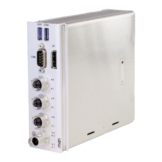
duagon MC50M User Manual (85 pages)
DIN-Rail Computer with Intel Atom Processor for Rolling Stock
Brand:
duagon
| Category:
Desktop
| Size: 5 MB
Table of Contents
Table of Contents
2
Contents
2
About this Document
6
Product Safety
10
Product Compliance
11
Disclaimer
12
Contacts
13
Product Overview
14
Product Description
14
Product Architecture
15
Interfaces
15
Figure 1. Front Interfaces
15
Functions
16
Figure 2. Functional Diagram
16
Technical Data
17
Cooling Concept
21
Product Identification
21
Figure 3. Sides Needed for Cooling (Exemplary System)
21
Identification of DIN-Rail Systems
22
Figure 4. Product Label
22
Figure 5. DIN-Rail System Label
22
Figure 6. Position of DIN-Rail System Label
22
Figure 7. Position of DIN-Rail Product Label (Back View)
23
Getting Started
24
Unpacking the MC50M
24
Configuring the Hardware
25
Installing In-System Devices
25
Mounting the MC50M
26
Safety Instructions for Mounting
26
Mounting the System on a DIN Rail
27
Figure 8. Mounting Terminal Blocks (Exemplary System)
28
Connecting and Starting
29
Safety Instructions for Connection
29
Connecting an Earthing Cable
29
Connecting Peripherals
30
Connecting the Power Supply
31
Figure 9. Power Configuration and Coding Labeling
31
Starting up the System
32
Figure 10. Connecting the Power Supply to a MP1/MC50M Combination
32
Configuring the UEFI Firmware for PXE Boot
33
Installing Operating System Software
33
Using the MC50M under Linux
34
Linux Support for Individual Functions
34
Yocto Linux Board Support Package (BSP)
35
Accessing Smbus/I2C Devices Using Standard Linux I2C Tools
35
Triggering the BMC Watchdog Directly Via CPU GPIO
35
Managing RTC Time Adjustments
36
Configuring the Serial Interfaces
36
Table 1. Linux Ttyfx to Front Interface Assignment
40
Accessing User Leds
43
Using the MC50M under Windows
44
Windows Support for Individual Functions
44
Managing RTC Time Adjustments
45
Configuring the Serial Interfaces
45
Functional Description
46
Power Supply
46
Pin Assignment for Product Versions 06Mc50Mxx
46
Pin Assignment for Prototype Versions 06Mc50Mpxx
46
Table 2. Connector Types - Power Supply (5-Pin M12)
46
Table 3. Pin Assignment - Power Supply (5-Pin M12 A-Coded) for 06Mc50Mxx
46
Table 4. Pin Assignment - Power Supply (5-Pin M12 A-Coded) for 06Mc50Mpxx
46
Ignition
47
Table 5. Signal Mnemonics - Power Supply
47
Figure 11. Ignition Behavior
48
Inrush Current
49
Power Cable
49
Figure 12. Ignition and Shut-Down Delay Watchdog State Diagram
49
Table 6. Inrush Current Measurements on PWR_IN
49
Cpu
50
Processor Core
50
Thermal Considerations
50
Trusted Platform Module (TPM)
50
Supervision and Management
50
Watchdog
50
Temperature Measurement
51
Event Logging
51
Status Leds
51
Table 7. General Status Leds at Front Panel
51
Table 8. CPU Status LED at Front Panel
52
Table 9. Error Codes Signaled Via Status LED Flashes
52
Real-Time Clock (RTC)
53
Software Support
53
Memory
54
System RAM
54
Boot Flash
54
Mass Storage
54
Emmc
54
SSD M.2 Slot (Nvme)
54
Isolation Voltages
55
Table 10. Isolation Voltages
55
Video (Service)
56
Front Connection
56
Table 11. Connector Types - Displayport
56
Table 12. Pin Assignment - Displayport
56
Table 13. Signal Mnemonics - Displayport
56
Front Interface Adapters
57
Displayport to Displayport Cable
57
USB (Service)
58
Front Connection
58
Table 14. Connector Types - USB 3.0
58
Table 15. Pin Assignment - USB 3.0
58
Table 16. Signal Mnemonics - USB 3.0
58
Ethernet
59
Front Connection
59
M12 to RJ45 Adapter Cable
59
Table 17. Connector Types - Ethernet (8-Pin M12 X-Coded)
59
Table 18. Pin Assignment - Ethernet (8-Pin M12 X-Coded)
59
Table 19. Signal Mnemonics - Ethernet
59
Ethernet MAC Addresses
60
Ethernet Status Leds
60
Table 20. Ethernet MAC Addresses
60
Table 21. Ethernet Status Leds
60
Rs232/Rs422/Rs485
61
Table 22. Connector Types - RS232/RS422/RS485 (9-Pin D-Sub)
61
Table 23. Pin Assignment - RS232/RS422/RS485 (9-Pin D-Sub)
61
Table 24. Signal Mnemonics - RS232
61
Table 25. Signal Mnemonics - RS422/RS485
61
UEFI Firmware
62
Accessing the Firmware
62
Setup Menus
62
Setup Modes
62
Main Menu
63
MEN Menu
64
Table 26. UEFI Firmware: MEN Menu
65
Table 27. UEFI Firmware: Sub-Menu BMC Settings
65
Advanced Menu
66
Table 28. UEFI Firmware: Sub-Menu Network Settings
66
Table 29. UEFI Firmware: Sub-Menu Memory Settings
66
Table 30. UEFI Firmware: Sub-Menu SATA Settings
66
Table 31. UEFI Firmware: Sub-Menu USB Settings
66
Chipset Menu
68
Security Menu
69
Table 32. UEFI Firmware: Setting Passwords
69
Table 33. UEFI Firmware: Security Modes
70
Boot Menu
71
Save & Exit Menu
72
Hardware/Software Interface
73
Smbus/I2C Devices
73
Table 34. Smbus/I2C Devices
73
Figure 13. System Positions Within a Modular DIN-Rail System
74
Table 35. CPU Module User LED and Ignition Watchdog Register Mapping
74
CPU Module User LED and Ignition Watchdog
75
50155 Documentation Compliance Overview
77
Table 39. Compliance with en 50155, Chapter 12.3 Datasheet
77
Compliance with en 50155, Chapter 12.5 Equipment Integration/Installation
84
Documentation
84
Advertisement
Advertisement
Related Products
duagon Categories
Desktop
More duagon Manuals
Login
Sign In
OR
Sign in with Facebook
Sign in with Google
Upload manual
Upload from disk
Upload from URL