
Summary of Contents for duagon MC50M
- Page 1 20MC50M00 E5 2020-10-20 MC50M DIN-Rail Computer with Intel Atom Processor for Rolling Stock Embedded System for IoT, Security and Predictive Maintenance User Manual...
-
Page 2: Table Of Contents
Using the MC50M under Windows........44... - Page 3 Contents 3.1.2 Pin Assignment for Prototype Versions 06MC50MPxx..46 3.1.3 Ignition..........47 3.1.4 Inrush Current .
- Page 4 Power configuration and coding labeling ......31 Figure 10. Connecting the power supply to a MP1/MC50M combination ... . 32 Figure 11.
- Page 5 Contents Tables Table 1. Linux ttyFx to front interface assignment ......40 Table 2.
-
Page 6: About This Document
- Electronic equipment) from the following chapters in the standard, as far as applicable: 12.3 Datasheet 12.4 User manual 12.5 Equipment integration/installation documentation MC50M product page with up-to-date information and downloads: www.duagon.com/products/mc50m/ 20MC50M00 E5 2020-10-20 ... - Page 7 Date First issue 2018-12-20 Updated chapter 2019-06-11 Power Supply Ignition Typical Application of the MC50M Connecting the Power Supply Added chapter EN 50155 Documentation Compliance Overview Using the MC50M under Windows Configuring the Serial Interfaces ...
- Page 8 SMBus/I2C Devices Updated figure Front interfaces Updated chapter Technical Data Cooling Concept Mounting the MC50M on a DIN Rail Connecting the Power Supply Ignition Inrush Current Real-Time Clock (RTC) Updated table Connector types –...
- Page 9 About this Document Conventions Indicates important information or warnings concerning situations which could result in personal injury, or damage or destruction of the component. Indicates important information concerning electrostatic discharge which could result in damage or destruction of the component. Indicates important information or warnings concerning proper functionality of the product described in this document.
-
Page 10: Product Safety
Technical Data. Use cases in environments exceeding the specifications in the applicable standards and the Technical Data have to be agreed upon between duagon and the customer. The product is not suitable for use in areas where children might be present. -
Page 11: Product Compliance
If the product delivered was certified by duagon and is modified by the customer, e.g., by installing an additional hardware component, the certification achieved by duagon becomes invalid and may have to be repeated for the new product configuration. -
Page 12: Disclaimer
In no case is duagon liable for the correct function of the technical installation where duagon products are a part of. -
Page 13: Contacts
860 Penllyn Blue Bell Pike Jinjiang Xiangyang Tower Blue Bell, PA 19422 200040 Shanghai Phone +1 215 542 9575 Phone +86 159 0077 2985 sales-usa@duagon.com sales-chn@duagon.com www.duagon.com www.duagon.com Copyright © 2020 duagon Germany GmbH. All rights reserved. 20MC50M00 E5 2020-10-20 ... -
Page 14: Product Overview
CCTV or ticketing system, or to act as a diagnostics server. Modular System for Easy Configuration The MC50M can be a stand-alone product, but due to the modular concept it offers flexible built-to-order configurations. The box can be easily combined with prefabricated extension modules, providing additional features and short delivery times. -
Page 15: Product Architecture
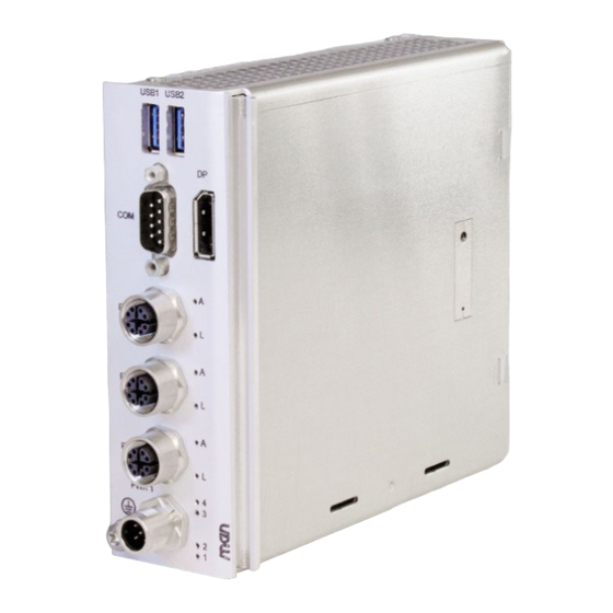
Product Overview Product Architecture 1.2.1 Interfaces Figure 1. Front interfaces USB 3.0 USB1 USB2 RS232/ DisplayPort RS422/RS485 Status LEDs ETH3 (Ethernet) ETH2 Gigabit ETH1 Ethernet Status LEDs PWR1 (Power, BMC) Power Input User LEDs Earthing Screw 20MC50M00 E5 2020-10-20 ... -
Page 16: Functions
Product Overview 1.2.2 Functions Figure 2. Functional diagram Gb Ethernet PCIe x1 Controller ECC DDR3 SDRAM Gb Ethernet PCIe x1 Controller Gb Ethernet eMMC USB 3.0 M.2 NVMe Intel Atom Slot USB 3.0 E3900 Series DisplayPort 1.2a PCIe x1 SATA (6 Gb) 10 LEDs SATA (6 Gb) RS232... -
Page 17: Technical Data
Product Overview Technical Data The following CPU types are supported: Intel Atom x5-E3930, 2 cores, 2 threads, 1.3 GHz, 1.8 GHz Turbo Boost, 6.5 W, 2 MB cache Intel Atom x7-E3950, 4 cores, 4 threads, 1.6 GHz, 2.0 GHz Turbo Boost, 12 W, 2 MB cache Memory System RAM... - Page 18 Product Overview Supervision and Control Board management controller Temperature measurement Watchdog timer Real-time clock, buffered by supercapacitor (5 days) Electrical Specifications Supply voltage 24 V DC nom. 48 V DC nom. Power consumption: 10 to 15 W typ. (depending on CPU type and CPU load), ...
- Page 19 Product Overview EMC emission EN 50121-3-2:2016 Regelung Nr. EMV 06 :2014-07-29, Anhang E: Messung an Geräten EMC immunity: EN 50121-3-2:2016 Protective coatings: EN 50155:2017, class PC2 (Any PCB protected on both sides) Useful life: 20 years (EN 50155:2017, class L4) ...
- Page 20 Apollo Lake platform are also available. Yocto BSP Driver support Tool support Tested with: Yocto BSP (Sumo 2.5, Linux kernel 4.15), Lubuntu 18.04 X LTS Chapter 2.6 Using the MC50M under Linux on page Windows Windows 10 IoT Enterprise 64-bit Driver support Tool support Chapter 2.7 Using the MC50M under Windows on page...
-
Page 21: Cooling Concept
Product Identification The documentation may describe several different models and design revisions of the MC50M. You can find the article number, design revision and serial number on either the product label or the system label. Article number: Indicates the product family and model. This is also the main ... -
Page 22: Identification Of Din-Rail Systems
Product Overview Figure 4. Product label Article No.: 01AXXX-00 Complete article number Serial No.: 000001 Rev.: 00.00.00 Serial number Revision number Figure 5. DIN-Rail system label Article No.: 01AXXX-00 Complete article number Serial No.: 000001 Serial number Rev.: 00.00.00 Revision number Identification of DIN-Rail Systems On a DIN-Rail system you can find the system label on the left side panel of the system housing. -
Page 23: Figure 7. Position Of Din-Rail Product Label (Back View)
Product Overview Figure 7. Position of DIN-Rail product label (back view) 20MC50M00 E5 2020-10-20 ... -
Page 24: Getting Started
Getting Started Getting Started Unpacking the MC50M After unpacking, check whether there are any transport or other damages on the system. If one of the following situations arises, have the equipment checked by service personnel: The power cable or plug is damaged. -
Page 25: Configuring The Hardware
See the duagon website for ordering information: www.duagon.com/products/mc50m/#ord Opening the MC50M and installing optional components may lead to a loss of the certification and therefore make the declaration of conformity invalid. Please order a pre-configured MC50M at duagon! 20MC50M00 E5 2020-10-20 ... -
Page 26: Mounting The Mc50M
Getting Started Mounting the MC50M 2.3.1 Safety Instructions for Mounting Risk of Damages or Injuries Make sure that the cabinet or the wall where you want to install the system supports the weight of the system. Risk of Fire Through Overheating Make sure that the equipment does not overheat. -
Page 27: Mounting The System On A Din Rail
Getting Started 2.3.2 Mounting the System on a DIN Rail The back wall of the system includes the retaining clip and guidance mechanics needed for mounting on a 35 mm top hat DIN rail (depth: 7.5 mm or 15 mm). The DIN rail must be mounted horizontally to ensure optimized convection cooling. -
Page 28: Figure 8. Mounting Terminal Blocks (Exemplary System)
Getting Started Make sure to mount DIN rail terminal blocks on both sides of the system after having mounted all components of the system. Figure 8. Mounting terminal blocks (exemplary system) Terminal block DIN rail 20MC50M00 E5 2020-10-20 ... -
Page 29: Connecting And Starting
The MC50M features an earthing connection. When using an MP1/MC50M combination, make sure to connect the earthing cable to the earthing screw on the MP1, not on the MC50M. Connect the earthing cable before making any other connections! ... -
Page 30: Connecting Peripherals
Connect a USB keyboard and mouse to the USB connectors at the front panel. » Connect a flat-panel display to a DisplayPort connector at the front panel of the MC50M. For the maximum resolution see Chapter Technical Data. Check the display specifications for recommended settings. »... -
Page 31: Connecting The Power Supply
When using an MP1/MC50M combination, connect the power supply and ignition input to the power inlet connector PWR2 on the MP1. When using an MP1/MC50M combination, do not remove the protective cover on the MC50M. Connecting the power supply to MC50M and MP1 simultaneously may ... -
Page 32: Starting Up The System
Table 4, Pin assignment - power supply (5-pin M12 A-coded) for 06MC50MPxx on page The following shows some typical configuration example of the MC50M. As the product concept is very flexible, other configurations including ME modules are also possible. Figure 10. -
Page 33: Configuring The Uefi Firmware For Pxe Boot
Getting Started 2.4.6 Configuring the UEFI Firmware for PXE Boot To enable PXE booting of the MC50M, configure the UEFI firmware as follows: For UEFI mode: Menu MEN: Setup Mode [Extended] Menu Advanced: Network Stack Configuration > Network Stack [Enabled] > IPV4... -
Page 34: Using The Mc50M Under Linux
Getting Started Using the MC50M under Linux 2.6.1 Linux Support for Individual Functions Notes: Functions have been tested with the mentioned software. 2.6.1.1 Board Management Controller BMC device on SMBus Supported by: Standard Linux I2C tools 2.6.1.2 Real-Time Clock (RTC) System RTC (ERTC) ... -
Page 35: Yocto Linux Board Support Package (Bsp)
2.6.2 Yocto Linux Board Support Package (BSP) duagon offers a Linux BSP supporting the MC50M. The BSP is intended to provide a quick start with the product in a Linux environment. It allows easy creation of boot media for first tests. It may not include support for every possible function, e.g., for licensing reasons. -
Page 36: Managing Rtc Time Adjustments
2.6.6 Configuring the Serial Interfaces The ASIX AX99100 UART controller on MC50M needs a special software driver to make the interfaces usable under Linux. If you use the Yocto BSP, you do not need to install the software driver; a ... - Page 37 Every physical interface corresponds to one "Port", resulting in one ttyFx device. //Port 1 [...] » Enter the following configuration for MC50M in structure uart_99100_contxt: The following code is specific to MC50M. Do not change these settings. Be aware that you do any changes at your own risk!
- Page 38 Getting Started static struct uart_99100_contxt uart_99100_contxts[] = { //Port 0 .rx_dma_en= 0, .tx_dma_en= 0, .uart_mode= AX99100_RS232_MODE, .en_flow_control= 0, .flow_ctrl_type = AX99100_RTS_CTS_HW_FLOWCONTROL, .rxfifotrigger= 64, .txfifotrigger= 64, .x_on = SERIAL_DEF_XON, .x_off= SERIAL_DEF_XOFF, .ltc2872_te485 = 0, .ltc2872_dz = 0, .ltc2872_lb = 0, .ltc2872_fen = 0, .pci_config_l0s= 0, .pci_config_l1 = 0, //Port 1...
- Page 39 Getting Started Include the path to the header file in the driver’s Makefile. nano Makefile ccflags-y +=-I/usr/lib/gcc/x86_64-pc-linux-gnu/7.3.0/include Run make clean: make clean Run make again: make » Install the serial driver module: make install You should now be able to use the serial ports as shown in the following table. 20MC50M00 E5 2020-10-20 ...
-
Page 40: Table 1. Linux Ttyfx To Front Interface Assignment
COM2 COM2 COM2 ETH3 yF11/ yF12 yF3/ yF4 yF7/ yF8 ETH2 COM1 COM1 COM1 ETH1 yF10 PWR1 MC50M/MC50I ttyF0 RS232 ttyF1 RS422/RS485 ME3 – first instance in system ttyF2 COM1 RS232 ttyF3 COM2 RS232 ttyF4 COM2 RS422/RS485 ttyF5... - Page 41 Getting Started 2.6.6.1 Using Interfaces in RS485 Half-Duplex Mode To use an RS422/RS485 interface in RS485 half-duplex mode, the control signals of the corresponding UART (RTS) must be used internally. Adapting the Driver Setting » Reconfigure the corresponding RS422/RS485 interface port from RS422 to RS232 mode in file ax99100_sp.c, structure uart_99100_contxt: .uart_mode= AX99100_RS232_MODE, »...
- Page 42 Getting Started 2.6.6.2 Configuring Console Redirection and Early-Console Functionality The following describes configuration in Ubuntu. Note: Replace ttyFx by the actual port designation in all examples. Console Redirection » Create a getty service for your console: nano /lib/systemd/system/serial-getty@.service Change the following line ExecStart=-/sbin/agetty --keep-baud 115200,38400,9600 %I $TERM to this setting: ExecStart=-/sbin/agetty 115200 %I $TERM...
-
Page 43: Accessing User Leds
Use the 7-bit SMB/I2C address to access a register. » Find out the number of the SMBus where the user LED register is located on MC50M. » If you are unfamiliar with the standard Linux tools, please read the related applica- tion note. -
Page 44: Using The Mc50M Under Windows
Functions have been tested with the mentioned software. 2.7.1.1 Board Management Controller BMC device on SMBus Supported by: duagon xm01bc_1 tool (included in 13Y021-70 Windows ERTC/ SMB Support Package) 2.7.1.2 Real-Time Clock (RTC) External RTC Supported by: duagon 13Y021-70 Windows ERTC/SMB Support Package 2.7.1.3... -
Page 45: Managing Rtc Time Adjustments
The ERTC time will not be updated and is out of date. During the next system boot, the OS would use the outdated time. duagon provides a dedicated ERTC driver to manage system time adjustments. See the duagon website for user manual Windows ERTC/SMB Support Package. -
Page 46: Functional Description
Functional Description Functional Description Power Supply The MC50M is supplied via a power inlet connector at the front panel. Chapter Connecting the Power Supply for a detailed description. Table 2. Connector types – power supply (5-pin M12) Connector Type On MC50M... -
Page 47: Ignition
3.1.3 Ignition You can use the ignition pin to control the start-up and shut-down of the MC50M without having to disconnect the power supply. Only for prototype version 06MC50MPxx! If you use the MC50M without PSU module MP1, bridge pins 3 and 4 (GND pins) of the power input connector externally to make the ignition work properly. -
Page 48: Figure 11. Ignition Behavior
The ignition pin can also be permanently connected to the power input pin. In this case the MC50M will start up as soon as the supply voltage is con- nected and switch off as soon as the supply voltage is disconnected without a delay for shutting down the operating system. -
Page 49: Inrush Current
WDOG:ON Power:ON WDOG:RESET 3.1.4 Inrush Current To prevent damages to the MC50M due to exceeding inrush current, take the measured inrush current values into account when designing your circuit protection. Table 6. Inrush current measurements on PWR_IN Inrush Current Input Voltage Inrush Energy I²t... -
Page 50: Cpu
Trusted Platform Module (TPM) A trusted platform module for authenticating the hardware to ensure platform integrity is available on the MC50M. The TPM module is compliant to the TPM v2.0 specification. Supervision and Management The MC50M provides an intelligent board management controller (BMC) with the... -
Page 51: Temperature Measurement
The following units can generate events in the log: Application software running on MC50M The event time stamp is derived from the BMC’s operating hours counter. The length of power cuts is not visible in the event log. -
Page 52: Table 8. Cpu Status Led At Front Panel
Indicates MC50M status messages: On: MC50M firmware starting Off: MC50M is switched off Blinking: MC50M is in stand-by (S3) status Blinking with n flashes: Error code During normal operation the LED can be switched on and off using software. -
Page 53: Real-Time Clock (Rtc)
Functional Description Real-Time Clock (RTC) The MC50M includes a real-time clock connected to the processor as the system RTC (ERTC) RX-8571LC. The RTC has an accuracy of approximately 1.7 seconds/day (11 minutes/year) at 25°C. The real-time clock device is connected to the CPU via SMBus. -
Page 54: Memory
The boot Flash memory contains the UEFI firmware. Mass Storage 3.7.1 eMMC The MC50M comes with an eMMC multimedia device already soldered on the board. Supported memory size: 64 GB max. See the duagon website for available standard configurations: www.duagon.com/products/mc50m/#ord... -
Page 55: Isolation Voltages
500 V AC 500 V AC 500 V AC 500 V AC When using MC50M in combination with MP1, isolation between Power IN, GND and earthing/shield is provided. See also Chapter 2.4.4.1 Connecting the Power Supply to an MP1/MC50M Combination on page... -
Page 56: Video (Service)
Service interfaces may only be used with a maximum cable length of 3 m for wayside installations 10 meters or less away from the track. Table 11. Connector types – DisplayPort Connector Type On MC50M 20-pin DisplayPort receptacle Mating 20-pin DisplayPort plug Table 12. Pin assignment – DisplayPort... -
Page 57: Front Interface Adapters
DisplayPort adapter is applicable. Note: Passive DisplayPort adapters are only applicable for up to two monitors. 3.9.3 DisplayPort to DisplayPort Cable duagon offers a starter kit including a DisplayPort to DisplayPort cable. See the duagon website for ordering information: www.duagon.com/products/mc50m/#ord 20MC50M00 E5 2020-10-20 ... -
Page 58: Usb (Service)
10 meters or less away from the track. Table 14. Connector types – USB 3.0 Connector Type On MC50M 9-pin USB 3.0 Standard-A receptacle according to Universal Serial Bus Specification Mating 9-pin USB 3.0 Standard-A plug according to Universal Serial Bus Specification Table 15. -
Page 59: Ethernet
Transmit data lines for 10/100BASE-T 3.11.2 M12 to RJ45 Adapter Cable duagon offers a starter kit including an M12 to RJ45 adapter for making the Ethernet interfaces available on standard Ethernet connectors. See the duagon website for ordering information: www.duagon.com/products/mc50m/#ord... -
Page 60: Ethernet Mac Addresses
Upper front 0x 00 C0 3A EE 10 00 "00 C0 3A" is the duagon vendor code. The last six digits form the unique MAC address for each board. The last three digits correspond to the serial number of each MC50M: Serial number 42 (ETH1): 0x0000 + 0x002A = 0x002A. -
Page 61: Rs232/Rs422/Rs485
Functional Description 3.12 RS232/RS422/RS485 Table 22. Connector types – RS232/RS422/RS485 (9-pin D-Sub) Connector Type On MC50M 9-pin D-Sub plug e.g., Assmann A-D-S-09-A/KG-LP Mating 9-pin D-Sub receptacle e.g., Assmann A-D-F-09-A/KG-LP Tightening torque: max. 0.6 Nm Table 23. Pin assignment – RS232/RS422/RS485 (9-pin D-Sub) -
Page 62: Uefi Firmware
UEFI Firmware UEFI Firmware The MC50M comes with UEFI-based Aptio firmware from AMI. For more user- friendliness it has been modified by duagon. You can enter the firmware settings using a setup menu. Accessing the Firmware » Power up the system. -
Page 63: Main Menu
UEFI Firmware 4.3.1 Main Menu In the Main menu you can look up system parameters and set system language, date and time. Aptio Setup Utility - Copyright (C) 2017 American Megatrends, Inc. Main Advanced Chipset Security Boot Save & Exit /----------------------------------------------------+-------------------------\ BIOS Information ^|Choose the system... -
Page 64: Men Menu
UEFI Firmware 4.3.2 MEN Menu The MEN menu has been adapted in order to simplify access to important functions. You can find information regarding board name, board revision and serial number as well as several sub-menus. Aptio Setup Utility - Copyright (C) 2017 American Megatrends, Inc. Main Advanced Chipset... -
Page 65: Table 26. Uefi Firmware: Men Menu
UEFI Firmware 4.3.2.1 MEN Menu – Sub-Functions Table 26. UEFI firmware: MEN Menu Function Options Setup Mode Standard Extended 4.3.2.2 MEN Menu – Sub-Menu BMC Settings In the BMC Settings sub-menu you can find board information that is read out via the Board Management Controller (BMC), as well as the following sub-functions: Table 27. -
Page 66: Advanced Menu
UEFI Firmware 4.3.2.3 MEN Menu – Sub-Menu Network Settings Table 28. UEFI firmware: Sub-Menu Network Settings Sub-menu Function Options MEN Network Settings CM50 Gigabit Ethernet Enabled Disabled PXE Boot for CM50 ETH Enabled Disabled PXE Boot for additional GbE Enabled Disabled 4.3.2.4 MEN Menu –... - Page 67 UEFI Firmware Aptio Setup Utility - Copyright (C) 2017 American Megatrends, Inc. Main Advanced Chipset Security Boot Save & Exit /----------------------------------------------------+-------------------------\ |> Serial Port Console Redirection |> CPU Configuration |CPU Configuration |> Network Stack Configuration |Parameters |> CSM Configuration |> SDIO Configuration |>...
-
Page 68: Chipset Menu
UEFI Firmware 4.3.4 Chipset Menu Most of the functions in this menu normally do not have to be changed during operation. If necessary, by entering the configuration menu you can change the settings regarding, e.g, HD Audio or PCI Express. Aptio Setup Utility - Copyright (C) 2017 American Megatrends, Inc. -
Page 69: Security Menu
UEFI Firmware 4.3.5 Security Menu In the Security menu you can enter passwords for user profiles User and Administrator. Aptio Setup Utility - Copyright (C) 2017 American Megatrends, Inc. Main Advanced Chipset Security Boot Save & Exit /----------------------------------------------------+-------------------------\ Password Description |Set Setup Administrator |Password If ONLY the Administrator's password is set,... -
Page 70: Table 33. Uefi Firmware: Security Modes
UEFI Firmware Table 33. UEFI firmware: Security modes Setting Description No password is set Booting the system and opening the UEFI setup is not protected. Only administrator password Booting the system is not protected. is set For opening the UEFI setup, the administrator ... -
Page 71: Boot Menu
UEFI Firmware 4.3.6 Boot Menu In the Boot menu you can make settings regarding boot behavior and boot order. Aptio Setup Utility - Copyright (C) 2017 American Megatrends, Inc. Main Advanced Chipset Security Boot Save & Exit /----------------------------------------------------+-------------------------\ Boot Configuration |Number of seconds to Setup Prompt Timeout |wait for setup... -
Page 72: Save & Exit Menu
UEFI Firmware 4.3.7 Save & Exit Menu In the Save & Exit menu you can set how to handle changes made within the setup and exit the setup. Using the Boot Override function you can boot from a medium different from the one set in the boot order. -
Page 73: Hardware/Software Interface
SMBus/I2C Devices Depending on the position of the MC50M within the modular DIN-Rail system, the SMBus address may differ. The following table gives an overview of the SMBus devices within a complete DIN-Rail system, not only for an individual module. -
Page 74: Figure 13. System Positions Within A Modular Din-Rail System
Hardware/Software Interface Figure 13. System positions within a modular DIN-Rail system ME module ME module ME module ME module ME module module including carrier Note on 8-Bit/7-Bit Addressing 8-bit addressing is compliant to the Windows nomenclature. The last bit, which is used as the read/write bit, is added to the address (0 = write, 1 = read). -
Page 75: Cpu Module User Led And Ignition Watchdog
Hardware/Software Interface Table 36. CPU module user LED and ignition watchdog data register (read) (offset 0x00) WDOG Name Reserved USR_LED4 USR_LED3 Reserved Access Reset Bit Field Description WDOG_EN Reset power supply watchdog (ignition) 0: Watchdog reset 1: Normal operation ... - Page 76 Hardware/Software Interface Bit Field Description WDOG_EN Enable or disable power supply watchdog control 0: Enable watchdog control 1: Disable watchdog control USR_LED[4:3] Enable or disable user LED function 0: Enable LED function 1: Disable LED function (LED appears dimmed) ...
-
Page 77: 50155 Documentation Compliance Overview
Different versions of the product, as far as orderable, have a unique article number. A list of standard versions is available on the MC50M product web page under "Ordering Information". www.duagon.com/products/mc50m/#ord b) table of contents Chapter Contents... - Page 78 5) interruptions on power supply Chapter Product Overview > Technical Data voltage Class > Product Compliance: Rail - Rolling Stock 6) supply change-over class (if Not applicable for MC50M appropriate) 7) earth potential reference Chapter Product Overview > Technical Data > Interfaces > Power...
- Page 79 (if any) regarding hazardous materials. duagon can provide a materials report for MC50M on request. 12) RoHS, compliance if applicable Chapter Product Compliance 13) REACH compliance...
- Page 80 The MC50M is repairable. equipment or parts of the equipment (if any) 3) identification of the LRU parts of The MC50M does not include LRU parts. the electronic equipment 4) MTTR (if any) No definite value can be given, as the MTTR depends on the use case and the product version.
- Page 81 EN 50155 Documentation Compliance Overview Requirement Compliance i) functional description and interfaces 1) functional block diagram, including Chapter Product Overview > Product hardware and software Architecture > Functions 2) central processing unit and Chapter Functional Description > CPU peripherals (if relevant) 3) memory (if relevant) Chapter Functional Description >...
- Page 82 3) reference of Application Notes (if Information is provided as far as any) appropriate in the relevant chapter. A complete list of documentation is available on the MC50M product web page under "Documentation". www.duagon.com/products/mc50m/#doc 4) reference of Equipment Not relevant...
- Page 83 Chapter Getting Started provides upload on the electronic equipment information on supported software. (if any) A concrete list of software is available on the MC50M product web page under "Software". www.duagon.com/products/mc50m/ #downl m) datasheet document history with Chapter About this Document...
-
Page 84: Compliance With En 50155, Chapter 12.5 Equipment Integration/Installation
Earth terminals location Chapter Product Overview > External Interfaces Chapter Getting Started > Connecting an Earthing Cable Shielding requirements for input or The MC50M requires shielded cables for output wired signals the following interfaces: Ethernet Serial (RS232/RS422/RS485) ... - Page 85 EN 50155 Documentation Compliance Overview Requirement Compliance Interconnection diagrams and charts Chapter Product Overview > Product Architecture > Possible Applications and Configurations Hardware and software Interface Chapter Functional Description information See the respective function chapter. Chapter Hardware/Software Interface 20MC50M00 E5 2020-10-20 ...
Need help?
Do you have a question about the MC50M and is the answer not in the manual?
Questions and answers