Sign In
Upload
Manuals
Brands
dtec Manuals
Measuring Instruments
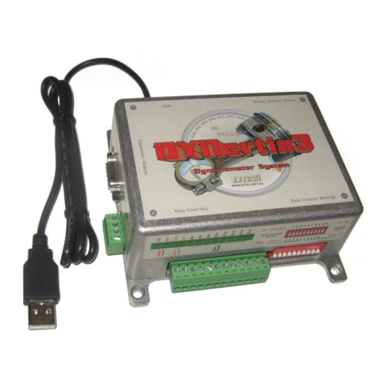
DYNertia3
dtec DYNertia3 Manuals
Manuals and User Guides for dtec DYNertia3. We have
2
dtec DYNertia3 manuals available for free PDF download: User Manual, Quick Start Manual
dtec DYNertia3 User Manual (174 pages)
Brand:
dtec
| Category:
Measuring Instruments
| Size: 17 MB
Table of Contents
Table of Contents
3
Chapter 1: Introduction
10
Introduction
11
Features
12
Overview
12
Analysing Test Results
12
Data Acquisition
13
File Management
14
Printing
14
Additional Functions
14
Load Control Options (EC and PC Units)
15
Chapter 2: Hardware Installation
16
Hardware Mounting
17
Mounting the Dynertia3 Sensor and Magnet
17
Alternate Sensors to the Supplied One
18
Mounting the Electronic Control Unit
19
Hardware Wiring
20
Power Supply Connection
20
Example of Typical Wiring (Additional Devices Shown)
21
Linking' Hardware to PC
22
Chapter 3: 'Brake' Style Dyno Setup
23
Brake (Absorber) Style Dyno Setup
24
Basic Concept
24
Variations
25
Types of Testing Used with Brake (Retarder/Absorber) Style Dyno's
25
Load Cell Calibration and Wiring for Brake Type
25
Chapter 4: 'Setup' Menu Options
26
Hardware- Setup Menu
27
Brake / Inertia Button
27
Chassis / Engine Button
27
Inertia Mass Constants
27
Roller Circumference
27
Tire Circumference
27
Mass RPM Limit
27
Sensor/Mass Ratio
28
Pulse Generator
28
Tacho / Speedometer
28
OBDII Adapter Input for Engine RPM and Vehicle Speed
28
RPM Adapter Input for Engine RPM
28
Brake Inertia Correction (Only in 'BRAKE' Mode)
29
After Run Auto Braking/Vehicle Loading
29
Hardware Connections
30
Circumference Calculator
30
Moment of Inertia Calculator
30
Software- Setup Menu
31
Graph Smoothness
31
Point by Point (Open Loop Brake Mode)
31
Inertia Mode Graph Smoothness
31
Passwords
31
Password (Program & Setup)
31
Lambda / AFR
31
Preferred Lambda/Afr Channel
31
Custom Fuel - Stoic/Afr and Name
31
Graph
32
Auto Display of Last Run
32
Graph Torque Traces
32
Graph Trace ID's
32
Auto Shift Traces Right
32
RPM / Speed Scales
32
Power / Torque Scales
32
Run
32
Run Screens - Chart Reorders
32
Run Duration
32
Display
33
Multiple Monitor Support
33
Hide Windows Desktop
33
Data Window Transparency
33
Screensaver
33
About
33
Display of System Details
33
System
34
End of each Run
34
DYNO Correction Systems
34
Run D3 Snapshot
34
Configuration Reset
34
General
35
Metric / Imperial
35
Media (Audio)
35
Remote 'Page Turner' Actions
35
Data Consistency
35
Point by Point (Brake Mode)
36
Ratios
37
Last Ratio Set
37
Low Speed / RPM Operation
37
Set Ratio- Change Increment
37
Run Comments
37
Comment Editing
37
Comments Added to each New Run
37
Company Name
37
Outputs
37
All Outputs (Dynertia3 and Accessories)
37
File Storage Paths (Icon)
38
Set Dynertia3 Base File Storage Path
38
User Details (Icon)
38
Set User Details
38
Archive Storage Paths (Icon)
39
Set Dynertia3 Archive Storage Path
39
Load Control- Setup Menu
39
Communications- Setup Menu
40
Interface Port no
40
Link Button
40
Manual Set Button
40
Dynertia3
40
Dynertia Sensor Test
40
Weather Watch
40
Update Interval
40
Load Controller
41
Torque Sensor
41
Obdii
41
Device Manager
41
Open Windows Device Manager
41
Prm/Speed Source
42
Sensor Configuration
42
Data Limits / Alarms
42
Losses Systems
42
Main Graph Trace Colour (Visible Only from 'Graph' Screen)
42
Grid
42
Operator
42
Printer
42
Chapter 5: RPM Input Options
43
Engine RPM, Purpose and Options
44
Why We May Need Engine RPM
44
Windows Used for RPM Setup (Referred to in this Chapter)
44
RPM Input Options (7 Available!)
45
RPM Adapter Input
47
Summary of Your RPM Options
49
General RPM Input Information
49
Chapter 6: Overview- 2 Main Windows
50
Two Main Dynertia3 Windows (DYNO / GRAPH)
51
DYNO Window
52
Record Settings
52
Minimum Run RPM
52
Maximum Run RPM
52
Current Ratio
52
Mode
53
Status
53
Dynertia3 Hardware Lamps (DYN)
53
Run Control
54
Start Run Button
54
Correction Factors
55
User Comments Field
55
Output Controls and Status
55
Dial Gauge Displays
56
Power & Torque Dials
56
Rpm/Speed Dial
56
Gauges Mode
56
Data Gauges on Button
56
Speed to RPM (Ratio Setting)
56
Strip Charts
56
Data Dial Gauges
56
GRAPH Window
57
Tool Bar Button Functions
57
Exit
57
Print
57
Rpm/Speed Mode
57
Graph/Dyno
57
Selecting Trace to Analyze
57
Selecting Trace to Display
57
Graph Controls
58
Data Displays
59
Run Time Gauges/Charts (Visible Only from 'DYNO' Window)
60
RPM and Speed Scales
60
Chapter 7: Weather Corrections
61
Correction Factors
62
Viewing Weather Data
63
Chapter 8: Loading/Viewing Files
64
Loading of Files into 'GRAPH' Window
65
Previewing (Dynertia3 File Explorer) and Selecting Files
65
Dynertia3 File Explorer
66
Creating / Deleting Folders for Tests
68
Reviewing Audio Files
69
Secondary GRAPH Window
70
Viewing Files ('GRAPH' Window)
71
Adjusting Graph Appearance
71
Zooming
71
Clear Graph Trims
71
Clear Graph
71
Trace Visibility
71
Grid
71
Chapter 9: Trim, Merge & Join Runs
72
Trim a Run
73
Merge Runs
74
Join Runs
75
Chapter 10: Test Notes- Add/Save
76
Adding Test Notes
77
User' Comments Field
77
Accessing User Comments
77
Templates
78
Saving Notes and Applying to Other Tests
78
Chapter 11: Printing & Exporting
79
Printing
80
General Printing
80
Print
80
Setup Printer
80
Offset Correction
80
Printing Main Graph Screens
81
Dyno Operator
81
Information for Printed Output
81
Print
81
Select Page
81
Customising Your Printout
82
User Details and Company Logo
82
Customer Disclaimer
82
Notes to Print
83
General Comments for Printing
83
Produce Comments on the Main Graph for Printing
83
Exporting Data
84
Select a Trace to Export
84
Chapter 12: Live Data Viewing
85
Gauge Screens
86
Observing the Engine Data
86
Observing the Data Channels
88
Display Current Afr/Lambda
89
Chapter 13: Analysing Data ('View' Menu)
90
Trace Info
91
Secondary Graph
91
Individual Trace Set
92
Compare
93
Torque Analysis
94
Losses
95
Lambda / AFR Deviation
96
Distance / Speed / Time / RPM Analysis
97
Slip / Tyre Growth
98
Run Duration Info
99
Point to Point Times
100
XY Graph
101
Run Data Vs Time
102
Chapter 14: Inputs- Using
103
Pin Allocations
104
General Input Notes
105
Important General Information
105
Wiring Inputs for Best Results
105
Connecting Sensors
106
General Sensor Connection (0-5V Input Shown)
106
Resistive Sensor Connection
107
Connection of Dtec's 'Thermo-Amp' Thermocouple Amplifier (for K-Type Sensors)
107
Air/Fuel Ratio Meter Connection (Dtec 'WB2' Unit as Example)
108
Connection of Load Cell for Brake (Absorber) Style Dyno's
108
RPM Adapter Input
109
General Notes on Wiring the RPM Adapter Input (Secondary Way of Measuring RPM)
109
Using a Dtec 'RPM Adapter' for the RPM Adapter Input
109
Basic Connections for a Dtec 'RPM Adapter' to Dynertia3'S RPM Adapter Input
110
Connections for a Dtec 'RPM Adapter' to Suit Spark Plug Wire Sensing
110
Connections for a Dtec 'RPM Adapter' to Suit Coil 'Switching' Signals
110
Connections for a Dtec 'RPM Adapter' to Suit Coil 'Drive' Signals
111
Connections for a Dtec 'RPM Adapter' to Suit 'VR' (Inductive) Sensors
111
Sensor Configuration
112
Configuring an Input Channel Using Pre-Settings
112
Creating Your Own Linear (2 Points, Straight Line) Sensor Calibrations
113
Naming and Calibrating of Lambda / AFR Meter Inputs
114
Creating Your Own Non-Linear Sensor Calibrations
114
Testing Sensor Configurations
116
Getting the Best Data
117
Channel Filtering
117
Reference Voltage Correction
117
Sensor Alarm Points
118
Sensor on / off (Recording)
118
Data Consistency
119
Chapter 15: Outputs- Using
120
Auxiliary Connections
121
Connecting Outputs if Required
121
Output Functions
121
Run' Output
121
User' Output
121
Brake' Output
122
Chapter 16: Load Controllers
123
Hardware Mounting & Basic Wiring
124
Mounting the Speed Sensor
124
Mounting Electrical Components
124
Eddy Current Load Controller Wiring
125
Eddy Controller Wiring (Basic- no Accessories)
125
Eddy Current Controller Wiring Harness Connections
126
PWM Current Load Controller Wiring
127
Wiring PWM Controller Wiring (Basic- no Accessories)
127
PWM Current Controller Wiring Harness Connections
128
Load Cell Connection
129
Wiring of the Load Cell (Including Pressure Sensor Style)
129
Load Cell Setup & Calibration
130
Sensor Calibration
130
Manual Sensor Calibration
132
Automatic Sensor Drift Cancellation
132
Brake 'Closed Loop' PID Tuning
133
Load Control System Commissioning
133
Load Unit- Current Limitation
133
Load Control Output
133
Throttle Servo Speed
133
Sudden Rpm/Speed Drop Warning
134
PID Test Settings
134
Setup Procedure
135
Proportional Value
135
Integral Value
135
Derivative Value
135
Upload Settings
136
Saving and Loading Configurations
136
Last Runs PID Power
136
PID Settings History
136
Over Temperature Load Thermostat
136
Closed Loop' Windows
137
Load Control Window
137
Manual Testing Load Control
137
Manual Load Control
137
Manual Target Fast Setting
137
Ramp Testing Load Control
138
Ramp Load Control
138
Ramp Mode Editor
138
Saving and Loading Timelines
138
Step Testing Load Control
139
Step Load Control
139
Step Mode Editor
139
Saving and Loading Timelines
139
User Testing Load Control
140
User Load Control
140
User Mode Editor
140
Saving and Loading Timelines
140
Run Options, Files and Information
141
Timeline Preview and Selection
141
Throttle Trims
141
Manual Min RPM
141
Manual Mode Load Response
142
Load Control Keyboard Steps
142
Run Min/Max
142
Auxiliary Outputs
142
Run Throttle
142
Record Run
142
Load Controller Auxiliary Options
143
Expansion Port Overview
143
Expansion Port Connection Details
143
Expansion Port Functions
144
Throttle Output
144
Throttle Input
144
Auxiliary Outputs 1 and 2
145
Over Temperature Alarm Input
145
Chapter 17: Losses Correction
146
Losses' System
147
What Are the Effects of Mechanical Losses
147
What Does Measured Mechanical Loss Correction Do
147
Are These "Losses" Worth Worrying about
147
Configuration Window
148
USER ESTIMATED Mechanical Loss Correction
150
MEASURED Mechanical Loss Correction
151
General Setup for DYNO Loss Testing
152
How Often Should I Run DYNO Losses Correction
152
Observing Effect of Losses Correction
153
Chapter 18: Maths Channels
154
Concept
155
Sample Expressions, Simple
157
Testing an Expression
157
Variables in Detail
157
Creating and Saving a Math's Expression
158
Applying an Expression to a Dyno File
158
Exception' Notifications
159
Chapter 19: 'Utilities' Menu
160
Send an Email
161
Lambda AFR Converter
161
RPM / Torque / Power Calculator
162
Metric / Imperial Convertor for Torque / Power
162
Display Current Weather Data
162
Display Current Afr/Lambda
163
Rpm/Speed Stability
163
Data Diagnostics
164
Chapter 20: Trouble Shooting & Faq's
165
Trouble Shooting- Common Issues
166
Frequently Asked Questions (Faq's)
169
Chapter 21: Specifications
170
Specifications
171
Notes
172
Chapter 22: Additions & Changes
173
Software V3.4.X Changes & Errata
174
Advertisement
dtec DYNertia3 Quick Start Manual (20 pages)
Brand:
dtec
| Category:
Measuring Instruments
| Size: 3 MB
Table of Contents
Table of Contents
3
Concept
4
Hardware Mounting & Basic Wiring for Initial Setup
4
Mounting the Dynertia3 Sensor and Magnet
4
Dynertia3 Control Unit Mounting
5
Basic Wiring
6
Linking' Hardware to PC
7
Two Main Dynertia3 Windows (DYNO / GRAPH)
8
Basic Hardware Settings
9
First Time Use, Hardware Setup
9
Basic Software Settings (Default)
10
Quick Test of Dyno Speed Sensor
10
Displaying Engine RPM (One Method)
11
Performing a Basic Inertia Test 'Run
12
You Are Now Ready to Perform a Test
12
Observing the Engine Data During a Test
13
Viewing/Loading of Runs ('Graph' Window)
14
Loading Test Runs into the Graph Window to View and Analyze
14
Finding Folders to View or to Save Tests into
15
Creating/Deleting New Folders to Save Tests into
15
Basic Analysis of Saved Data
16
Windows for Further Analysis of Saved Data
17
Shortcuts
18
Troubleshooting
19
Assessing Test Results- Poor Settings
19
Assessing Test Results- Signal Issues
20
Advertisement
Related Products
dtec Denta/Dentaplus
dtec Denta
dtec Dentaplus
dtec CONTROL V7E
dtec Categories
Measuring Instruments
Light Fixture
Security Sensors
More dtec Manuals
Login
Sign In
OR
Sign in with Facebook
Sign in with Google
Upload manual
Upload from disk
Upload from URL