Sign In
Upload
Manuals
Brands
Dreizler Manuals
Burner
marathon MC 1001
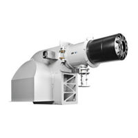
User Manuals: Dreizler marathon MC 1001 Gas Burner
Manuals and User Guides for Dreizler marathon MC 1001 Gas Burner. We have
1
Dreizler marathon MC 1001 Gas Burner manual available for free PDF download: Manual
Dreizler marathon MC 1001 Manual (184 pages)
Gas burners hightech low emission
Brand:
Dreizler
| Category:
Burner
| Size: 12 MB
Table of Contents
Table of Contents
3
1 Safety Instructions
10
2 CE Certification and Declaration of Conformity
12
3 Directive (EC) No. 1907/2006 / REACH Regulation
17
4 Burner Construction in Marathon® Gas Burners
18
The Mixing Manifold
18
The Marathon® Burner System
19
5 Burner Construction in Gas and Dual Fuel Burners Model Monobloc
20
Burner Construction Marathon® M 1001 - 5001.1 Monobloc
20
Burner Construction Marathon® M/MC 5001 and 10001 Monobloc
21
6 Burner Construction in Gas and Dual Fuel Burners Model Duobloc M/MC 10003
22
Burner Construction Marathon® Duobloc
22
7 Operations Manual for Marathon® Gas Burner
23
8 Commissioning Procedures for Marathon® Gas Burner
24
Prerequisites for First Commissioning
24
Preparation for First Commissioning
24
Commissioning
24
9 Settings for Marathon® Burner with Pneumatic Linkage
25
Description and Functionality of the Pneumatic Linkage
25
Presetting of the Motorised Air Damper (Pressure Side) for MAX Load
25
Presetting the Manual Damper for Maximum Load (Suction Side)
26
Setting Burner Load
27
Presetting of the Motorised Air Damper (Pressure Side) for MIN Load
28
Setting Minimal Burner Load
28
10 Gas/Air Ratio Control with Pneumatic Linkage
30
Description of Gas/Air Ratio Control
30
Functionality of Gas/Air Ratio Control
30
Instructions for the Configuration of the Gas/Air Ratio Control
31
11 Settings for Burner with Electronic Linkage
32
Presetting the Gas and Air Damper by Way of the Servomotor
32
Adjustment of the Operation Distance of the Speed Transmitter
32
Procedure
33
Setting the End Stops
33
Settings for the Potentiometer
33
Configuring the Frequency Converter
33
Configuration of the Burner Management System ETAMATIC OEM
33
Configuring the Load Point
33
Configuring the Combustion Manager Burnertronic BT 3Xx
34
Doweling of Servomotor and Oil Regulator in the Type BT 3Xx
34
Configuring the Gas/Oil Pressure Switch
35
Gas Pressure Switch MIN
35
Gas Pressure Switch MAX
35
Air Pressure Switch
35
Oil Pressure Switch MIN
35
Oil Pressure Switch MAX
35
12 Settings for Marathon® Burners with Mechanical Linkage
36
Preadjustment the Gas and Air Dampers for Small Loads (MIN)
36
Preadjustment the Gas and Air Dampers for Full Loads (MAX)
36
Basic Settings for Gas and Air Damper
37
First Start-Up of the Burner on the Boiler
38
Function Check of the Control Process Via Limiter Switch
38
Burner Start-Up in MIN Position
38
Burner Adjustments
39
Adjustment of Combustion Air in Position MIN (Small Load)
39
Fine Tuning the Gas and Air Volume
40
Setting Intermediate Positions
40
Effects on Gas to Air Ratio Based on Adjustments of the Swiveling Ranges J 1 and J 2
44
Setting the Ignition Phase
45
Final Check
46
13 Decommissioning a Marathon® Gas or Dual Fuel Burner
47
Procedure
47
14 The Air Damper
48
Technical Description
48
Air Damper Configuration
49
Air Damper - Burner Allocation
49
15 Configuration of the Ring Air Damper
50
Presetting the Ring Air Damper in Horizontal Position
50
Correction of the Air Distribution in Case of Uneven Flame
50
16 Servomotor Type SQN 7
51
Function
51
Preadjustment of the Servomotor SQN 7
51
Description of the Control Process in Burner Operation
52
Potentiometer for SQN 7
53
Retrofitting the Servomotor for Potentiometer Operation
53
17 Servomotor Type SQN 3
57
Function
57
Preadjustment of the Servomotor SQN 3
57
Description of the Control Process in Burner Operation
58
Potentiometer for Servomotor SQN 3
59
Retrofitting the Servomotor for Potentiometer Operation
59
18 Servomotor Type SQM 5
60
Function
60
Preadjustment of the Servomotor SQM 5
61
Description of the Control Process in Burner Operation
62
Rotational Direction Setting for Servomotor SQM 5
62
Connection Terminals for Servomotor SQM 5
63
Potentiometer for Servomotor SQM 54
63
Retrofitting the Servomotor for Potentiometer Operation
64
19 Ignition and Flame Monitoring of Gas Burners Marathon® M
65
Ignition of Gas Burners up to 7,5 MW with Torus Swirl Mixing
65
Configuration and Installation of Dual Ignition Electrodes
65
Configuration of the Dual Ignition Electrodes
65
Ignition Gas Burner and Gas Part of Dual Fuel Burner up to 7,5 MW
66
Ignition Without Pilot Burner
66
Ignition with Pilot Burner
67
Flame Detection
68
Configuration and Installation of Ionisation Electrodes
68
20 Oil Hoses - Operation, Storage and Replacement Intervals
71
Criteria for the Replacement
71
Storage Conditions
71
21 Ignition Gas Burner and Gas Part of Dual Fuel Burner
72
Ignition Without Pilot Burner
72
Ignition with Pilot Burner
73
22 Ignition Transformer
74
Ignition Transformer ZE 30 / 7.5 (Single Pole)
74
Description
74
Technical Data
74
Single-Pole Ignition
74
Ignition Transformer ZM 20 / 10 (2-Pole)
75
Description
75
Technical Data
75
2-Pole Ignition
75
Ignition Transformer Configuration
75
Gas Burner
75
Dual Fuel Burner
76
Ignition Transformer Configuration from Model M 5001 / MC 1501
76
23 Nozzle Assembly in Marathon® Gas Burners
77
Gas Burner with Torus Swirl Mixing and Burner Rings
77
Nozzle Assembly and Flame-Tube Assembly Gas-Standard
78
Nozzle Assembly and Flame-Tube Assembly Gas
79
24 Nozzle Bores in Gas Burners
80
25 Flame Tube Mounting Dimensions
82
26 Mounting the Burner Flange Seal
84
Mounting the Flat Sealing Tape PTFE between Burner Flange and Boiler Door
84
Reference Values for Tightening Torque
84
27 Mounting a Dismantling Tool on the Burner Head
86
Dismantling Tool for Monobloc Burner M/MC 10001
86
Setting of Height Adjustable Support of the Dismantling Tool
87
Assembly of the Flame Tube Ring Head Ø 500
87
Dismantling Tool for Duobloc Burner M/MC 10003
88
28 Transport Requirements
90
Fixing the Carrying Straps on Marathon® M/MC 1501 - 3001
90
Fixing the Carrying Straps on Marathon® M/MC 5001.1
90
Fixing the Carrying Straps on Marathon® M/MC 5001 - 10001.4
91
Load Capacity Data for Carrying Straps Included
92
Installation Instruction for Marathon® Burners with Air Intake Silencer ASD
92
29 Swivel Measurements for Marathon® Gas and Dual Fuel Burners
94
Swivel Measurements for Model HT
94
Swivel Measurements for Model PROFI
95
30 Connection Parts for Marathon® Gas Burners with Pneumatic Linkage
96
Connection Parts Betw. Burner Head and Gas Ramp with Gas Controls CG15-30
96
Connection Parts Betw. Burner Head and Gas Ramp with Gas Controls MBC
97
Connection Parts Betw. Burner Head and Gas Ramp with Gas Controls VGD and SKP 75
98
31 Gas Ramp Dimensioning for Gas Burners
99
The Gas Ramp Nominal Width
99
The Required Head Pressure
99
32 Mounting Gas Ramps
106
Scope of Delivery and Mandatory Safety Accessories
106
Mounting the Gas Ramp
107
Distance of Solenoid Valve to Burner
107
Leakage Test of the Gas Ramp
107
Venting of the Gas Pipe
107
Example Gas Ramp R 1 1/2" Screwed
109
Example Gas Ramp DN 65 Flanged
110
Special Gases
111
Range of Application for Gas/Dual Fuel Burners with Special/Aggressive Gases
111
Retrofitting of Marathon® Burners for Special Gases
111
Characteristics of Special Gases, E.g. Bio, Process or Landfill Gas
111
33 Installation and Dismantling of Fan Impeller with Fixed Hub in Monobloc Burners
112
Mounting the Fan Impeller with Fixed Hub
112
Mounting Parts
112
Assembly
112
Dismantling the Fan Impeller with Fixed Hub
114
Dismantling Parts
114
Dismantling
114
34 Installation and Dismantling of Fan Impeller in Duobloc Burners
115
Dismantling the Fan Impeller
115
Mounting the Fan Impeller
115
Dismantling the Taper Lock Bush
117
Mounting the Taper Lock Bush
117
35 Electrical Connection of Dreizler® Burners
118
36 Basic Wiring Diagram LME 39
119
37 Basic Wiring Diagram Orbic
121
38 Gas Low Pressure Protection (Gas Pressure Switch MIN)
124
Function of Gas Pressure Switch MIN
124
Configuring the Gas Pressure Switch MIN
125
Installation Type Gas Pressure Switch MIN
125
39 Gas High-Pressure Overload Protection (Gas Pressure Switch MAX)
127
Function of Gas Pressure Switch MAX
127
Configuring the Gas Pressure Switch MAX
128
Installation Type Gas Pressure Switch MAX
129
40 Air Pressure Switch
130
Function of the Air Pressure Switch
130
Configuring the Air Pressure Switch
131
Marathon® Gas Burner Model with Air Pressure Switch
131
Marathon® Burner - Standard Version
131
Marathon® Burner - Model with Parameter 'Frequency
132
41 Noise Level Gas, Dual Fuel and Oil Burner Monobloc
133
Noise Emissions in Series Marathon® Gas Burner Monobloc
133
Noise Levels for Series Marathon® Dual Fuel and Oil Burner Monobloc
134
Measuring Point Marathon® Monobloc
135
42 Noise Level Gas, Dual Fuel and Oil Burner Duobloc
136
Noise Levels for Series Marathon® Gas, Dual Fuel and Oil Burner Duobloc
136
Measuring Point Marathon® Duobloc
137
43 Motors with Relubrication System
138
Relubrication Plate and General Lubrication Instructions
138
Manual Lubrication
138
Lubricating with Running Motor
138
Lubricating with Motor at Standstill
138
Lubrication Intervals and Grease Amounts
138
Factors Influencing Lubrication Intervals
139
Lubricants
139
44 Burner Type Allocation for Electric Motors in Gas and Dual Fuel Burners
140
Monobloc up to 10,5 MW
140
Duobloc up to 25 MW
141
45 Frequency Converter 'Frequency
142
Frequency' Speed Control
142
Allocation Motor Speed/Air Damper Position
143
Monitoring
143
Burner Configuration
143
Regulation and Modulating Function of 'Frequency' Burners
143
Maintenance
144
46 Dreizler® Burner Control Unit Quattro Pro for Modulating Marathon® Burners
145
Description
145
Operation
146
Operating Levels
146
Hystereses
146
Setpoint Limits
147
47 Basic Configuration of Burner Controller RWF40
148
Configuring the Controller with a Temperature Sensor
148
Changing the Setpoint (User Level) Based on the Standard Display
148
Change Parameter (Parameter Level) Based on Standard Display
148
Changing the Configuration (Configuration Level) Based on the Standard Display
149
Configuring the Controller with a Pressure Sensor
150
Changing the Setpoint (User Level) Based on the Standard Display
150
Change Parameter (Parameter Level) Based on Standard Display
150
Changing the Configuration (Configuration Level) Based on the Standard Display
151
48 Basic Configuration of Burner Controller RWF 55
152
Configuring the Controller with a Temperature Sensor
152
Changing the Set Point (User Level) OPR, Based on the Standard Display
152
Change Parameter (Parameter Level), Based on Standard Display
152
Configuration
153
Manual Control
155
Conversion of RWF 40 to RWF 55
156
49 Troubleshooting in Marathon® Gas and Dual Fuel Burners
157
50 Basic Calculations
161
Burner Capacity Determination
161
Gas Flow Rate (M3/H)
161
Reference Value for Lower Heating Value Hu
161
Reference Values for Reduction Factor F and Gas Type Natural Gas
161
Determining the Reduction Factor in Compliance with Gas Burner Standard en 676
162
Air Requirements and Waste Gas Quantity Depending on Burner Capacity
162
Mathematical Determination of Air Requirement / Waste Gas Volume in Gas Power Burners
163
Flame Length/ Flame Diameter
164
Blower Capacity of Dreizler® Burners
164
Emission Factors
165
1Conversion Factor for Volume-Related Units
165
2Conversion Factors for Energy-Related Units
165
51 Measuring Report and Calculations
167
Generating a Measuring Report
167
Emission Measurements and Corrections According to en 676:2008+A2 and en
167
Emission Measurements
167
Correction of the Influence of Combustion Air Temperature and Humidity on Nox -Emissions
167
Conversion Factors
168
52 Test Report in Compliance with DIN en 676 for Gas Burners
169
53 Maintenance
170
Maintenance Work
170
Reference Values for Starting Torque
170
Starting Torque of Srews
170
Starting Torque of Threaded Plugs
170
54 Work Sheet - Maintenance and Firing Systems
172
55 Maintenance Report
174
56 Annual Inspection and Maintenance
177
Annual Maintenance and Replacement of Safety-Relevant Components
177
Definitions
177
Inspection and Maintenance Scope
177
Recommendation
178
Remarks on Inspection and Maintenance of Heat Generators
178
Replacement of Safety-Relevant Components
179
List of Typical Wear Parts
180
Guidelines and Directives
180
Spare Parts
181
Wear Parts
181
Auxiliary Material
181
Wear Parts
182
57 Appendix
183
Supplier Documents
183
Advertisement
Advertisement
Related Products
Dreizler marathon MC 10001.2
Dreizler marathon MC 10003.2
Dreizler marathon MC 10003.5
Dreizler marathon MC 10003.6
Dreizler marathon MC 10003.4
Dreizler marathon MC 10003.3
Dreizler marathon MC 10001.1-L ARZsuper
Dreizler marathon MC 10001.4-L ARZsuper
Dreizler marathon MC 10001.3-L ARZsuper
Dreizler marathon MC 10003.2-L ARZsuper
Dreizler Categories
Burner
More Dreizler Manuals
Login
Sign In
OR
Sign in with Facebook
Sign in with Google
Upload manual
Upload from disk
Upload from URL