Sign In
Upload
Manuals
Brands
Doosan Manuals
Engine
DV11
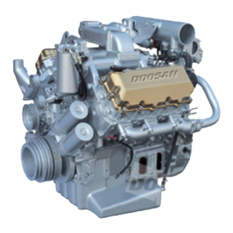
User Manuals: Doosan DV11 Diesel Engine
Manuals and User Guides for Doosan DV11 Diesel Engine. We have
1
Doosan DV11 Diesel Engine manual available for free PDF download: Operation And Maintenance Manual
Doosan DV11 Operation And Maintenance Manual (221 pages)
Brand:
Doosan
| Category:
Engine
| Size: 11 MB
Table of Contents
Foreword
2
Table of Contents
3
1 Safety Regulations & Engine Specifications
4
General Notes
4
To Prevent Accidents with Injury to Persons
4
To Prevent Damage to Engine and Premature Wear
6
Notes on Safety in Handling Used Engine Oil
7
To Prevent Pollution
7
General Repair Instructions
8
Engine Specifications
9
Engine Power
11
Engine Performance Curve
12
Engine Assembly
17
Engine Sectional View (Longitudinal)
17
Engine Sectional View (Cross)
18
Engine Assembly
19
2 Technical Information
21
Engine Model and Serial Number
21
Diagnostic Tool (SCAN-200)
21
Engine Character
22
Cylinder Block
23
Piston/ Connecting Rod/ Crank Assembly
23
Electric Control Unit : ECU
23
Common Rail System
24
Engine Timing
25
Valves
25
Lubrication System
26
Engine Oil
27
Oil Filter
28
Fan Belt
28
Air Cleaner
29
Pre Fuel Filter
29
Fuel Filter
29
Fuel Requirements
30
How to Select Fuel Oil
30
Fuel Oil Selection Chart
31
Fuel Injection System
32
Bleeding the Fuel System
32
Injector and High Pressure Connector
33
Inter Cooler
33
Turbo Charger
34
Cooling System
35
Coolant Pressure Cap
36
Cooling Water
36
Valve Clearance Adjust Procedure
38
Amount of Anti-Freeze in Winter
38
Adjusting of Valves
40
Adjusting of Engine Brake
40
Battery
41
Alternator
42
Regulator Connector
43
Wiring Diagram
43
Starting Motor
44
Diagnosis and Remedy
45
Engine Starting Impossible
45
Engine Overheated
46
Output Insufficient
47
Oil Pressure Lowered
48
Fuel Consumption Excessive
49
Oil Consumption Excessive
50
Battery Discharge
51
Engine Inspection
55
Stopping Engine
55
General Engine Inspection Cycle
55
3 Maintenance
55
Use of Original Parts for Repair and Replacement
56
Disassembly and Reassembly of Major Components
57
Engine Disassembly
57
General Precautions
57
Oil Level Gauge
58
Air Pipe and Air Heater
59
Cooling Fan and Fan Clutch
59
V-Belt
59
Turbocharger
60
Air Compressor
61
Power Steering Pump
61
Exhaust Manifold
62
Intake Manifold
62
Common Rail and High Pressure Pipe
63
Fuel High Pressure Pump
63
Water Pump
64
Fuel Pump Housing Cover
65
Oil Cooler
65
Vibration Damper
65
Cylinder Head Cover
66
Electric Control Unit
66
Engine Brake
66
Injector
67
Rocker Arm
67
Cylinder Head
68
Oil Pan
68
Oil Pump
68
Fly Wheel
69
Front Oil Seal Cover
69
Piston
69
Crank Shaft
70
Flywheel Housing
70
Cam Shaft & Tappet
71
Cylinder Liner
71
Oil Spray Nozzle
71
Cleaning and Inspection of Cylinder Block
72
Cylinder Head Disassembly
72
Cylinder Liner Measurement
72
Measurement and Inspection of Major Parts
72
Damage Check
73
Distortion of Lower Surface
73
Inspection and Measurement of Cylinder Head
73
Lower Face Warpage and Thickness
73
Inspection and Measurement of Valve and Valve Guide
74
Valve Head Thickness
74
Valve Stem Outer Diameter
74
Valve Guide
75
Valve Seat
75
Valve Stem End Play
75
Valve Seat Angle
76
Valve Seat Thickness
76
Valve Spring
77
Cylinder Head Assembling
78
Inspection and Measurement
79
Rocker Arm Ass`y
79
Rocker Arm Disassembling
79
Rocker Arm Specification
79
Clearance of Block and Tappet
80
Rocker Arm Reassembling
80
Run-Out
80
Tappet and Push Rod
80
Axial End Play
81
Cam Shaft
81
Inspection and Measurement of Camshaft
81
Cam Bearing Inside Diameter
82
Clearance
82
Camshaft Run-Out
83
Journal and Pin Diameter
83
"R” Part Standard Value
84
Journal and Pin Outside Diameter
84
Kinds of Bearings for Undersize
84
Crankshaft Bearing and Connecting Rod Bearing
85
Oil Clearance of Crankshaft and Bearing
85
Run out of Crankshaft
85
Bearing Oil Clearance
86
Journal and Connecting Bearing Inspection
86
Connecting Rod Bearing Clearance
87
Cylinder Block and Bearing Clearance
87
Crank Shaft End Play
88
Piston Disassembling
88
Check and Measurement
89
Cylinder Bore Diameter
89
Piston and Cylinder Clearance
89
Piston Ring and Ring Groove
90
Piston Ring Cut Part Clearance
90
Piston Side Clearance
90
Connecting Rod
91
Piston Pin
91
Piston Pin and Connecting Rod Bush Clearance
91
Injector Projection
92
Engine Reassembly
93
Preparation and Precaution before and after Engine Reassembly
93
Bearing Cap Bolt’s Tightening Order
95
Tappet
96
Front Oil Seal Holder
99
Connecting Rod Bolt Tightening Order
101
Oil Pump
101
Standard Length of Bolt and Use Limit
101
Intake and Exhaust Valve
103
Cylinder Head Bolts Tightening Order
104
Injector and High Pressure Connector Assembly Procedure
105
Fuel High Pressure Pump Housing Cover
108
Camshaft Speed Sensor
112
Crankshaft Speed Sensor
112
Reassembly
113
Starter
113
Power Take off (P.T.O)
114
Intake Stake and Air Heater
116
Thermostat
116
Alternator and Belt
117
Cooling Fan
118
Others
119
Common Rail Fuel-Injection System
120
Injection Characteristics with Common Rail
121
Major Components of the Common Rail System
121
Fuel Delivery Pump
123
Fuel System
123
Fuel Tank
123
High Pressure Fuel Delivery
124
High Pressure System Components
124
Construction of the Fuel High Pressure Pump
125
Fuel High Pressure Pipe
125
Function
125
Fuel Delivery Rate
126
Method of Operation
126
Common Rail
127
Fuel Metering Shut off Valve
127
Common Rail Pressure Sensor
128
Pressure Limiter Valve
129
Ethod of Operation
130
Injector Closed (at Rest Status)
131
Injector Closes (End of Injection)
131
Injector Opens (Start of Injection)
131
Cam Shaft Speed Sensor
132
Crank Shaft Speed Sensor
132
Accelerator Pedal Sensor
133
Boost Pressure and Temperature Sensor
133
Engine Coolant Temperature Sensor
133
Engine Oil Pressure and Temperature Sensor
133
Electrical Parts – Truck
134
Electrical System
134
Electrical Parts - Bus
135
Harness of Electrical Control Unit
136
Electrical Control Unit
139
Engine Harness
142
Harness of Injector and Engine Brake
143
Engine Brake Construction
147
Theory of Operation
148
Engine Brake Disassemble and Valve Adjustment
149
Engine Brake Operation Check
150
Solenoid Valve
150
Control Valve
151
Master Piston
151
Slave Piston
152
Troubleshooting
154
General Problem
155
Engine Diagnostic
158
Method by SCAN-200
158
Method of Confirmation for the Fault Code
158
Engine Diagnostic
159
Engine Fault Code and Occurring Condition
159
Input and Output of the ECU
162
Engine Idle Adjusting
163
Engine Starting
163
Operating Condition of the ECU
163
Vehicle Running
163
Cruise Control
164
Engine Brake Control
164
Maximum Speed Limit Function
165
Engine Stop During Long Time of Idling
166
Safety Function When Door Is Opened
166
Diagnostic
167
Limp Home Function
167
Power Take off (PTO)
168
Vehicle Operating Record
168
4 Commissioning and Operation
169
Preparations
169
Breaking-In
169
Operation of a New Engine (Break-In)
169
Check Points for Break-In
170
Inspections after Starting
171
Operating after Break-In
171
Pressure of Lubricating Oil
172
Temperature of Cooling Water
172
Over-Speed Control
172
Operation in Winter Time
173
Prevention against Freezing of Cooling Water
174
Air Heater Major Specification
174
Engine Components Check after Long Time Running
175
Prevention against Excessive Cooling
175
Lubricating Oil
175
Maintenance and Care
176
Periodical Inspection and Maintenance
176
Exchanging of Lubrication Oil
176
Oil Exchange Procedure
177
Replacement of Oil Filter Cartridge
177
Coolant Draining
179
Cooling System
179
Cleaning of the Cooling Inside System Circuit
180
Adjustment of Valve Clearance
181
General Information
181
Tightening the Cylinder Head Bolts
183
Cylinder Head Bolts
184
Cylinder Head Bolt’s Tightening Order
184
Cooling System
185
General Descriptions and Main Data
185
Specification
186
Inspecting
187
Replacing Thermostat and Precautions for Handling
187
Diagnostics and Troubleshooting
188
Disassemble the Drive Gear and Driven Gear
189
Disassembly of Oil Pump Drive Gear
189
Lubrication System
189
Remove the Oil Pump Cover
189
Inspection and Correction
190
Reassembly
190
With a Feeler Gauge, Measure
190
With Steel Rule and Feeler
190
Construction
192
Main Data and Specification
192
Operating Principle
192
Specification and Construction
192
Turbo Charger
192
Components of Turbocharger
193
Bearing
194
Compressor
194
Turbine
194
How to Handle the Engine
195
Precautions for Operation of the Engine
195
Sealing at Compressor Shaft
195
Air Intake System
196
Exhaust System
196
Routine Inspection and Maintenance
196
Guide for Checking Rotor End Play
197
Guide for Checking the Rotor for Rotating Condition
197
Lubricating System
197
Periodical Servicing
197
Guide for Disassembling/Cleaning and Checking the Turbocharger
198
Precautions for Reassembling the Turbocharger Onto the Engine
198
Rotor Axial Direction End Play
198
Rotor Radial Direction End Play
198
Changing Air Cleaner Element
201
Maintenance of Air Cleaner
201
Cleaning Air Cleaner Elements
202
Belt
203
Checking the Air Cleaner Cartridge
203
Knocking out Dirt by Hand
203
Measuring Tension
204
Reading of Tension
205
5 Maintenance of Major Components
185
6 Special Tool List
206
Appendix
209
Tightening Torque for Fuel Injection System
209
Tightening Torque for Major Parts
209
Standard Bolt Tightening Torque Table
210
Tightening Torque for Hollow Screw
210
Tightening Torque for Plug Screw
210
Maintenance Specification Table
211
Engine Assembly View
219
Advertisement
Advertisement
Related Products
Doosan D35S-5
Doosan D60S-5
Doosan DP180LBF
Doosan DP180LAF
Doosan DP222LCF
Doosan DE12T
Doosan D130S-5 with OCDB
Doosan DE08TS
Doosan D120
Doosan DP158L Series
Doosan Categories
Air Compressor
Engine
Forklifts
Excavators
Compact Loader
More Doosan Manuals
Login
Sign In
OR
Sign in with Facebook
Sign in with Google
Upload manual
Upload from disk
Upload from URL