Sign In
Upload
Manuals
Brands
Doosan Manuals
Compact Loader
DL550-5
Doosan DL550-5 Manuals
Manuals and User Guides for Doosan DL550-5. We have
3
Doosan DL550-5 manuals available for free PDF download: Operation & Maintenance Manual, Quick Start Manual, Shop Manual
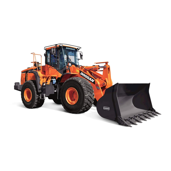
Doosan DL550-5 Operation & Maintenance Manual (393 pages)
Wheel Loader, Serial Number 10001 and Up
Brand:
Doosan
| Category:
Compact Loader
| Size: 34 MB
Table of Contents
Table of Contents
5
Foreword
9
Safety Messages
10
AEM Safety Manual (North America Only)
11
Intended Use
12
Product Information
12
Product Identification
13
Federal Emission Control Systems
14
Catalytic Converter
19
Safety
23
Safety Decals
24
Information and Location for Safety Decals
26
Safety Warnings
27
Transmission Oil Level
32
Pressure Check
34
Safe Operation
36
General
36
Pressurized Fluids
37
Flying or Falling Objects
38
Personal Protective Equipment (PPE)
38
Crushing and Cutting
39
Hot Coolant and Oils - Burn Prevention
40
Fire and Explosion Prevention
40
Safe Maintenance
41
Safe Fueling
42
Hydraulic System Checks
42
Welding and Grinding
43
If a Fire Occurs
43
Fire Extinguisher and First-Aid Kit (Emergency Medical Kit)
44
Electrical System and Electrical Shock
44
Roll-Over Protective Structure (ROPS)
45
Falling Object Protective Structure (FOPS)
45
Emergency Exit from Operator's Station
46
Operation
47
Before Engine Starting
47
Work Site
47
Check Tire Pressure and Condition
48
Mounting/Dismounting
48
Cleaning
49
Operator Station
49
Seat Belt
50
Visibility Information
51
Boost Starting or Charging Engine Batteries
52
Work Site Rules
52
Starting Engine
53
Traveling
53
Lifting and Digging
55
Digging Beneath Overhangs
55
Digging Beneath Wheel Loader
55
Operation on Slopes
56
Attachment
57
Equipment Lowering with Engine Stopped
57
Preventing Risk of Injuries or Death from Boom and Bucket
57
Engine Stop
59
Parking Machine
59
Maintenance
60
Warning Tag
62
Disassembling Precautions
63
Use of Lighting
64
Burn Prevention
65
Rubber that Contains Fluorides
66
Rubber and Plastics
67
Check List after Fire
67
Welding Repairs
68
Working on Machine
69
Preparation for Electrical Welding on Body Structure
69
Lock Inspection Covers
70
Accumulator
70
Compressed Air
70
Supports and Blocking for Work Equipment
71
High-Pressure Lines, Tubes and Hoses
71
Battery Hazard Prevention
72
Preservation/Storing Machine
73
Check after Long-Term Parking
74
Transportation
75
Loading and Unloading
75
Environment and Circumstances
77
Work Site Areas Requiring Extra Caution
77
Deep Digging
77
Drop-Off or Edge
77
Poor Visibility
78
Loose or Soft Ground
78
High-Voltage Cables
79
Underground Operation
79
Working in Water
80
Operation in Extreme Conditions
81
Operation in Extreme Cold
81
Operation in Extreme Heat
82
Operation in Dusty and Sandy Areas
83
Operation in Rainy or Humid Conditions
84
Operation in Saltwater Areas
84
Operation at High Altitudes
84
Operation During Electrical Storms
84
Exhaust Ventilation
85
Asbestos Information
85
Silica Dust Information
86
Disposal of Hazardous Materials
86
Sound Level Information
86
Vibration
87
Operating Controls
89
Component Locations
90
Operator's Area
93
Steering Console and Pedals
94
Horn Button (Two Places)
95
Combination Switch
96
Accelerator Pedal
97
Steering Wheel Adjustment Lever
97
Brake Pedal (Right and Left Pedals)
98
Steering Wheel
98
Kick-Down Button (Two Places)
99
Transmission Lever
99
Front Instrument Panel
100
Hour Meter
100
Front Keypad
101
Transmission Cutoff Switch
102
Load Isolation System (LIS) Switch
102
Transmission Torque Converter Lockup Switch
102
Hazard Warning Light Switch
103
Electric Steering High/Low Switch
104
Auto Grease System Switch
104
Differential Lock Button (Manual)
104
Warning and Indicator Lights
105
Front Instrument Panel
105
Password Activated
106
Speedometer
106
Multifunction Gauge and Graphic Information Display
106
Left Turn and Hazard Warning Light
107
Parking Brake Indicator Light
107
Right Turn and Hazard Warning Light
107
Brake Fluid Pressure Warning Light
108
Auto Grease Fault Indicator Light
108
Air Cleaner Clogged Warning Light
108
High Beam Indicator Light
108
Emergency Steering Indicator Light
109
Mirror Heater Indicator Light
109
Work Light Indicator Light
109
Information Display Switches
110
Multifunction Gauge and Graphic Information Display
110
Fuel Gauge
113
Engine Coolant Temperature Gauge
113
Transmission Oil Temperature Gauge
113
DEF (Adblue) Level Gauge
114
Transmission Actual Gear
114
Transmission Select Gear
114
Engine Speed
114
ECO Bar
115
Multifunction Gauge
115
Initializing Trip Meter
116
Switching Display to Battery Voltage
116
Display Warning Symbols
116
Charge Warning Symbol
117
Engine Oil Pressure Warning Symbol
117
Transmission Warning Symbol
117
Engine Warning Symbol
117
Water in Fuel Warning Symbol
118
DEF (Adblue) Low Level Warning Symbol - EPA
118
SCR Failure Warning Symbol
119
Indicator Symbols
120
Digital Clock
123
Warning Pop-Up
124
User Menu
126
Escape (ESC) Buttons
126
Vehicle State
127
Monitoring
127
Filter/Oil Information
127
Reset Method/Replacement Period Change Method
128
Symbol Description
129
Vehicle Configuration
130
Vehicle Information
130
Total Fuel Used
130
Reverse Fan Auto Period Setting
131
Active LIS Vehicle Speed Setting
131
Auto Shut off Time Setting
132
Auto Idle Enable/Disable State
132
GP Configuration
133
Password Setting
133
Screen Brightness Setting
134
Default Screen Setting
135
Time Setting
136
Service Phone Number Setting
137
Unit Setting
138
Language Setting
138
Notification Setting
139
Right Side Switch Panel
140
FNR Lever (Standard)
141
Finger Tip Lever
142
Pilot Control Valve Lever (Electric Lever)
144
Starter Switch
145
Parking Brake Switch
146
Pilot Cutoff Switch
146
Headlight Switch
147
Stand Keypad
147
Power Mode Switch
147
Optimized Engine/Work Mode
148
Transmission Shift Switch
148
Front Work Light Switch
149
Rear Work Light Switch
149
Rear Wiper Switch
149
Cooling Fan Reverse Rotation Switch
150
Mirror Heating Switch
150
Fuel Heater Switch
150
Rotating Beacon Light Switch
151
Emergency Steering Test Switch and Automatic Test
151
Hands-Free Control Panel
152
Call Button
152
Mode Selector Button
152
Volume - up Button
152
How to Use the Hands-Free System
153
Mode Confirm Light
153
Power Socket for 12 Volt
155
Cigarette Lighter
155
F/R (Forward/Reverse) Selector Switch
155
F/R (Forward/Reverse) Control Switch
156
Left Side Electric Steering Control Unit (Optional)
157
Electric Steering Selector Switch
158
3Rd FNR Control Switch
158
Kick-Down Button
158
Electric Steering Joystick
159
Armrest Cutoff Switch
159
Various Cabin Locations
160
Cabin Light
161
Storage Compartments
162
Electrical Box
162
Emergency Starter Switch
163
Heater and Air Conditioner Operation
164
Location of Controls and Vents (Heater and Air Conditioner)
164
Automatic Temperature Control Button
165
Temperature Control Button
166
Temperature Unit Selector Button
166
Air Inlet Selector Button
168
Fan Speed Selector Buttons
168
Air Conditioner Button
168
Memory Function
169
Additional Operating Instructions
169
Defroster Button
169
LCD Display
169
Stereo/CD Player (Optional)
170
Seat Adjustment W/Air Suspension (Standard)
171
Adjusting Seat Forward/Backward Lever
171
Seat Height and Weight Adjustment Knob
171
Backrest Adjustment Lever/Lumbar Control Knob
171
Angle Adjustment of Armrest
172
Adjustment of Upper Backrest
172
Heating Operator's Seat
172
Recommendations for Limiting Vibrations
173
Seat Adjustment W/Air Suspension and Heater
174
Seat Height and Firmness/Adjustment Knob
174
Seat Belt Locking and Unlocking
176
Door Side Latch
177
Arm Rest
178
Fuse Box/Relay
179
Fuse Identification
180
Relays
181
Circuit Breaker
181
Fusible Link
181
Wheel Chocks
182
To Operate a New Wheel Loader
183
Monitoring System
183
New Machine Break-In Procedures
183
Operation
183
Inspection before Starting Engine
184
Starting and Stopping Engine
184
Engine Start
188
After Start Limit Logic
192
Automatic Warming up Operation
192
Engine Speed Range
192
Plug Heater
193
Check Oil Bath Precleaner
194
Emission Control System
195
Reaction to Faults in SCR System (Only EPA)
195
Coolant Temperature
196
Charging Indicator Light
197
Engine Oil Pressure
197
Stopping Engine
197
Checks and Maintenance after Stopping Engine
199
Machine Travel
200
If Engine Stalls While Traveling
203
Working in Water
203
Towing
204
F/R (Forward/Reverse) Travel Control System
206
Machine Shut down
207
Arm Angle Sensor Switch
209
Bucket Angle Indicator
209
Operation of Attachment
209
Adjustment of Bucket Position Switch
210
Bucket Angle Sensor Switch
210
Operation under Abnormal Conditions
211
Long Term Storage
216
After Storage
217
Auto Grease System (Optional)
218
Location
220
Lubricants
221
Lubricant Filling
224
Lubricant Hazards
224
Filler Coupling
225
Filling Cylinder
225
Pump Display and Control Elements of Control Screen
227
Three-Digit LED Display
228
LED Display
230
Pump Display Mode
231
Change Lubrication Interval Times
233
Pump Programming
233
Configure System Monitoring
234
Change Operating Modes
235
Change Access Code
236
Display Ranges
237
Programming Ranges
237
Display Faults
240
Troubleshooting
240
Fault Types
241
Maintenance and Repair
242
Recording Fault Times
242
Block Operation
243
Duration of Block Pause
243
No Signal from Piston Detector During Pump Cycle
243
Malfunctions on Pump Units
244
Inspection, Maintenance and Adjustment
247
Maintenance Information
247
Welding Instructions
248
Hydraulic Hose Installation
249
Checks after Inspection and Maintenance Works
249
Safety Precautions
250
Machine Setup Position for Maintenance
251
Maintenance Handling Access
253
Entering/Leaving/Climbing on Machine
253
Service Position
254
Service Points
255
Handling Oil, Fuel, DEF (Adblue) Coolant
256
DEF (Adblue)
258
Non-Permitted Container Materials for Storing DEF (Adblue)
258
Allowable DEF (Adblue) Storage Days
258
Coolant and Water for Dilution
259
Grease
259
Electrical System Maintenance
260
Filters
260
Recommend Fuel, Coolant, and Lubricant
261
Fire Prevention Measures
264
Working on Painted Surfaces
265
Methods and Precautionary Measures When Removing Paint
266
Preventive Maintenance
268
Product Identification Number (PIN) Location
268
Component Serial Numbers
269
Engine Identification
269
Engine Data Plate
269
Table of Recommended Lubricants
270
Recommended Grease for Auto Grease System
271
Recommended DOOSAN Genuine Grease for Auto Grease System
271
Transmission Oil
273
Oil Grade of Transmission
273
Oil Change Intervals
273
Load Class
273
Axle Oils
274
Oil Grade ZF-Powerfluid
274
Fluid Capacities
275
Engine Oil Drain Intervals by Duty Cycle (Hours)
275
Lubrication and Service Chart
276
Greasing Bearings
276
Symbols for Lubrication and Service Chart
277
Maintenance Intervals
280
10 Hour / Daily Service
282
Grease Front Attachment Pins
282
Check Engine Oil Level
282
Check Transmission Oil Level
283
Check Hydraulic System Oil Level
284
Check for Leaks in Hydraulic System
285
Fill Fuel Tank
285
Check for Leaks in Fuel System
286
Drain Fuel Condensation
286
Fill DEF (Adblue) Tank
286
Check Coolant Level
287
Check Level of Windshield Washer Liquid
287
Inspect Bucket Teeth and Side Cutters for Signs of Wear
288
Inspect Cooling Fan Blade
288
Check Engine Air Intake Precleaner
288
Check Air Intake System
289
Inspect Structure for Cracks and Faulty Welds
289
Inspect Seat Belt for Proper Operation
289
Inspect Mirrors for Damage and Adjust and Clean as Required
289
Check Operation of All Switches
290
Check Operation of All Exterior Lights, Horn and Control Console Indicator and Monitor Lights
290
Start Engine, Check Starting Ability, and Observe Exhaust Color at Start-Up and at Normal Operating Temperature. Listen for any Abnormal Sounds
290
Check that Back up Alarm and Rear Camera (if Equipped) Is Working Properly
290
Inspect All Tires for Correct Tire Pressure and Signs of Damage or Abnormal Wear
290
Check Operation of All Controls and Linkages
291
50 Hour / Weekly Service
292
Perform All Daily Service Checks
292
Grease Front Attachment Pins
292
Grease Steering Cylinder Rod and Head Ends
293
Grease Upper and Lower Center Pins
294
Change Engine Oil and Filter (after First 50 Hours)
295
Change Hydraulic Full Flow Filter (after First 50 Hours)
295
Clean Exterior of Radiator, Oil Cooler and Air Conditioner Condenser
295
Check Air Conditioner and Alternator Belt Tension (after First 50 Hours)
295
Clean Air Conditioner Outer Filter
296
Perform All Daily and 50 Hour Service Checks
297
Braking - Test
297
250 Hour / Monthly Service
297
Parking Brake Test
299
Drain Water from Hydraulic Oil Tank
301
Grease Front Attachment Pins
302
Check Air Conditioner Belt Tension
304
Grease Driveshafts
304
Change Transmission Oil and Filter (after First 250 Hours)
305
Fuel Water Trap
305
Auto Grease System (if Equipped)
305
Clean Oil Bath Precleaner (Optional)
306
Clean Outer Air Cleaner Filter
308
500 Hour / 3 Month Service
308
Change Hydraulic System Brake and Pilot Filter
310
Change Engine Oil
311
Change Engine Oil Filter
312
Clean Centrifugal Oil Cleaner
313
Check and Adjust Valve Clearance
315
Clean Air Conditioner Inner Filter
316
Check Hydraulic Oil Contamination
317
Change Water Separator
318
1,000 Hour / 6 Month Service
318
Change Fuel Filter
319
Bleeding Fuel System
321
Change DEF (Adblue) Breather Filter
322
Change DEF (Adblue) Filter
323
Drain and Change Transmission Oil and Filter
324
Change Air Conditioner Inner Filter
325
Check and Adjust Engine
325
Clean Fuel Tank and Strainer
326
Check Air Conditioner Refrigerant
327
Change Air Breather Filter
328
Change Hydraulic Full Flow Filter
329
Change Fuel Cap Filter
330
Check Drive Belt
332
Change Axle Differential and Planetaries Oil
333
1,500 Hour / 9 Month Service
333
Change Outer Air Cleaner Filter
335
Change Inner Air Cleaner Filter
335
Change Pipes and Hoses
335
2,000 Hour / Yearly Service
335
Change Radiator Coolant
336
Change Hydraulic Oil and Clean Oil Suction Strainer
337
Bleed Brakes
339
Check Brake Accumulator
340
Hose In-Service Lifetime Limit
341
12,000 Hour / 6 Year Service
341
Standard Bolt Torque Chart
342
Check Battery Condition
343
Electrical System
343
Engine Cooling System
344
Types of Antifreeze
345
Antifreeze Concentration Tables
346
Table of Standards for Allowed Tap Water
346
Handling of Accumulator
347
Pilot Accumulator
347
Brake Accumulators
348
LIS Accumulator
348
Steering Accumulator
348
Hydraulic Pressure Checks
349
Steering Pump Load Sensing Pressure
349
Pilot Supply Pressure
349
Main Pump Pressure
350
Brake Charging Pressure
350
Steering Pump Pressure
350
Transmission Clutch Pressure
351
Main Pump Load Sensing Pressure
351
Fan Motor Pressure and Fan Speed
352
Checking Maximum Fan Speed, Checking
353
Long Term Storage
354
Parking Brake Adjustment
355
Emergency Release of Parking Brake
355
Adjustment Procedure for Parking Brake
356
Severe Conditions Maintenance
357
Inflating Tires
358
Wheel Nut, Tightening Check
358
Wheel Nut Torque
359
Check Tire for Damage
359
Recommended Air Pressure
360
Transmission Recalibration
361
Transporting Machine
363
Transportation
363
Unloading
366
Lifting Machine
367
Braking Troubleshooting
369
Electrical System Troubleshooting
370
Engine Troubleshooting
370
Hydraulic System Troubleshooting
373
Steering Troubleshooting
375
Travel System Troubleshooting
376
General Specifications
379
Working Range and Dimensions
380
Bucket Capacity
382
Working Capacities
382
Approximate Weight of Workload Materials
383
Material Weight
383
Index
385
Advertisement
Doosan DL550-5 Quick Start Manual (60 pages)
Brand:
Doosan
| Category:
Front End Loaders
| Size: 1 MB
Table of Contents
Safety Messages
3
Personal Protective Equipment
4
Machine Access
5
Safety Signs
6
Tyre Pressure
9
Side Console
21
Cold Start Procedure
47
Reversing Fan
49
Auto Shut off
50
Air Conditioning
52
Doosan DL550-5 Shop Manual (14 pages)
Wheel Loader
Brand:
Doosan
| Category:
Compact Loader
| Size: 1 MB
Table of Contents
Specifications
2
Safety Instructions
6
Safety Messages
6
Safety Alert Symbol
6
Advertisement
Advertisement
Related Products
Doosan DL550-3
Doosan DL550
Doosan DL500
Doosan DL250A
Doosan DL300-3
Doosan DL350-3
Doosan DL250-3
Doosan DL300A
Doosan DL300
Doosan DL400
Doosan Categories
Air Compressor
Excavators
Engine
Forklifts
Compact Loader
More Doosan Manuals
Login
Sign In
OR
Sign in with Facebook
Sign in with Google
Upload manual
Upload from disk
Upload from URL