Sign In
Upload
Manuals
Brands
DLoG Manuals
Desktop
MPC 6
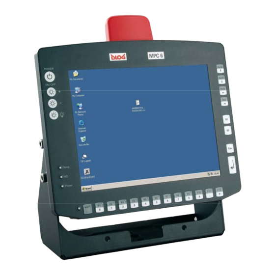
User Manuals: DLoG MPC 6 Industrial Computer
Manuals and User Guides for DLoG MPC 6 Industrial Computer. We have
1
DLoG MPC 6 Industrial Computer manual available for free PDF download: Manual
DLoG MPC 6 Manual (223 pages)
Brand:
DLoG
| Category:
Desktop
| Size: 2 MB
Table of Contents
Table of Contents
5
1 About this Manual
17
Device Version Described
17
For Qualified Personnel
17
Design Method
18
Warnings and Notices
18
Additional Design Elements
18
2 Important Safety Notices
20
Initial Operation of the Device
20
Power Supply/External Peripheral Devices
22
Repairs Only through Dlog
23
Opening and Closing the Device
24
Exchanging and Extending Modules
26
CE Marking
28
RTTE Directive 1999/5/EC
28
Special Regulations in France
28
Figure 2.1: CE Marking
28
FCC User Information
29
Interference Declaration of the Federal Communications Commission
29
Transmission of Radio Frequencies
30
3 Device Description
31
General
31
Figure 3.1: Dlog MPC 6 with Optional Mount
31
Intended Usage
32
The Models: Dlog MPC 6/110 and Dlog MPC 6/112
32
Abbreviations Used for Devices and Accessories
32
Device Description and Type Identification
33
Device Type Plate
33
Figure 3.2: Example of a Device Type Plate
34
Technical Specifications
35
Mechanical
35
Motherboard
36
LCD/CRT Interface
38
Touch Screen (Optional)
38
Network Interface
39
ADC/MDC Interface (Optional)
39
Cardbus Interface (Optional)
39
PCI Express® Minicard Interface for WLAN (Optional)
40
Power Supply
41
Maximum Power Available for Peripheral Devices
42
Power Supply Fuses
43
Ambient Conditions
44
Test Marks
45
Dimensions
46
Figure 3.3: Dlog MPC 6/110 SVGA Front View
46
Figure 3.4: Dlog MPC 6/110 SVGA Side View
47
Figure 3.5: Dlog MPC 6/110 SVGA Top View
48
Figure 3.6: Dlog MPC 6/112 Front View
49
Figure 3.7: Dlog MPC 6/112 Side View
50
Figure 3.8: Dlog MPC 6/112 Top View
51
VESA Drill Holes
52
Figure 3.9: Dlog MPC 6/110 with VESA Drill Holes
52
4 Unpacking the Dlog MPC 6
53
Scope of Delivery
53
Packaging
53
Returning Your Device
53
5 Putting Your Dlog MPC 6 in Operation
54
Cooling through the Supply of Fresh Air
54
Pin Configuration
55
External Connectors
55
Figure 5.1: External Connectors, AC Version
55
Figure 5.2: External Connectors, 24/48 VDC 60 W Version
55
Figure 5.3: External Connectors, 24/48 VDC 100 W Version
56
Figure 5.4: External Connectors, 12 VDC 100 W Version
56
AC Voltage Supply Connector
57
DC Voltage Supply Connector
57
Figure 5.5: Exterior View of the AC Power Supply Connector
57
Figure 5.6: Exterior View of the DC Power Supply Connector
57
Figure 5.7: Cable Diagrams of the DC Device's Supply Connection
58
Connecting External Devices
59
Powering down the Dlog MPC 6
60
WLAN Settings
61
Radio Performance
61
Dlog Antenna Solutions for Use in Germany
62
Removing the Protective Film from the Display
62
Powering up the Dlog MPC 6
63
Protecting the TFT Display from the Memory Effect
63
6 Accessories
64
Keyboard
64
SMALL Keyboard
64
Figure 6.1: SMALL Keyboard on the Dlog MPC 6
64
24-Key Keypad
65
Figure 6.2: 24-Key Keypad on the Dlog MPC 6
65
Mouse
66
External CD-ROM Drive
67
External Floppy Disk Drive
68
USB Stick
69
Scanners
69
WLAN Cards (PC Card, Cardbus, Pcie Minicard)
69
7 Installation
70
Options for Installing the Device
70
Permitted Mounting Positions
71
Figure 7.1: Permitted Mounting Positions of the Dlog MPC 6
71
Follow and Retain the Installation Instructions
72
Mechanical Dynamic Loading
72
Power Supply
73
AC Power Pack
73
DC Power Pack
74
Installing Connecting Cables
75
Vehicle Applications (such as Forklifts)
75
Figure 7.2: Position of the Ground Bolt
76
Cable Cover (Splash Guard)
77
Protection Class IP65
77
Figure 7.3: Dlog MPC 6 with Strain Relief
77
Protection Class IP54
78
Figure 7.4: Dlog MPC 6 Without Cable Cover
78
Figure 7.5: Dlog MPC 6 with Cable Cover Mounted
79
8 Operation
80
Key Front Panel
80
Figure 8.1: Dlog MPC 6 Front Panel with 4 Keys
80
Key Front Panel
81
Figure 8.2: Dlog MPC 6 Front Panel with 10 Keys
81
Key Front Panel
82
Figure 8.3: Dlog MPC 6 Front Panel with 25 Keys
82
Power Key
83
Leds
84
Manual Brightness Control/Backlighting
84
Function and Number Keys
85
Special Keys
85
Escape Key, Enter Key and Scroll Keys
86
Operating States
87
9 Operating System
88
Pre-Installed on the Hard Drive/Compact Flash
88
Installing on the Hard Drive/Compact Flash
89
Operating Systems Supplied on CD-ROM
89
Operating System Images
90
Operating Systems on Floppy Disk
90
Special Features of the Operating Systems
91
Ms-Dos
91
Windows XP Embedded
91
Linux
91
10 Software Applications
92
Displaying the Configuration of the Dlog MPC 6
92
Fine Tuning the Operating System Parameters
92
Environment Controller Settings
93
11 Serial Ports
95
Resources
95
COM1 Options
95
COM1 as a Power Supply
95
COM2 Options
96
COM2 as Electrically-Isolated RS-422/485
96
Drivers
97
Operation
97
RS-4Xx Operation
97
Serial Port Printers
97
Serial Port Barcode Scanners
98
Tips & Tricks
99
12 Internal Devices
100
Chipset
100
Installing Chipset Drivers under MS-DOS
100
Installing Chipset Drivers under Windows XP
100
Figure 12.1: Welcome Screen for Chipset Driver Installation
101
VGA Adapter
102
VGA Driver Installation under MS-DOS
102
VGA Driver Installation under Windows XP
102
Figure 12.2: Welcome Screen for the VGA Driver Installation
103
Network Adapter (10/100)
104
Figure 12.3: RJ45 Network Port
104
Figure 12.4: Network Driver Installation License Agreement
105
Network Driver Installation under MS-DOS
105
Network Driver Installation under Windows XP
105
Figure 12.5: Start Screen for Network Driver Installation
106
Onboard Sound Adapter
107
Installation of the Onboard Sound Adapter Drivers (Win XP)
107
Figure 12.6: Welcome Screen for the Onboard Sound Adapter Drivers
107
Figure 12.7: Warning Message for the Onboard Sound Adapter Drivers
108
Touch Screen
109
MS-DOS Installation and Calibration for Driver Version 5.06
110
Touch (Serial) for Windows XP Prof. and XP Embedded
112
Installation
112
Figure 12.8: "Files Needed" Touch Installation Dialog
113
Calibration
114
Touch (PS2) for Windows XP Prof. and XP Embedded
115
Installation
115
Figure 12.9: "Setup Message" Touch Installation Dialog
115
Calibration
116
Resistance of the Touch Screen
117
Plug-In Cards
119
Riser Card with 1X PCI
120
Terratec 128I PCI Sound Card
120
CAN Card
120
Automatic Switch-Off and Heating
121
Automatic Shutdown Process
122
Program Flowchart
123
Figure 12.10: Automatic Shutdown Program Flowchart Part 1
123
Figure 12.11: Automatic Shutdown Program Flowchart Part 2
124
Drivers
125
General Notes about the Automatic Shutdown Software in Windows
126
13 Maintenance
127
Cleaning the Housing
127
Touch Screen Cleaning
127
14 Common Mistakes in Usage
128
Power Supply
128
Powering Up/Down
128
Cable Cover
128
Installation
129
Mobile Application on Vehicles
129
Using the Touch Screen
130
Use/Storage in Extreme Temperatures
130
15 Disposal
131
16 Appendix A: System Resources
132
Part 1
132
Part 2
134
17 Appendix B: Terminal Assignment (Pins)
135
External Connectors
135
Keyboard and Mouse
135
Usb
136
Serial Port COM1
136
Serial Port COM2
137
Network Connector
138
Internal Connectors, Motherboard MPC6.20
139
Cardbus Connector
140
Input Voltage Connector
142
Ignition Signal Connector
142
Heating Power Connectors
143
Serial Port COM2
143
Audio Port
144
IDE Connector
145
Compact Flash Connector
146
LCD Connector
147
Front Keyboard Connector
148
Inverter Connector
148
Touch Connector
149
Riser Card Connector
150
Internal Connectors, Riser Card
151
Figure 17.1: Internal Connectors, Riser Card 1 X PCI
151
PCI Connector
152
VGA Interface (for Service Purposes Only)
155
COM4 Connection
156
USB Post 3 and 4
157
Pcie Minicard Socket
158
18 Appendix C: Jumper
159
Warnings
159
Standard Jumper Settings
159
Jumper Layout View, Motherboard
160
Figure 18.1: Jumper Layout, Motherboard MPC6.20 06.2006
160
Battery
161
Compact Flash Configuration
161
Ethernet Configuration
161
Touch Configuration
162
Touch Enable
162
COM1 Configuration
163
LCD Configuration
163
Compact Flash DMA Configuration
164
External Shield Connection
164
Touch Interface Selection
164
19 Appendix D: Tools
165
Please Follow the Safety Notices
165
Dlog MPC 6 Toolkit
166
Figure 19.1: Dlog MPC 6 Toolkit
166
Mounting Bracket Toolkit
167
Figure 19.2: Mounting Bracket Toolkit
167
20 Appendix E: Mechanical Dynamic Loading
168
20. Appendix E: Mechanical Dynamic Loading
168
Introduction
168
Using the Device Without Vibration Insulation (Tuned to a High Frequency)
170
Use with Passive Vibration Insulation (Tuned to a Low Frequency)
171
Dimensioning Example Dlog MPC 6/110
172
Figure 20.1: Table-Top Attachment with Elastomer Springs
173
Approximate Solution for the Selection of Elastomer Springs
174
Further Possible Steps for Optimization
176
Approximate Solution for Determining Insulating Effects
177
Determining Natural Frequencies
179
21 Appendix F: BIOS
180
21. Appendix F: BIOS
180
BIOS Setup Description
180
Setup Menu and Navigation
181
Main Setup Screen
182
Figure 21.1: BIOS Advanced Setup
184
ACPI Configuration Submenu
185
PCI Configuration Submenu
186
Graphics Configuration Submenu
188
CPU Configuration Submenu
190
I/O Interface Configuration Submenu
191
IDE Configuration Submenu
192
USB Configuration Submenu
196
Keyboard/Mouse Configuration Submenu
198
Remote Access Configuration Submenu
199
Hardware Monitoring Submenu
201
Watchdog Configuration Submenu
202
Boot Setup
204
Boot Device Priority
205
Boot Settings Configuration
206
Figure 21.2: BIOS Security Setup
207
Security Settings
208
Hard Disk Security
209
Figure 21.3: BIOS Exit Menu
210
Additional BIOS Features
211
Figure 21.4: BIOS Updating under Windows 1
213
BIOS Security Features 1
215
Hard Disk Security Features 2
216
Return Packing Slip 2
217
Index
218
Advertisement
Advertisement
Related Products
Dlog MTC 6
DLoG Categories
Touch terminals
Desktop
Tablet
Industrial PC
More DLoG Manuals
Login
Sign In
OR
Sign in with Facebook
Sign in with Google
Upload manual
Upload from disk
Upload from URL