Table of Contents
Advertisement
Quick Links
Advertisement
Table of Contents

Summary of Contents for DLoG MPC 6
- Page 1 DLoG MPC 6 Manual 1.01...
- Page 2 We reserve the right to modify the contents of this document at any time and without prior notice. Because we at DLoG are constantly striving to improve this product, we cannot guarantee that previous or subsequent releases of the product will correspond in every respect with the product description given in this manual.
-
Page 5: Table Of Contents
Transmission of radio frequencies..............14 Device description................15 3.1. General ........................15 3.2. Intended usage ......................16 3.3. The models: DLoG MPC 6/110 and DLoG MPC 6/112...........16 3.4. Abbreviations used for devices and accessories.............16 3.5. Device description and type identification ...............17 3.5.1. Device type plate .....................17 3.6. - Page 6 4.1. Scope of delivery ..................... 37 4.2. Packaging........................ 37 4.3. Returning your device....................37 Putting your DLoG MPC 6 in operation ..........38 5.1. Cooling through the supply of fresh air..............38 5.2. Pin configuration...................... 39 5.3. External connectors....................39 5.3.1.
- Page 7 Accessories ..................48 6.1. Keyboard........................48 6.1.1. SMALL keyboard .....................48 6.1.2. 24-key keypad ....................49 6.2. Mouse ........................50 6.3. External CD-ROM drive ...................51 6.4. External floppy disk drive..................52 6.5. USB stick .........................53 6.6. Scanners........................53 6.7. WLAN cards (PC card, cardbus, PCIe minicard).............53 Installation.....................54 7.1.
- Page 8 9.3.2. Windows XP Embedded.................. 75 9.3.3. Linux ........................ 75 Software applications ..............76 10.1. Displaying the configuration of the DLoG MPC 6..........76 10.2. Fine tuning the operating system parameters............. 76 10.3. Environment controller settings ................77 Serial ports..................79 11.1.
- Page 9 Internal devices.................84 12.1. Chipset.........................84 12.1.1. Installing chipset drivers under MS-DOS ............84 12.1.2. Installing chipset drivers under Windows XP ..........84 12.2. VGA adapter ......................86 12.2.1. VGA driver installation under MS-DOS ............86 12.2.2. VGA driver installation under Windows XP ..........86 12.3. Network adapter (10/100) ..................88 12.3.1.
- Page 10 Maintenance..................111 13.1. Cleaning the housing..................111 13.2. Touch screen cleaning ..................111 Common mistakes in usage ............112 14.1. Power supply ..................... 112 14.2. Powering up/down..................... 112 14.3. Cable cover ....................... 112 14.4. Installation ......................113 14.5. Mobile application on vehicles................113 14.6.
- Page 11 18.3.6. COM1 configuration...................147 18.3.7. LCD configuration..................147 18.3.8. Compact Flash DMA configuration............148 18.3.9. Touch interface selection................148 18.3.10. External shield connection.................148 Appendix D: Tools ................149 19.1. Please follow the safety notices ................149 19.2. DLoG MPC 6 toolkit ...................150 19.3. Mounting bracket toolkit..................151...
- Page 12 Using the device without vibration insulation (tuned to a high frequency) ..154 20.3. Use with passive vibration insulation (tuned to a low frequency)...... 155 20.4. Dimensioning example DLoG MPC 6/110 ............156 20.4.1. Approximate solution for the selection of elastomer springs ....158 20.4.2.
- Page 13 21.8. Exit menu......................194 21.9. Additional BIOS features ...................195 21.9.1. Updating the BIOS..................195 21.10. BIOS recovery....................1 99 5 4 3 H 2 1.11. BIOS security features..................1 99 2 4 6 H 5 4 4 H 2 1.12. Hard disk security features ................2 00 2 4 7 H 5 4 5 H...
- Page 14 Figure 6.1: SMALL keyboard on the DLoG MPC 6 ............48 Figure 6.2: 24-key keypad on the DLoG MPC 6 ..............49 Figure 7.1: Permitted mounting positions of the DLoG MPC 6 ........55 Figure 7.2: Position of the ground bolt ................60 Figure 7.3: DLoG MPC 6 with strain relief................61 Figure 7.4: DLoG MPC 6 without cable cover ..............62...
- Page 15 Figure 12.11: Automatic shutdown program flowchart part 2.........108 Figure 17.1: Internal connectors, riser card 1 x PCI............135 Figure 18.1: Jumper layout, motherboard MPC6.20 06.2006 ........144 Figure 19.1: DLoG MPC 6 toolkit..................150 Figure 19.2: Mounting bracket toolkit ................151 Figure 20.1: Table-top attachment with elastomer springs ..........157 Figure 21.1: BIOS advanced setup ................168...
-
Page 17: About This Manual
About this manual 1. About this manual This manual has been designed to make using the DLoG MPC 6 as simple as possible and provide expert assistance if problems should occur. It contains important information on using the device safely, properly and efficiently. -
Page 18: Design Method
You must heed this information! 1.3.2. Additional design elements Lists are indicated with bullet points, for example: • DC power packs • AC power packs Instructions are numbered, for example: 1. Insert a CD. 2. Press <A>. Manual DLoG MPC 6... - Page 19 Any text that needs to be entered is shown in Courier font, for example: 1. Enter the text abcdefg. Other methods for emphasis Any other emphasized text elements are highlighted in bold or underlined. References to other chapters in the manual are printed in italics. DLoG MPC 6 Manual...
-
Page 20: Important Safety Notices
Important safety notices 2. Important safety notices The DLoG MPC 6 was designed and built according to modern technology and accepted safety regulations. However, the operation of the DLoG MPC 6 can endanger personnel or third parties and cause damage to the device and other material assets when for example the device is •... - Page 21 If the DLoG MPC 6 is not able to draw in fresh cooling air, this may cause overheating and severe damage to the unit.
-
Page 22: Power Supply/External Peripheral Devices
DLoG MPC 6 is not exceeded. (see sections 3.6.9 and 7.5). Wiring Do not use the DLoG MPC 6 when a cable or plug is damaged. Have the damaged parts replaced immediately! Do not connect or disconnect any cables during storms Data cables must never be connected or disconnected during an electrical storm. -
Page 23: Repairs Only Through Dlog
On the back of the DLoG MPC 6 you will find the device’s type plate which has important information about the device which you must quote for technical service. It provides important information about the configuration and manufacture of the device in abbreviated form. -
Page 24: Opening And Closing The Device
Important safety notices 2.4. Opening and closing the device If you choose to open the DLoG MPC 6 at your own risk, please make sure you observe the safety instructions from the previous pages. Persons authorized to open and close the device The DLoG MPC 6 may only be opened for the purposes of adding or exchanging modules. - Page 25 Important safety notices Device seal The face of the DLoG MPC 6 device has a protective seal glued into its frame. Do not attempt to remove the seal from the face, as this will cause irreversible damage to the seal and render it unusable.
-
Page 26: Exchanging And Extending Modules
No battery changes The DLoG MPC 6 motherboard is powered by a lithium ion battery which is fixed to the motherboard. This battery should not be replaced under any circumstances, as this requires soldering! Should a battery replacement be necessary, the device must be sent to DLoG. - Page 27 System overloads To avoid system overloads, check the sum load of all components installed. Make sure that the input current for each consumer falls within the appropriate boundaries (see: the technical data for each corresponding consumer). DLoG MPC 6 Manual...
-
Page 28: Ce Marking
DLoG MPC 6 (see page 2 of this handbook) apply. 2.7.1. Special regulations in France Due to restrictions imposed by the French government, the DLoG MPC 6 with WLAN 802.11b is only permitted for use indoors. On private property the product is allowed to be used outdoors, however only with previous approval from France’s Ministry of Defense. -
Page 29: Fcc User Information
In order to comply with the FCC requirements regarding radio frequency exposure from vehicle-mounted transmission devices the antenna has to be kept at least 20 cm away from people. DLoG MPC 6 Manual... -
Page 30: Transmission Of Radio Frequencies
Do not place the DLoG MPC 6 near such devices. Keep a minimum distance of 20cm between such a device and the DLoG MPC 6 in order to reduce the risk of interference. If you have reason to assume that interference has occurred, then turn the DLoG MPC 6 off and consult a heart expert. -
Page 31: Device Description
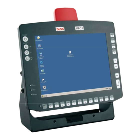
3.1. General Thank you for choosing the DLoG MPC 6. The DLoG MPC 6 is a multi-function PC designed for stationary and mobile use. Thanks to its rugged design (aluminum housing), the device provides effective protection against mechanical, electrical and chemical influences and extreme ambient temperatures. It is designed without an external fan to reduce maintenance requirements. -
Page 32: Intended Usage
Device description 3.2. Intended usage The DLoG MPC 6 is a multifunction terminal for stationary and mobile use in commercial applications (for example logistics, storage, manufacturing). A different or extraordinary usage is not permitted. For resulting damage the user/operator of the DLoG MPC 6 is solely responsible. This also applies to any changes you make to the device. -
Page 33: Device Description And Type Identification
Device description 3.5. Device description and type identification 3.5.1. Device type plate The device type plate on the DLoG MPC 6 contains the following information: DLoG MPC 6 Describes the device DLoG MPC 6 with a connection level and a 10” or 12” display... -
Page 34: Figure 3.2: Example Of A Device Type Plate
Device description Example of a device type plate Figure 3.2: Example of a device type plate Manual DLoG MPC 6... -
Page 35: Technical Specifications
Housing Rugged aluminum-cast housing with integrated heat sink Protection class IP54 (upgradeable to IP65) ESD safe Weight of the DLoG MPC 6 with a 10.4” front panel: approx. 4.0 kg (depending on configuration) Display panel 10.4" SVGA, 230 cd/m , optional 4-wire resistive touch screen , with brightness adjustment 10.4"... -
Page 36: Motherboard
2.5" Flash disks (IDE) (enquire which capacities are currently available) Compact Flash type I/II Important notes for Compact Flash Cards: Only use Compact Flash Cards approved and released by DLoG to ensure the device functionality. Otherwise data loss could increase. Manual... - Page 37 Device description The Compact Flash Cards used in the DLoG MPC 6 must be industrial and non removable models. Floppy disk drive Supports an external 3.5” USB floppy disk drive Protected to ESD level 4 (according to EN 61000-4-2) Optional...
-
Page 38: Lcd/Crt Interface
Drivers available for MS-DOS 6.2x, Windows XP Professional, XP Embedded and Linux Analog touch Available for 10.4” and 12.1” LCD displays, others on request screens Analog touch Internal plug-in connector connection Interface is ESD level 4 protected (acc. to EN 61000-4-2) Manual DLoG MPC 6... -
Page 39: Network Interface
Driver support through Windows XP Professional, XP Embedded and Linux (only operating system support, plug-in card drivers from the manufacturer) Cardbus slot 1 x type 1 or 1 x type 2 Accessible at the back of the unit DLoG MPC 6 Manual... -
Page 40: Pci Express® Minicard Interface For Wlan (Optional)
No SIM card mounts available, therefore, for example, no GSM, UMTS etc. cards can be used Driver support through Windows XP Professional, XP Embedded and Linux (only operating system support, plug-in card drivers from the manufacturer) Manual DLoG MPC 6... -
Page 41: Power Supply
Covers power outages up to 5 ms Electrically-isolated Maximum output 100 W Optional automatic shutdown software, supports Windows and Linux Optional temperature display Withstands bursts up to 2 kV Nominal current 6.2 A Connection to SELV circuit only DLoG MPC 6 Manual... -
Page 42: Maximum Power Available For Peripheral Devices
Power Type:30 W (DLoG MPC 6/110 SVGA with Compact Flash) consumption Max. 100 W (DLoG MPC 6/110 VGA with Compact Flash in heating mode) Standby 1W (DLoG MPC 6/110 SVGA with DC power pack in standby mode) The SELV circuit is a secondary circuit that is designed and protected so that its... -
Page 43: Power Supply Fuses
Wickmann 195-2125 12.5 A/250 V 5x20mm T 12.5A L/250V Siba 179120 (SIBA Nr. 7000135) 12.5 A/250 V DC-4 or similar devices produced by other manufacturers AC-1 5x20mm T 1.25A Wickmann 181-1.25 A H/250V or similar devices produced by other manufacturers DLoG MPC 6 Manual... -
Page 44: Ambient Conditions
Device description 3.6.12. Ambient conditions You can obtain even more information on the currently used displays and their temperature ranges on the Internet at www.dlog.com. Operating All specifications in accordance with EN 60068-2-1/2 temperature The permissible ambient temperature depends on the display... -
Page 45: Test Marks
EN 55022 Class B EN 55024, EN 61000-3-2, EN61000-3-3, EN 61000-6-2 IEC 60950-1, EN 60950-1, UL 60950-1 EN 300328-1 and EN 301489-17, in case DLoG data transmission devices operating in the 2.4 GHz spectrum have been installed DLoG MPC 6... -
Page 46: Dimensions
Device description 3.6.14. Dimensions DLoG MPC 6/110 SVGA Front view Dimensions without add-ons (in mm): Figure 3.3: DLoG MPC 6/110 SVGA front view Manual DLoG MPC 6... -
Page 47: Figure 3.4: Dlog Mpc 6/110 Svga Side View
Device description Side view Dimensions without add-ons (in mm): Figure 3.4: DLoG MPC 6/110 SVGA side view DLoG MPC 6 Manual... -
Page 48: Figure 3.5: Dlog Mpc 6/110 Svga Top View
Device description Top view Dimensions without add-ons (in mm): Figure 3.5: DLoG MPC 6/110 SVGA top view Manual DLoG MPC 6... -
Page 49: Figure 3.6: Dlog Mpc 6/112 Front View
Device description DLoG MPC 6/112 Front view Dimensions without add-ons (in mm): Figure 3.6: DLoG MPC 6/112 front view DLoG MPC 6 Manual... -
Page 50: Figure 3.7: Dlog Mpc 6/112 Side View
Device description Side view Dimensions without add-ons (in mm): Figure 3.7: DLoG MPC 6/112 side view Manual DLoG MPC 6... -
Page 51: Figure 3.8: Dlog Mpc 6/112 Top View
Device description Top view Dimensions without add-ons (in mm): Figure 3.8: DLoG MPC 6/112 top view DLoG MPC 6 Manual... -
Page 52: Vesa Drill Holes
Device description 3.6.15. VESA drill holes The VESA drill holes on the DLoG MPC 6 are visible on this diagram. Dimensions without add-ons (in mm): Figure 3.9: DLoG MPC 6/110 with VESA drill holes Manual DLoG MPC 6... -
Page 53: Unpacking The Dlog Mpc 6
4. Unpacking the DLoG MPC 6 4.1. Scope of delivery The delivery includes at least the following: • DLoG MPC 6 with strain relief rail • Ordered assembly set • Cable cover (standard = IP54; optional = IP65 with strain relief rail) •... -
Page 54: Putting Your Dlog Mpc 6 In Operation
Never install the system in a closed environment where the cooling air is unable to dissipate accumulated heat to the outside. If the DLoG MPC 6 does not have access to fresh cooling air, it may result in overheating and severe damage to the unit. The maximum permissible ambient temperature for the entire system needs to be taken into account for the concrete application area. -
Page 55: Pin Configuration
Putting your DLoG MPC 6 in operation 5.2. Pin configuration This section describes the pin configuration for all DLoG MPC 6 plug-in connectors. The pin configuration is based on the MPC6.20 06.2006 motherboard. 5.3. External connectors Figure 5.1: External connectors, AC version Figure 5.2: External connectors, 24/48 VDC 60 W version... -
Page 56: Figure 5.3: External Connectors, 24/48 Vdc 100 W Version
Putting your DLoG MPC 6 in operation Figure 5.3: External connectors, 24/48 VDC 100 W version Figure 5.4: External connectors, 12 VDC 100 W version Manual DLoG MPC 6... -
Page 57: Ac Voltage Supply Connector
Putting your DLoG MPC 6 in operation 5.3.1. AC voltage supply connector Version: Standard power plug (IEC 320 compliant), 3-pin. Outside view of the connector: Figure 5.5: Exterior view of the AC power supply connector 5.3.2. DC voltage supply connector Version: Phoenix Combicon, 3-pin. -
Page 58: Figure 5.7: Cable Diagrams Of The Dc Device's Supply Connection
Putting your DLoG MPC 6 in operation DLoG MPC 6 supply cable The following diagrams show the DC device’s supply cable . 12 V supply cable 24/48 V supply cable Figure 5.7: Cable diagrams of the DC device’s supply connection... -
Page 59: Connecting External Devices
• before external devices (e.g., scanner, keyboard) can be connected or disconnected • and before the DLoG MPC 6 can be connected to a network. All connections and interfaces on the DLoG MPC 6 are located on the underside of the unit. Before connecting or disconnecting peripheral devices (exception:... -
Page 60: Powering Down The Dlog Mpc 6
5.4.1. Powering down the DLoG MPC 6 Always shut down the DLoG MPC 6 as follows: 1. If your DLoG MPC 6 has a DC power pack and automatic shutdown software, power down the device using the ignition input. 2. If your device has an AC power pack and automatic shutdown software, power it down using the power button. -
Page 61: Wlan Settings
5.5. WLAN settings 5.5.1. Radio performance Do not exceed the maximum permissible transmitting power which is specified by each separate country. DLoG MPC 6 users must verify this themselves. Please keep in mind the configuration for the transmitting power: • Wireless card (programmed driver capacity) •... -
Page 62: Dlog Antenna Solutions For Use In Germany
20 dBm. The transmitting power of the two integrated DLoG antennas (DLoG 4 dBi or DLoG 5 dBi) must be set to 30 mW (15 dBm) so that the EIRP limit value is adhered to when using the antenna. -
Page 63: Powering Up The Dlog Mpc 6
5.8. Protecting the TFT display from the memory effect The TFT display of the DLoG MPC 6 has to be protected from the burning in of a motionless image. An image that has remained motionless for too long can cause irreversible damage to the display. -
Page 64: Accessories
Accessories 6. Accessories 6.1. Keyboard On the DLoG MPC 6 any keyboard with a 6-pin Mini-DIN plug can be connected (PS/2). Resources for the keyboard controller are pre-defined in the system architecture and automatically managed by the BIOS. All keyboards can be used with all operating systems. No additional drivers are required. -
Page 65: 24-Key Keypad
6.1.2. 24-key keypad A 24-key keypad which can be mounted onto the device, with a protection class IP 65 is available for the DLoG MPC 6. Figure 6.2: 24-key keypad on the DLoG MPC 6 DLoG MPC 6 Manual... -
Page 66: Mouse
6.2. Mouse Any PS/2-compatible mouse with a standard Mini-DIN plug, USB connector or RS-232 port can be connected to the DLoG MPC 6. If the mouse has a PS/2 connection, a Y cable is also required. It is not possible to use a PS/2 mouse during Touch operations, if you use the touch controller in PS/2 mode. -
Page 67: External Cd-Rom Drive
Accessories 6.3. External CD-ROM drive An external CD-ROM drive is available for the DLoG MPC 6. This is connected via the USB port. When connecting an external USB CD-ROM drive which has its own external power supply the DLoG MPC 6 must be disconnected from the power supply. -
Page 68: External Floppy Disk Drive
The floppy disk drive port is provided via USB. The drive, which is supplied in a separate housing, is connected to one of the sockets on the underside of the DLoG MPC 6. Power is supplied to the external drive by the DLoG MPC 6 via the USB connecting cable. -
Page 69: Usb Stick
Accessories 6.5. USB stick You can connect a USB stick to the DLoG MPC 6 with a USB-A connector. 6.6. Scanners You can connect scanners to either the USB, PS/2 or serial port. If connected to COM1, the scanner can be powered through the port (optional). -
Page 70: Installation
Depending on the vibration resistance and pivoting demands, mounting brackets, clamp foots or RAM mount elements can also be used to attach the device. Please contact your DLoG sales office to find out more about the whole range of installation options on offer. -
Page 71: Permitted Mounting Positions
Installation 7.2. Permitted mounting positions The permitted mounting positions of the DLoG MPC 6 have been defined as follows: From a maximum of -90° Up to a maximum of +90° Figure 7.1: Permitted mounting positions of the DLoG MPC 6 The DLoG MPC 6 can only be mounted in a range of 180°... -
Page 72: Follow And Retain The Installation Instructions
7.4. Mechanical dynamic loading Since the DLoG MPC 6 is a weighted structure, it is invariable that the unit will be subject to mechanical dynamic effects. Therefore optimizing the mounting can be very helpful. -
Page 73: Power Supply
20 W for plug-in cards and/or external devices. 7.5.1. AC power pack An integrated, electrically isolated AC power pack is available for the DLoG MPC 6. This automatically adapts to the mains voltages 115 VAC or 230 VAC (50-60 Hz) Its maximum output is 60 W. -
Page 74: Dc Power Pack
Power is connected to the underside of the unit using a Phoenix Contact plug. There is no power switch. In DC applications the DLoG MPC 6 must only be connected to a SELV (Safety Extra Low Voltage) circuit . Ensure that there is a suitable disconnecting device such as a power switch or circuit breaker in the power supply circuit. -
Page 75: Installing Connecting Cables
7.6. Vehicle applications (such as forklifts) Pay special attention to the various electrical potentials when installing the unit on a vehicle (such as a forklift). In the DLoG MPC 6, the logic ground and the shield ground are firmly linked. -
Page 76: Figure 7.2: Position Of The Ground Bolt
• If you want to connect devices fed by other power sources to the DLoG MPC 6, such as certain PS/2-Wedges, printers and so on, be sure to power up the peripheral devices at the same time or after the DLoG MPC 6. -
Page 77: Cable Cover (Splash Guard)
7.7. Cable cover (splash guard) For safety reasons, the supplied cable cover for the external ports must be installed prior to using the DLoG MPC 6. 7.7.1. Protection class IP65 In order to comply with protection class IP65, please use the optionally available IP65 assembly kit from DLoG. -
Page 78: Protection Class Ip54
Installation 7.7.2. Protection class IP54 To ensure that the DLoG MPC 6 continues to conform to this protection category, proceed as follows: 1. Place the cables connected to and from the device next to each other. Avoid crossing the cables. -
Page 79: Figure 7.5: Dlog Mpc 6 With Cable Cover Mounted
The neck collar screws should be screwed firmly, preferably diagonally and always using 5 rotations. The screws need to be retightened after 2 days. Figure 7.5: DLoG MPC 6 with cable cover mounted DLoG MPC 6 Manual... -
Page 80: Operation
• Or with a 25 key front panel 8.1. 4 key front panel The DLoG MPC 6 with a 4 key front panel has the following controls: • POWER ON/OFF for turning the unit on and off • Manual brightness control with + or - •... -
Page 81: Key Front Panel
Operation 8.2. 10 key front panel The DLoG MPC 6 with a 10 key front panel has the following controls: • POWER ON/OFF for turning the unit on and off • Manual brightness control with + or - • As well as turning the backlighting on or off (lightbulb symbol) •... -
Page 82: Key Front Panel
Note for all units featuring a brightness control: Even after manually turning off the backlighting, the DLoG MPC 6 will continue to respond to interaction via the keyboard, mouse or touch screen. This means that you can continue to enter commands and data even if the display lighting is off. -
Page 83: Power Key
DLoG MPC 6 is properly shut down. DLoG MPC 6 with AC power Power key is used to power up the unit. If the... -
Page 84: Manual Brightness Control/Backlighting
Turning the backlighting ON/OFF 8.3.3. LEDs Temp (red) LED indicates an excessively high or low temperature inside the unit HD (green) LED indicates access of the hard drive/Compact Flash drive Power (green) LED indicates an available internal power supply Manual DLoG MPC 6... -
Page 85: Function And Number Keys
<S1> Special key: Pressing this key has the same effect as simultaneously pressing the <Ctrl> and <+> key on the keypad. <S2> Special key: Pressing this key has the same effect as simultaneously pressing the <Ctrl> and <-> key on the keypad. DLoG MPC 6 Manual... -
Page 86: Escape Key, Enter Key And Scroll Keys
/PgDn “Cursor Down” or “PageDown” when pressing the <Shift> key /Home “Cursor Left” or all the way left on that line when pressing the <Shift> key /End “Cursor Right” or all the way right on that line when pressing the <Shift> key Manual DLoG MPC 6... -
Page 87: Operating States
Operation 8.4. Operating states The following operating states are possible for the DLoG MPC 6: Status of internal LEDs DLoG MPC 6 status Power (green) Temp (red) Initial state, idle time - waiting for a new ignition signal after switch off; no power supply... -
Page 88: Operating System
Refer to the relevant operating system manual for specific operating instructions. In DLoG MPC 6 units with a pre-installed operating system, the system is located on the C partition. The size of this partition will not always be the same as the size of the entire hard drive/Compact Flash. -
Page 89: Installing On The Hard Drive/Compact Flash
9.2. Installing on the hard drive/Compact Flash When a DLoG MPC 6 is started up for the first time without a pre-installed operating system, the user needs to carry out a number of steps that will vary depending on the system to be installed. -
Page 90: Operating System Images
There are three ways to install additional system-specific device drivers such as those for display and network adapters or touch screen: • If the DLoG MPC 6 only contains a floppy disk drive, the device drivers need to be copied from the IPC/HPC/MPC Drivers CD-ROM to the floppy disk. -
Page 91: Special Features Of The Operating Systems
MS-DOS is not a Plug and Play operating system. The system resources need to be managed by the user. 9.3.2. Windows XP Embedded If the DLoG MPC 6 is running Windows XP Embedded, not all USB devices will be supported. 9.3.3. Linux Linux is an operating system that is gaining more and more ground in the industrial environment due to its stability and open access to the source code. -
Page 92: Software Applications
Software applications 10. Software applications 10.1. Displaying the configuration of the DLoG MPC 6 The program DSYSINFO, which is started from DOS shows the configuration of the DLoG MPC 6. It was designed for use under DOS and does not work under Windows XP. -
Page 93: Environment Controller Settings
• Change the reaction time of the power button on the unit’s front panel. • Set how the front panel power button is to be interpreted. • Set whether the DLoG MPC 6 is to constantly monitor the ignition signal during operation. - Page 94 Heating active startup : Heating active working : Startup temp -> min 23øC Startup temp -> max 49øC Working temp -> min 23øC Working temp -> max 49øC Actual shutdown reason : unknown Last shutdown reason unknown Manual DLoG MPC 6...
-
Page 95: Serial Ports
Serial ports 11. Serial ports By default the DLoG MPC 6 is equipped with 4 serial ports. COM1 and COM2 are accessible from the outside, COM3 and COM4 are used internally for communication with the environment controller and the touch controller. -
Page 96: Com2 Options
11.5. COM2 as electrically-isolated RS-422/485 An electrically-isolated RS-422/485 port is optionally available for the COM2 of the DLoG MPC 6. This option provides increased data transfer reliability in environments with a lot of interference and extreme differences in ground potential. -
Page 97: Drivers
This operating mode is not supported by any of the available operating systems. Applications need to provide their own routines for this mode. 11.7. Serial port printers Printers with a serial port can be connected to the DLoG MPC 6. DLoG MPC 6 Manual... -
Page 98: Serial Port Barcode Scanners
7. Click OK again for the changes to take effect. Please note that you have to configure the scanner correctly to RS- 232 and the above set BAUD rate following the scanner manufacturer’s guidelines. Otherwise the software wedge will not function properly. Manual DLoG MPC 6... -
Page 99: Tips & Tricks
These compensation currents, which are also present at the ground point of the RS-232 connection, may significantly degrade signal quality and effectively stop the data flow. In challenging environments, electrically-isolated connections (via external converters) or differential systems (RS-422/485 port) are strongly recommended. DLoG MPC 6 Manual... -
Page 100: Internal Devices
The chipset drivers to be used can by default be found on the Compact Flash or hard drive under Util/chipset/<verNR>. In addition you will find the DLoG drivers on the included driver CD or on the Internet under www.dlog.com. Manual... -
Page 101: Figure 12.1: Welcome Screen For Chipset Driver Installation
Proceed as follows to install the chipset driver: 1. Open the corresponding folder and run Setup.exe. Figure 12.1: Welcome screen for chipset driver installation 3. Click Next. 4. In the following window click Yes. 5. Click Next again. 6. Then restart your computer. DLoG MPC 6 Manual... -
Page 102: Vga Adapter
The graphic card driver to be used can be found by default on the Compact Flash or hard drive under Util/vga/<verNR>. In addition you will find the DLoG drivers on the included driver CD or on the Internet under www.dlog.com. -
Page 103: Figure 12.2: Welcome Screen For The Vga Driver Installation
Proceed as follows to install the VGA driver: 1. Open the corresponding folder and run Setup.exe. Figure 12.2: Welcome screen for the VGA driver installation 2. Click Next. 3. In the following window click Yes. 4. Now restart your computer. DLoG MPC 6 Manual... -
Page 104: Network Adapter (10/100)
Internal devices 12.3. Network adapter (10/100) The DLoG MPC 6 is equipped with a 10/100 Mbit network adapter. This adapter is available on the back of the device and features an RJ45 port The network controller undertakes the entire task of connecting the hardware to the network. -
Page 105: Network Driver Installation Under Ms-Dos
The network drivers to be used can be found by default on the Compact Flash or hard drive under Util/Lan/<verNR>. In addition you will find the DLoG drivers on the included driver CD or on the Internet under www.dlog.com. Proceed as follows to install the network drivers: 1. -
Page 106: Figure 12.5: Start Screen For Network Driver Installation
2. Select the menu option I accept the terms in the license agreement and click Next. In the following window click Next. Figure 12.5: Start screen for network driver installation 3. Now click Install Drivers. 4. After the installation click Exit. 5. Next, the computer needs to be restarted: Manual DLoG MPC 6... -
Page 107: Onboard Sound Adapter
Internal devices 12.4. Onboard sound adapter The DLoG MPC 6 is equipped with an onboard sound adapter. Normally this adapter is not directed to the outside. Resources The onboard sound adapter is a true Plug and Play component. All resource allocation and management is therefore performed by the BIOS. -
Page 108: Figure 12.7: Warning Message For The Onboard Sound Adapter Drivers
Internal devices 2. Click Next. Figure 12.7: Warning message for the onboard sound adapter drivers 3. In the following window click Continue Anyway. 4. Now restart your computer. Manual DLoG MPC 6... -
Page 109: Touch Screen
Internal devices 12.5. Touch screen An optional resistive touch screen is available for the DLoG MPC 6. The touch screen can be operated with or without a keyboard and is compatible with a mouse. If the touch controller is configured as PS/2 touch (via jumpers) a mouse cannot be connected to the external PS/2 mouse. -
Page 110: Ms-Dos Installation And Calibration For Driver Version 5.06
2. Copy the DOS files for the touch screen into this directory. These DOS files can be found in the directory C:\Util on the hard drive/Compact Flash of the DLoG MPC 6 or on the driver CD-ROM. 3. Enter the following command line in the batch file Autoexec.bat (for example, using <EDIT>):... - Page 111 Video Mode /VTEXT – Calibrate Text mode /V640x200 – Calibrate 640x200 mode /V640x350 – Calibrate 640x350 mode /V640x480 – Calibrate 640x480 mode /V800x600 – Calibrate 800x600 mode /V1024x768 – Calibrate 1024x768 /Vcustom – Calibrate custom mode DLoG MPC 6 Manual...
-
Page 112: Touch (Serial) For Windows Xp Prof. And Xp Embedded
The touch drivers to be used can, by default, be found on the Compact Flash or hard drive under Util/atouch/<verNR>. In addition you will find the DLoG drivers on the included driver CD or on the Internet under www.dlog.com. 1. Open the corresponding folder and run Setup.exe. -
Page 113: Figure 12.8: "Files Needed" Touch Installation Dialog
8. Select Browse to navigate to the installation folder indicated above, then choose the Serial folder and click OK. Figure 12.8: “Files Needed” touch installation dialog 9. Confirm the final message Setup is now complete by clicking OK. The computer does not need to be restarted. DLoG MPC 6 Manual... -
Page 114: Calibration
4. Select the Click Settings tab and select Enable right click emulation and enter the following values: Right-Click Area + Double-Click Area each to 13; Right-Click Delay + Double-Click Delay each to the third line. 5. Exit the tool with OK. Manual DLoG MPC 6... -
Page 115: Touch (Ps2) For Windows Xp Prof. And Xp Embedded
5. Deselect the option in the Configuration Complete dialog and end by clicking Finish. 6. In the following window confirm the dialog by clicking OK. Figure 12.9: “Setup Message” touch installation dialog 7. Next, the computer needs to be restarted. DLoG MPC 6 Manual... -
Page 116: Calibration
4. Select the Click Settings tab and select Enable right click emulation and enter the following values: Right-Click Area + Double-Click Area each to 13; Right-Click Delay + Double-Click Delay each to the third line. 5. Exit the tool with OK. Manual DLoG MPC 6... -
Page 117: Resistance Of The Touch Screen
12.8. Resistance of the touch screen Resistance to chemical substances The transparent coating of the DLoG touch screen’s surface is resistant to most chemical substances that are normally used at home or in the industrial sector. As the majority of chemicals react more intensely at higher temperatures, the screen has been designed for normal room temperatures as well as extreme operating temperatures. - Page 118 Pencil hardness test ASTM D 3363.74 The resistive DLoG touch screens have a hardness ≥ 4H. Test scale (from softest to hardest): 6B, 5B, 4B, 3B, 2B, B, HB, F, H, 2H, 3H, 4H, 5H, 6H, 7H, 8H, 9H...
-
Page 119: Plug-In Cards
12.9. Plug-in cards A so-called riser card with a single bus master-capable PCI slot is available for the DLoG MPC 6. This card allows you to upgrade your system with conventional ultra-short expansion cards (max. length: 141 mm). Before extending the module, make sure that you read the important safety notices at the start of this manual. -
Page 120: Riser Card With 1X Pci
These drivers need to be supplied by the respective card manufacturers. 12.9.2. TerraTec 128i PCI sound card Follow the manual supplied with the sound card. 12.9.3. CAN card Follow the manual supplied with the CAN card. Manual DLoG MPC 6... -
Page 121: Automatic Switch-Off And Heating
The supply voltage connected is then linked to the DLoG MPC 6’s ignition input via a switch, for example, the key switch of the ignition (also with a fuse, see section 7.5.2 DC power pack). -
Page 122: Automatic Shutdown Process
12.10.1. Automatic shutdown process When the ignition is switched on, the DLoG MPC 6 is supplied with power and begins checking its internal temperature and automatic shutdown function. Once the ambient conditions have been verified as acceptable, the DLoG MPC 6 starts the operating system just like normal. -
Page 123: Program Flowchart
Internal devices 12.10.2. Program flowchart Figure 12.10: Automatic shutdown program flowchart part 1 DLoG MPC 6 Manual... -
Page 124: Figure 12.11: Automatic Shutdown Program Flowchart Part 2
Internal devices Figure 12.11: Automatic shutdown program flowchart part 2 Manual DLoG MPC 6... -
Page 125: Drivers
DLoGPwrw.sys driver V1.0 for Windows XP Standard setting: I/O port 0x379, length 2 Bytes The DLoG MPC 6 and the automatic shutdown module communicate via the DLoG motherboard control port, which consists of the two I/O ports described above. Parameter settings in the registry Using the Registry Editor REGEDIT.EXE, supplied with Windows, the parameters of the... -
Page 126: General Notes About The Automatic Shutdown Software In Windows
The DLoG Config program must be installed for the automatic shutdown module to function correctly. If the DLoG Config has not been started, the DLoG MPC 6 will carry out a hard shutdown once the delay time and shutdown time set by the hardware e.g. -
Page 127: Maintenance
Maintenance 13. Maintenance 13.1. Cleaning the housing The housing of the DLoG MPC 6 is best cleaned with a damp cloth. Do not use compressed air, a high-pressure cleaner or vacuum cleaner, as this can damage the surface. Using a high-pressure cleaner poses the additional risk of water entering the device and damaging the electronics or display. -
Page 128: Common Mistakes In Usage
14.1. Power supply An integrated, electrically isolated AC/DC power supply is available for the DLoG MPC 6. • Do not connect DLoG MPC 6 devices that have a DC power pack to an AC/DC power supply! • Do not connect DLoG MPC 6 devices that have an AC/DC power pack to a DC power supply! 14.2. -
Page 129: Installation
• All fastening brackets and mounting parts supplied by DLoG are only intended for use in the mounting of terminals and peripheral devices and may not be used for other purposes. -
Page 130: Using The Touch Screen
14.6. Using the touch screen • Please do not use sharp or abrasive objects on the DLoG MPC 6’s touch screen. • Do not use abrasive cleaning agents to clean the front of the device. The best results are obtained using a damp, non-abrasive cloth with any commercially- available window cleaner that does not contain ammonia. -
Page 131: Disposal
Disposal 15. Disposal The DLoG GmbH general terms and conditions set out the obligations for disposal in accordance with official electronics regulations. DLoG MPC 6 Manual... -
Page 132: Appendix A: System Resources
– – 0070 – 0071 clock IRQ 07 – – 0378 – 037F LPT1 (only available PCI/ISA internally) 0778 – 077A Floppy disk drive IRQ 06 2 (8 bit) PCI/ISA – 03F2 – 03F5 (only available Manual DLoG MPC 6... - Page 133 Interrupt controller IRQ 02 – – – 0020 – 0021 00A0 – 00A1 Keyboard IRQ 01 – – – 0060 – 0060 0064 – 0064 System timer IRQ 00 – – – 0040 – 0043 DLoG MPC 6 Manual...
-
Page 134: Part 2
(TOM-8MB-192kB) – 002E - 002F (TOM-192kB) 0000 - 00FF 1024kB – (TOM-8MB- 0100 - 010F 192kB) E0000000 - EFFFFFFF FED1C000 - FED1FFFF Memory refresh 0 (8 bit) System speaker – – – – 0061 – 0061 Manual DLoG MPC 6... -
Page 135: Appendix B: Terminal Assignment (Pins)
The following abbreviations will be used: n.c. = not connected 17.1. External connectors 17.1.1. Keyboard and Mouse Version: Mini-DIN (PS2), 6-pin, motherboard reference P12 Keyboard only or keyboard and mouse connected via a Y cable Signal KBDATA MSDATA +5V fused KBCLOCK MSCLOCK DLoG MPC 6 Manual... -
Page 136: Usb
+5V fused USB0 - USB0 + +5V fused USB1 - USB1 + 17.1.3. Serial port COM1 Version: D-SUB-D, 9-pin, MALE, motherboard reference P15 Signal +5V fused USB0 - USB0 + +5V fused USB1 - USB1 + Manual DLoG MPC 6... -
Page 137: Serial Port Com2
Ring Indicate RS422 version (optional) Signal Name Connected to Pin2 Connected to Pin1 Receive Data − RXD− Transmit Data − TXD− Signal Ground Connected to Pin7 Connected to Pin6 RXD+ Receive Data + TXD+ Transmit Data + DLoG MPC 6 Manual... -
Page 138: Network Connector
RXD+/TXD+ Receive/Transmit Data + 17.1.5. Network connector Version: RJ-45, 8-pin, motherboard reference P14 Signal Name Transmit + Transmit - Receive + CTTD Transmit Center Termination CTRD Receive Center Termination Receive - n.c. TERM Termination Manual DLoG MPC 6... -
Page 139: Internal Connectors, Motherboard Mpc6.20
Appendix B: Terminal assignment (Pins) 17.2. Internal connectors, motherboard MPC6.20 Overview Figure 17.1: Connectors, motherboard version 06.2006 DLoG MPC 6 Manual... -
Page 140: Cardbus Connector
Appendix B: Terminal assignment (Pins) 17.2.1. Cardbus connector Version: 100-pin, MALE, optional equipment Motherboard reference P21, via the top slot Signal Signal +5 V /CE1 RDY/BSY Manual DLoG MPC 6... - Page 141 Appendix B: Terminal assignment (Pins) Signal Signal +5 V WP/IOIS16 /CD1 VSS2 RESET /WAIT /CE2 VSS1 /INPACK /REG /IORD /IOWR BVD2 BVD1 /CD2 DLoG MPC 6 Manual...
-
Page 142: Input Voltage Connector
Input voltage connector Version: 1-row pin strip, 3.96 mm grid, 4-pin, motherboard reference P1 Signal +12V +12V 17.2.3. Ignition signal connector Version: AMP Quick pin strip, 5-pin, motherboard reference P3 Signal IGNITEP n.c. n.c. SUPP_LP VP12_SB SDAacc SCLacc Manual DLoG MPC 6... -
Page 143: Heating Power Connectors
Version: Pin strip, 3.96mm grid, 2-pin, motherboard reference P6, P7 Signal HEATVCC HEATGND Signal HEATVCC HEATGND 17.2.5. Serial port COM2 Version: AMP MicroMatch socket strip, 10-pin., motherboard reference P16 Signal DCD2 DSR2 RXD2 RTS2 TXD2 CTS2 DTR2 SGND2 VCC_FC DLoG MPC 6 Manual... -
Page 144: Audio Port
Appendix B: Terminal assignment (Pins) 17.2.6. Audio port Version: Hirose DF13, 12-pin, motherboard reference P17 Signal AUXAR AUXAL SNDR SNDL +5 V +5 V +12 V ASGND SPEAKER_VCC SPEAKER_GND Manual DLoG MPC 6... -
Page 145: Ide Connector
Version: 2-row pin strip, 2.00mm grid, 44-pin, motherboard reference P11 Signal Signal #RESET DD10 DD11 DD12 DD13 DD14 DD15 n.c. DMARQ #DIOW #DIOR IORDY CSELL #DMACK INTRQ n.c. #PDIAG #CS0 #CSI #DASP +5 V +5 V +5 V n.c. = not connected DLoG MPC 6 Manual... -
Page 146: Compact Flash Connector
17.2.8. Compact Flash connector Version: 2-row pin base, 50-pin, motherboard reference P10 Signal Signal /CS0- VCC0 n.c. n.c. n.c. CS1- n.c. IORD- IOWR- INTRQ VCC1 CSEL- n.c. RESET- IORDY NC/INPACK- VCC/REG- DASP- PDIAG- n.c. = not connected Manual DLoG MPC 6... -
Page 147: Lcd Connector
3.3 or 5 V, depending on J10, switched Ch1 TXOUT2# 3.3 or 5 V, depending on J10, switched Ch1 TXCLK 3.3 or 5 V, depending on J10 Ch1 TXCLK# 3.3 or 5 V, depending on J10 DLoG MPC 6 Manual... -
Page 148: Front Keyboard Connector
SWITCH 1 LEDTEMP_CON SWD2 HDLED_CON SWD3 LEDPWR_CON SWITCH 0 SWITCH 5 SWD1 SWD0 SWD4 SWITCH 4 SWD5 SWITCH 3 17.2.11. Inverter connector Version: Hirose DF13, 12-pin, motherboard reference P5 Signal Signal BKLEN VDIMM BKLPWM +12V +12V +12V Manual DLoG MPC 6... -
Page 149: Touch Connector
Appendix B: Terminal assignment (Pins) 17.2.12. Touch connector Version: Hirose DF13, 8-pin, motherboard reference P20 Signal Signal IN_TS_Y− IN_TS_X+ IN_TS_SY− IN_TS_SX+ IN_TS_SY+ IN_TS_SX− IN_TS_Y+ IN_TS_X− DLoG MPC 6 Manual... -
Page 150: Riser Card Connector
18 GND #TRDY #DEVSEL #STOP #LOCK SERIRQ 19 GND #PERR #PME #SERR AD15 20 GND +3.3V +3.3V 21 GND #CBE1 AD14 AD13 AD11 AD12 22 GND AD10 #CBE0 23 GND +3.3V +3.3V 24 GND 25 GND +3.3V Manual DLoG MPC 6... -
Page 151: Internal Connectors, Riser Card
Appendix B: Terminal assignment (Pins) 17.2.14. Internal connectors, riser card Figure 17.1: Internal connectors, riser card 1 x PCI DLoG MPC 6 Manual... -
Page 152: Pci Connector
Riser cards reference P4, P5 Signal Signal -12V #TRST +12V #INT A #INT B #INT C #INT D #PRSNT1 reserved reserved +5V I/O #PRSNT2 reserved Reserved reserved #RST +5V I/O #GNT #REQ +5V I/O reserved AD31 AD30 AD29 +3.3V AD28 Manual DLoG MPC 6... - Page 153 IDSEL AD23 +3.3V AD22 AD21 AD20 AD19 +3.3V AD18 AD17 AD16 C/#BE2 +3.3V #FRAME #IRDY +3.3V #TRDY #DEVSEL #STOP #LOCK +3.3V #PERR SDONE +3.3V #SBO #SERR +3.3V C/#BE1 AD15 AD14 +3.3V AD13 AD12 AD11 AD10 AD09 DLoG MPC 6 Manual...
- Page 154 Appendix B: Terminal assignment (Pins) Signal Signal mechanical code mechanical code mechanical code mechanical code AD08 C/#BE0 AD07 +3.3V +3.3V AD06 AD05 AD04 AD03 AD02 AD01 AD00 +5V I/O +5V I/O #ACK64 #REQ64 Manual DLoG MPC 6...
-
Page 155: Vga Interface (For Service Purposes Only)
Appendix B: Terminal assignment (Pins) 17.2.16. VGA Interface (for service purposes only) Version: AMP MicroMatch 2x5-pin, reference P18 Signal VGA_R VGA_G VGA_B VGA_HSY VGA_VSY +5 V +5 V DLoG MPC 6 Manual... -
Page 156: Com4 Connection
Appendix B: Terminal assignment (Pins) 17.2.17. COM4 connection Version: JST BM10B-SRSS-TB, 1x10-pin P31 All signals have TTL levels. Signal #TOU_DCD #TOU_DSR TOU_RX #TOU_RTS TOU_TX #TOU_CTS #TOU_DTR #TOU_RI +5 V Manual DLoG MPC 6... -
Page 157: Usb Post 3 And 4
Appendix B: Terminal assignment (Pins) 17.2.18. USB post 3 and 4 Version: Hirose, 12-pin, motherboard reference P26 Signal USBP3P USBP3M +5 V USBP4P USBP4M +5 V DLoG MPC 6 Manual... -
Page 158: Pcie Minicard Socket
SMB_CLK n.c. PETn0 VCC15 SMB_DATA #CLKREQ PETp0 n.c. n.c. USB_D- REFCLK- n.c. n.c. USB_D+ REFCLK+ n.c. n.c. n.c. n.c. #LEDWWAN n.c. n.c. #LEDWLAN n.c. n.c. #W_DISABLE #LEDWPAN n.c. #PERST VCC15 PERn0 n.c. VP3.3 PERp0 n.c. VP3.3 Manual DLoG MPC 6... -
Page 159: Appendix C: Jumper
Changing the jumper positions can impair the function of the DLoG MPC 6 or destroy the unit! If the jumper settings are changed, DLoG GmbH is no longer liable for warranty claims! 18.2. Standard jumper settings... -
Page 160: Jumper Layout View, Motherboard
Appendix C: Jumper 18.3. Jumper layout view, motherboard Figure 18.1: Jumper layout, motherboard MPC6.20 06.2006 Manual DLoG MPC 6... -
Page 161: Battery
Davicom ETH controller Intel ETH controller * *) factory setting 18.3.3. Compact Flash configuration Version: 1-row pin strip, 2 mm grid, 2-pin Motherboard reference J5 Jumper Function Compact Flash is master* Compact Flash is slave *) factory setting DLoG MPC 6 Manual... -
Page 162: Touch Enable
Jumper Function Touch deactivated Touch activated * *) factory setting 18.3.5. Touch configuration Version: 1-row pin strip, 2 mm grid, 2-pin Motherboard reference J7 Jumper Function 8-wire touch controller 4-wire touch controller * *) factory setting Manual DLoG MPC 6... -
Page 163: Com1 Configuration
Pin9 is the voltage supply +12 V on Pin9 18.3.7. LCD configuration Version: 1-row pin strip, 2.00 mm grid, 3-pin Motherboard reference J10 Jumper Function +5.0 V LCD supply +3.3 V LCD supply * *) factory setting DLoG MPC 6 Manual... -
Page 164: Compact Flash Dma Configuration
Compact Flash DMA *) factory setting 18.3.9. Touch interface selection Version: 1-row pin strip, 2 mm grid, 2-pin Motherboard reference J13 Jumper Function PS/2 interface RS232 interface * *) factory setting 18.3.10. External shield connection Via screws Manual DLoG MPC 6... -
Page 165: Appendix D: Tools
19. Appendix D: Tools 19.1. Please follow the safety notices Pay careful attention to the Important safety notices included at the start of this manual. Observe the relevant accident prevention regulations when using tools of any kind. DLoG MPC 6 Manual... -
Page 166: Dlog Mpc 6 Toolkit
Appendix D: Tools 19.2. DLoG MPC 6 toolkit The following tools are required to assemble/disassemble the DLoG MPC 6. • 3 mm hexagonal screwdriver • Phillips screwdriver, size 1 • Screwdriver, size 2 • Screwdriver, size 4 • Socket wrench, size 5 mm •... -
Page 167: Mounting Bracket Toolkit
Appendix D: Tools 19.3. Mounting bracket toolkit The following tools are required for positioning the DLoG MPC 6's mounting bracket: Figure 19.2: Mounting bracket toolkit • For mounting and positioning the stationary mounting bracket: Hexagonal socket wrench (Allen key) sizes 5 mm and 6 mm •... -
Page 168: Introduction
20. Appendix E: Mechanical dynamic loading 20.1. Introduction The mechanical environmental conditions of the DLoG MPC 6 can vary greatly in terms of vibrations, collisions and shocks. The matter is made more difficult by the fact that the random values for acceleration and their frequencies for a given location are often unknown. - Page 169 Operational environments with low energy vibrations and medium energy shocks as well as very careful handling/transport compliant with: • Operation class 5M1 according to DIN EN 60721-3-5. • Examples: Vehicles with very good shock absorption: Car dashboard, immobile mounting surfaces: Desk or wall. DLoG MPC 6 Manual...
-
Page 170: Using The Device Without Vibration Insulation (Tuned To A High Frequency)
For an initial assessment, you can test the device by hand. Bring the system to excitation by gently hitting it with your hand. If the DLoG MPC 6 starts to visibly oscillate and if the vibrations take a long time to die away, it is probable that the natural frequency is too low. -
Page 171: Use With Passive Vibration Insulation (Tuned To A Low Frequency)
This is practically impossible, if you consider that excitation accelerations within the range of around 10 Hz to 200 Hz or more may occur. Furthermore, the springs of the DLoG MPC 6 would strongly deflect while static or visibly swivel while resonating (blurred display). -
Page 172: Dimensioning Example Dlog Mpc 6/110
Example for dimensioning an elastic bearing with mounting bracket for mobile application (according to the figure on next page) The DLoG MPC 6/110 is screwed into a mobile position with a mounting bracket. Elastomer springs should be installed between the back of the mounting bracket and the assembly surface in the vehicle so that the depth can be adjusted. -
Page 173: Figure 20.1: Table-Top Attachment With Elastomer Springs
Appendix E: Mechanical dynamic loading Figure 20.1: Table-top attachment with elastomer springs DLoG MPC 6 Manual... -
Page 174: Approximate Solution For The Selection Of Elastomer Springs
To simplify matters, of the 6 possible degrees of freedom we will only consider those with the greatest deflection in the case of the DLoG MPC 6/110. In other words: We observe the display as it oscillates towards or away from us (a combination of rotational and longitudinal oscillation). - Page 175 This theoretical value of 19.1 Hz lies in the range of 20 Hz ± 5 Hz as measured in practice. The calculations depicted above are only approximations, which is why we recommend a final field test with the selected elastomer springs . DLoG MPC 6 Manual...
-
Page 176: Further Possible Steps For Optimization
Appendix E: Mechanical dynamic loading 20.4.2. Further possible steps for optimization: • If it turns out that the DLoG MPC 6’s resonance deflections could be greater, the natural frequency can be reduced. In our selected example, softer elastomer springs with the same construction could be used. -
Page 177: Approximate Solution For Determining Insulating Effects
Based on this table, we can clearly expect very good insulation for excitation frequencies that are twice as high as the system’s natural frequency. Consequently, the amplitude of the reaction accelerations of the DLoG MPC 6 still only reaches 66 % of the amplitude of the excitation accelerations, which actually have an effect twice that of the natural frequency. - Page 178 • If high energy excitation frequencies mainly occur in the region of the natural frequency of the DLoG MPC 6 with its mounting, which can be found, for example, in a vehicle chassis tuned to a low frequency. In this case a spring mounting of the DLoG MPC 6 should be avoided.
-
Page 179: Determining Natural Frequencies
= deflection of the center of gravity in the direction of the gravitational force (for example using a mechanical timer) Further technical information can be found in the product documents provided by the elastomer spring manufacturers. DLoG MPC 6 Manual... -
Page 180: Bios Setup Description
BIOS settings for the module. Only experienced users should change the default BIOS settings. 21.2. Entering the BIOS setup program The BIOS setup program can be accessed by pressing the <Del> key during POST. Manual DLoG MPC 6... -
Page 181: Setup Menu And Navigation
This is helpful when a previous BIOS setting is no longer desired. Discard changes and exit setup. ENTER Display options of a particular setup item or enter sub menu. DLoG MPC 6 Manual... -
Page 182: Main Setup Screen
Figure 21.1: BIOS main setup screen The main screen reports BIOS, processor, memory and board information and is for configuring the system date and time. Manual DLoG MPC 6... - Page 183 No option Displays the revision of the CPU board Rev. controller. Boot Counter No option Displays the number of boot-ups. (max. 16777215) Running Time No option Displays the time the board is running [in hours max. 65535]. DLoG MPC 6 Manual...
-
Page 184: Figure 21.1: Bios Advanced Setup
Appendix F: BIOS 21.5. Advanced setup Select the advanced tab from the setup menu to enter the advanced BIOS setup screen. Figure 21.1: BIOS advanced setup Manual DLoG MPC 6... -
Page 185: Acpi Configuration Submenu
Set to YES if your OS complies with the ACPI specification (e.g. Windows 2000, ACPI 2.0 Enable RSDP pointers to 64-bit fixed Features system description tables. ACPI APIC Enabled Set to enable to include the APIC support support Disabled table to ACPI. DLoG MPC 6 Manual... -
Page 186: Pci Configuration Submenu
Allocate IRQ to Allow or restrict the BIOS from giving the PCI VGA VGA controller an IRQ resource. ►PCI IRQ Submenu Opens PCI IRQ resource exclusion Resource submenu. Exclusion ►PCI Interrupt Submenu Opens PCI interrupt routing submenu. Routing Manual DLoG MPC 6... - Page 187 Select fixed IRQ for PCI interrupt line or set (devices) 3, 4, .., 14, 15 to AUTO to let the BIOS and operating system route an IRQ. Note: Make sure that the selected IRQ is not assigned to legacy I/O. DLoG MPC 6 Manual...
-
Page 188: Graphics Configuration Submenu
Select the display device(s) used for Device CRT only boot up. SDVO only LFP = Local Flat Panel (LVDS) CRT + SDVO Note: Auto feature only works with a LFP only DDC compatible CRT monitor. CRT + LFP Manual DLoG MPC 6... - Page 189 XGA 1x18 (006h) for NEC NL10276BC24-13 Local Flat Centering, Select whether and how to scale the Panel Scaling actual video mode resolution to the expand text, local flat panel resolution. expand graphics, expand text & graphics DLoG MPC 6 Manual...
-
Page 190: Cpu Configuration Submenu
ACPI OS initiates a transition to C3, for additional power saving at “Desktop Idle Mode”. Active State Disabled Enable or disable PCI Express L0s and L1 link Power Enabled power states. Management PCI Express Enabled Port 1 Disabled Manual DLoG MPC 6... -
Page 191: I/O Interface Configuration Submenu
Disabled Specifies the I/O base address used by the Address parallel port. Serial Port 3/4 Disabled Specifies the I/O base address and IRQ of Configuration 3F8/IRQ11, serial port 3/4. 2F8/IRQ10, 3E8/IRQ11, 2E8/IRQ10, 3F8/IRQ10, 2F8/IRQ11, 3E8/IRQ10, 2E8/IRQ11 DLoG MPC 6 Manual... -
Page 192: Ide Configuration Submenu
Adjust this setting until a suitable timing can be found that will allow for all IDE disk drives that are attached to be detected. Manual DLoG MPC 6... - Page 193 Self-monitoring analysis and reporting technology protocol used by IDE drives of some manufacturers to predict drive failures. Type Not Installed Sets the type of device that the BIOS Auto attempts to boot from after the POST has DLoG MPC 6 Manual...
- Page 194 MWDMA = Multi Word DMA 4, 5, 6 UDMA = Ultra DMA S.M.A.R.T Auto Set to AUTO to let the BIOS auto detect Disabled hard disk drive support. Enabled Set to Disabled to prevent the BIOS from Manual DLoG MPC 6...
- Page 195 Description using SMART feature. Set to Enabled to allow the BIOS to use SMART feature on supported hard disk drives. 32 Bit Data Disabled Enable/Disable 32 bit data transfers on Transfer Enabled supported hard disk drives. DLoG MPC 6 Manual...
-
Page 196: Usb Configuration Submenu
USB Mouse Disabled Enable/Disable USB mouse legacy support. Legacy Enabled Support USB Storage Disabled Enable/Disable USB mass storage device Device Enabled support. Support Manual DLoG MPC 6... - Page 197 USB Mass 10 Sec Number of seconds the legacy USB support Storage Reset 20 Sec BIOS routine waits for the USB mass Delay 30 Sec storage device after the start unit command. 40 Sec DLoG MPC 6 Manual...
-
Page 198: Keyboard/Mouse Configuration Submenu
BIOS offers PS/2 mouse support. Use this setting if you always need PS/2 mouse support even when the mouse is not connected at boot-up time. Auto lets the BIOS check for a connected PS/2 mouse and enable support if one is connected. Manual DLoG MPC 6... -
Page 199: Remote Access Configuration Submenu
DOS console to be redirected. Note, that graphics output (VGA, SVGA, etc) from DOS programs is not redirected! If set to Boot loader, serial redirection is DLoG MPC 6 Manual... - Page 200 ANSI/ VT100 terminals. Key Support Sredir Memory No Delay Set the delay in seconds to display memory Display Delay Delay 1 Sec information if serial redirection is enabled. Delay 2 Sec Delay 4 Sec Manual DLoG MPC 6...
-
Page 201: Hardware Monitoring Submenu
No option Current fan speed. VcoreA No option Current Core A reading. VcoreB No option Current Core A reading. +3.3Vin No option Current 3.3V reading. +5Vin No option Current 5V reading. VBAT No option Current VBAT reading. DLoG MPC 6 Manual... -
Page 202: Watchdog Configuration Submenu
1 is reached. For Reset more information about ACPI Event see Power button section 9.4.1 of this user's guide. Event 2 Disabled Selects the type of event that will be generated when timeout 2 is reached. ACPI event Reset Manual DLoG MPC 6... - Page 203 2sec 5sec 10sec 30sec 1min 2min Timeout 2 See above Selects the timeout value for the second stage watchdog event. Timeout 3 See above Selects the timeout value for the third stage watchdog event. DLoG MPC 6 Manual...
-
Page 204: Boot Setup
In the upper part of the screen the boot setup allows you to prioritize the available boot devices. The lower part of this setup screen shows options related to the BIOS boot. Figure 21.3: BIOS boot setup Manual DLoG MPC 6... -
Page 205: Boot Device Priority
Dev. or SCSI option-ROMs). “Type Based” Onboard LAN priority list External LAN control is PCI mass storage enabled only 8 PCI SCSI card boot devices can Any PCI BEV device be prioritized.) Third master Third slave DLoG MPC 6 Manual... -
Page 206: Boot Settings Configuration
PXE Boot to Disabled Disable/Enable PXE boot to LAN Enabled Note: When set to 'Enabled', the system has to be rebooted in order for the Intel boot agent device to be available in the boot device menu. Manual DLoG MPC 6... -
Page 207: Figure 21.2: Bios Security Setup
Appendix F: BIOS 21.7. Security setup Select the security tab from the setup menu to enter the security setup screen. Figure 21.2: BIOS security setup DLoG MPC 6 Manual... -
Page 208: Security Settings
Boot Sector Write! Possible VIRUS: Continue (Y/N)? The following appears after any attempt to format any cylinder, head or sector of any hard disk drive via the BIOS INT13 hard disk drive service: Format!!! Possible VIRUS: Continue (Y/N)? Manual DLoG MPC 6... -
Page 209: Hard Disk Security
Enter password Set or clear the user password for the hard disk. Slave HDD User Password Note: This option will be shaded if the hard drive does support the Security Mode Feature set but user failed to unlock the drive during BIOS POST. DLoG MPC 6 Manual... -
Page 210: Figure 21.3: Bios Exit Menu
Exit setup without saving any changes made in the BIOS and Exit setup program. Discard Changes Discard changes without exiting setup. The option values presented when the computer was turned on are used. Load CMOS Load the CMOS defaults of all the setup options. Defaults Manual DLoG MPC 6... -
Page 211: Additional Bios Features
Appendix F: BIOS 21.9. Additional BIOS features The DLoG MPC 6 uses a AMIBIOS that is stored in an onboard Flash ROM chip and can be updated using the CGUTL System Utility, which is available in a DOS based command line, Win32 command line, and a Win32 GUI version. - Page 212 After completing the update, the settings described below need to be configured in the BIOS Setup Utility menu. Page Item Setting Exit <Load CMOS Defaults> No setting possible Main Setup Page Save and Exit with <F10> <OK> No setting possible Manual DLoG MPC 6...
-
Page 213: Figure 21.4: Bios Updating Under Windows 1
Appendix F: BIOS Updating the BIOS under Windows 1. Boot up MS-Windows. 2. Start the CGUTLGUI.EXE. Figure 21.4: BIOS updating under Windows 1 3. Select Board (CGOS) on the Select Operation Target menu. 4. Select Bios Update. DLoG MPC 6 Manual... - Page 214 5. Click Select BIOS ROM file and choose the current binary file. 6. Select Update Bios. 7. The update is carried out without further confirmation. 8. Then restart the DLoG MPC 6. After completing the update, the settings described below need to be configured in the BIOS Setup Utility menu.
-
Page 215: Bios Security Features 1
The user password (user mode) gives restricted access to view and change setup options. If only the supervisor password is set, pressing <Enter> at the password prompt of the BIOS setup program allows the user restricted access to setup. DLoG MPC 6 Manual... -
Page 216: Hard Disk Security Features 2
POST to prevent their misuse. Without this protection it would be possible for viruses or malicious programs to set a password on a drive thereby blocking the user from accessing the data. Manual DLoG MPC 6... -
Page 217: Return Packing Slip 2
[ ] Unit was already damaged on delivery (please enclose a copy of the delivery note) [ ] Delivery was incomplete Missing parts: [ ] The following error occurs when operating the unit: [ ] Separate error report is enclosed DLoG MPC 6 Manual... -
Page 218: Index
Backlight ..............66, 68 Chemical substances ..........101 Backspace key ..............69 Chipset ..............20, 84 Barcode scanners............82 Chipset configuration........... 174 Battery ..............20, 60 Choice of location............4 Battery replacement ............10 Circuit breaker ..........5, 47, 57, 58 Manual DLoG MPC 6... - Page 219 Display and temperature ..........28 Graphic card driver ............86 Display configuration............. 76 Ground bolts ..............59 DLoG Config program ..........110 Ground loops ..............83 DLoG drivers ............. 84, 86, 89 Ground potential ............83 DLoG MPC 6 toolkit ............ 150 GSM................24 DLoG MPC 6 Manual...
- Page 220 Input current for each consumer........11 Metal splinters ..............8 Input voltage ..............58 Methods for emphasis ............. 3 Input voltage connector ..........126 Mini DIN connector............21 Input voltage of the DLoG MPC 6........6 Model range ..............17 Inputs................23 Models................16 Installation environment...........5 Moisture................8 Installing components............10...
- Page 221 Primary Video Device..........172 SELV circuit .............25, 58 Primary/Master/Slave HDD User Password....193 Serial number..............17 Printers..............60, 81 Serial Port 1/2 Configuration........175 Processor Info Block ........... 174 Serial Port 3/4 Configuration........175 Protection class............... 4 Serial Port Mode ............183 DLoG MPC 6 Manual...
- Page 222 Touch screen resistance to chemical substances ..101 Wiring ................6, 7 Touch screen surface ..........111 WLAN 802.11b .............. 12 Transmission function..........161 WLAN cards ..............53 Transmitting power ............5, 45 WLAN settings............... 45 TTL levels ..............140 WM_QUERYENDSESSION........110 Manual DLoG MPC 6...
- Page 223 Index WORDPAD.EXE ............110 Y cable ..............50, 119 Y cable for PS/2 keyboard and mouse......21 DLoG MPC 6 Manual...
Need help?
Do you have a question about the MPC 6 and is the answer not in the manual?
Questions and answers