Sign In
Upload
Manuals
Brands
Dlog Manuals
Touch terminals
DLoG X 10
Dlog DLoG X 10 Vehicle Mount Terminal Manuals
Manuals and User Guides for Dlog DLoG X 10 Vehicle Mount Terminal. We have
1
Dlog DLoG X 10 Vehicle Mount Terminal manual available for free PDF download: Manual
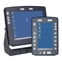
Dlog DLoG X 10 Manual (160 pages)
Brand:
Dlog
| Category:
Touch terminals
| Size: 3 MB
Table of Contents
Table of Contents
4
1 About this Manual
13
Device Version Described
13
For Qualified Personnel
13
Design Method
14
Warnings and Notices
14
Additional Design Elements
14
2 Important Safety Notices
16
Initial Operation of the Device
16
Power Supply / External Peripheral Devices
18
Repairs Only through Dlog
19
Opening and Closing the Device
19
Exchanging and Extending Modules
22
CE Marking
24
RTTE Directive 1999/5/EC
24
Special Regulations in France
24
Figure 2.1: CE Marking
24
FCC User Information
25
Interference Declaration of the Federal Communications Commission
25
Transmission of Radio Frequencies
26
3 Device Description
27
General
27
Figure 3.1: Dlog X 7, Vertical Display
27
Intended Usage
28
Figure 3.2: Dlog X 10 and Dlog X 12
28
Models
29
Abbreviations Used for Devices and Accessories
29
Device Description and Type Identification
30
Device Type Plate
30
Technical Specifications
31
System Equipment
31
Figure 3.3: Example of a Device Type Plate
31
Power Supply / Power Packs
35
AC Power Packs
37
Maximal Power Available for Peripheral Devices
38
Test Marks
39
Dimensions
40
Figure 3.4: Dimensions Dlog X 7 Front View
40
Figure 3.5: Dimensions Dlog X 7 Side View
41
Figure 3.6: Dimensions Dlog X 7 Top View
42
Figure 3.7: Dimensions Dlog X 10 Front View
43
Figure 3.8: Dimensions Dlog X 10 Side View
44
Figure 3.9: Dimensions Dlog X 10 Top View
45
Figure 3.10: Dimensions Dlog X 12 Front View
46
Figure 3.11: Dimensions Dlog X 12 Side View
47
Figure 3.12: Dimensions Dlog X 12 Top View
48
VESA Drill Holes
49
Figure 3.13: VESA Drill Holes Dlog X 7
49
Figure 3.14: VESA Drill Holes Dlog X 10
50
Figure 3.15: VESA Drill Holes Dlog X 12
51
4 Unpacking the Device
52
Scope of Delivery
52
Packaging
52
Returning Your Device
52
5 Initial Operation
53
Cooling through the Supply of Fresh Air
53
External Connectors Dlog X 7
54
Standard Connectors
54
Optional Connectors
54
Figure 5.1: External Connectors on the Dlog X 7, DC Version
54
Power Pack Models
56
Figure 5.2: External Connectors Dlog X 7, DC 12/24 V, 30 W
56
Figure 5.3: External Connectors Dlog X 7, DC 24/48 V, 30 W
56
Figure 5.4: External Connectors Dlog X 7, AC 110/230 V, 36 W
56
Figure 5.5: DC Connector (External View)
57
External Connectors Dlog X 10 and Dlog X 12
58
Standard Connectors
58
Optional Connectors
58
Power Pack Models
59
Figure 5.6: External Connectors Dlog X 12 / X 12, DC 12 V, 100 W
59
Figure 5.7: External Connectors Dlog X 12 / X 12, DC 24/48 V, 100 W
59
Figure 5.8: External Connectors Dlog X 12 / X 12, DC 24/48 V, 60 W
59
Figure 5.9: External Connectors Dlog X 12 / X 12, AC 110/230 V, 100 W
60
Connecting/Disconnecting External Devices
61
USB Connection
61
COM Connection
61
Powering up the Device
63
Removing the Protective Film from the Front
63
Protecting the TFT Display from the Memory Effect
64
Installing Application Software
64
Important Software Settings
65
Wireless Network
65
Touch Screen Calibration
65
After Extended Non-Use
66
Figure 5.10: Sliding Switch
66
6 Accessories
67
Keyboard
68
SMALL Keyboard
68
Figure 6.1: SMALL Keyboard
68
24-Key Keypad
69
Figure 6.2: 24-Key Keypad
69
Mouse
70
USB Stick
70
Scanners
70
WLAN Cards (PC Cards)
70
Compactflash
70
Adapter Cables
70
7 Mounting
71
Options for Mounting the Device
71
Observe and Retain the Mounting Instructions
71
Mechanical Dynamic Loading
72
Power Supply
72
DC Power Packs
72
AC Power Packs
73
Installing Connecting Cables
73
Vehicle Applications (such as Forklifts)
74
DC Terminals
75
Figure 7.1: Position of the Ground Bolt
75
Cable Cover (Splash Guard)
76
Protection Class IP65
76
Protection Class IP54
76
8 Operation
77
Touch Screen Operation
77
Dirty Touch Screen Surface
77
Operating Controls Dlog X 7
78
Horizontal/Vertical Versions
78
Standard Configuration (4 Keys)
78
Figure 8.1: Dlog X 7 Vertical, 4 Keys
78
Extended Configuration (17 Keys)
79
Brightness Control
79
Figure 8.2: Dlog X 7 Horizontal, 17 Keys
79
Front Controls (Standard)
80
Front Controls (Extended)
81
Operating Controls Dlog X 10 and Dlog X 12
82
Figure 8.3: Operating Controls Dlog X 10 and X 12
82
Front Controls (Standard)
83
Front Controls (Extended)
84
LED / Operating States
85
Dlog X 7
85
Dlog X 10 and Dlog X 12
85
9 Boot Loader
86
Figure 9.1: Boot Loader Diagram 1
86
Figure 9.2: Boot Loader Diagram 2
87
10 Operating System
88
11 Software Applications
89
Settings with PD.EXE
89
Configuring Backlight, Automatic Switch off and more
89
PD.EXE Dialogs Horizontally or Vertically
89
Save PD.EXE Settings
89
Launch PD.EXE
89
Figure 11.1: Symbol for Launched PD.EXE in the Task Bar
89
Menu Bar
91
Options Menu
92
Figure 11.2: Setup Dialog Box for Backlight
92
Figure 11.3: Automatic Switch off Dialog PD.EXE
95
Figure 11.4: USB-Port Configuration in PD.EXE
99
Advanced Menu
100
Info Menu
103
12 Serial Ports
104
COM1 Options
104
COM2 Options
105
RS-4Xx Operation
105
Cable Lengths and Ground Loops
106
13 Audio (Option)
107
Figure 13.1: the Audio Interface's Line Out, Line in and MIC in Sockets
107
Line in - Line out
108
MIC in - Line out
108
Circuit Diagram and Limitations
108
Figure 13.2: Audio Port Circuit Diagram
109
14 Touch Screen (Option)
110
Mouse and Keyboard Compatibility
110
Functional Description
110
Operation
110
Drivers
110
Calibration (Windows CE)
111
Resistance
112
Mechanical Resistance
112
Chemical Resistance
112
15 Internal Devices
113
PCMCIA / PC Cards (Option)
113
Heating (Option)
113
Automatic Switch off (Option)
114
Configuration with PD.EXE
114
Overview of Configuration Settings
115
16 Maintenance
116
Cleaning the Housing
116
Cleaning the Touch Screen
116
Cleaning the Cooling Fins
116
17 Common Mistakes in Usage
117
Power Supply
117
Powering Up/Powering down
117
Cable Cover
117
Mounting
118
Mobile Application on Vehicles
118
Using the Touch Screen
119
Cleaning the Device
120
Use/Storage in Extreme Temperatures
120
18 Disposal
121
19 Appendix A: Terminal Assignment (Pins)
122
External Connectors
122
Power
122
Figure 19.1: Cable Supply Voltage 24/48 VDC
122
Figure 19.2: Standard Power Plug IEC 320 Compliant
123
Signal
124
Internal Connectors Mainboard MDA2.10 05.2006
130
Figure 19.3: Internal Connectors Mainboard MDA2.10 05.2006
130
Audio Interface
137
20 Appendix B: Jumpers
139
Warning
139
Standard Jumper Settings
139
Jumper Layout View for Mainboard MDA2.10 05.2006
140
Figure 20.1: Jumper Layout, Mainboard MDA2.10 05.2006
140
COM1 Configuration
141
21 Appendix C: Mechanical Dynamic Loading
142
Introduction
142
Using the Device Without Vibration Insulation
144
Application with Passive Vibration Insulation
145
Dimensioning Example Dlog X 10
146
Figure 21.1: Table-Top Attachment with Elastomer Springs
146
Approximate Solution for the Selection of Elastomer Springs
147
Approximate Solution for Determining Insulating Effects
150
Determining Natural Frequencies
152
22 Appandix D: Tools
153
Warnings
153
Tool Kit
154
Closing the Device
154
Mounting Bracket Tool Kit
155
Figure 22.1: Mounting Bracket Tool Kit
155
23 Return Packing Slip
156
Index
157
Advertisement
Advertisement
Related Products
Dlog DLoG X 7
Dlog DLoG X 12
DLoG XMT 5/7
DLoG XMT 5/10
Dlog Categories
Touch terminals
Desktop
Tablet
Industrial PC
More Dlog Manuals
Login
Sign In
OR
Sign in with Facebook
Sign in with Google
Upload manual
Upload from disk
Upload from URL