Table of Contents
Advertisement
Quick Links
Advertisement
Table of Contents

Related Manuals for DLoG DLoG X 7

Summary of Contents for DLoG DLoG X 7
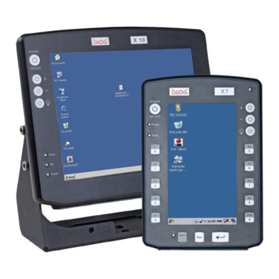
- Page 1 DLoG X 7 DLoG X 10 DLoG X 12 3.10 Manual...
- Page 2 We reserve the right to modify the contents of this document at any time and without prior notice. Because we at DLoG are constantly striving to improve this product, we cannot guarantee that previous or subsequent releases of the product will correspond in every respect with the product description given in this manual.
-
Page 4: Table Of Contents
Important safety notices................ 4 2.1. Initial operation of the device..................4 2.2. Power supply / External peripheral devices .............. 6 2.3. Repairs only through DLoG..................7 2.4. Opening and closing the device ................7 2.5. Exchanging and extending modules ............... 10 2.6. - Page 5 External connectors DLoG X 7 ................42 5.2.1. Standard connectors..................42 5.2.2. Optional connectors..................42 5.2.3. Power pack models ..................44 5.3. External connectors DLoG X 10 and DLoG X 12 ............46 5.3.1. Standard connectors..................46 5.3.2. Optional connectors..................46 5.3.3. Power pack models ..................47 5.4.
- Page 6 Operation ....................65 8.1. Touch screen operation................... 65 8.1.1. Dirty touch screen surface................65 8.2. Operating controls DLoG X 7 .................. 66 8.2.1. Horizontal/vertical versions ................66 8.2.2. Standard configuration (4 keys) ..............66 8.2.3. Extended configuration (17 keys)..............67 8.2.4.
- Page 7 8.2.5. Front controls (standard) .................68 8.2.6. Front controls (extended) ................69 8.3. Operating controls DLoG X 10 and DLoG X 12............70 8.3.1. Front controls (standard) .................71 8.3.2. Front controls (extended) ................72 8.4. LED / Operating states ....................73 8.4.1. DLoG X 7 ......................73 8.4.2.
- Page 8 Touch Screen (Option)..............98 14.1. Mouse and keyboard compatibility..............98 14.2. Functional description ..................98 14.3. Operation......................98 14.4. Drivers ......................... 98 14.5. Calibration (Windows CE) ................... 99 14.6. Resistance......................100 14.6.1. Mechanical resistance................100 14.6.2. Chemical resistance.................. 100 Internal devices ................101 15.1.
- Page 9 Introduction ......................130 21.2. Using the device without vibration insulation.............132 21.3. Application with passive vibration insulation............133 21.4. Dimensioning example DLoG X 10 ..............134 21.4.1. Approximate solution for the selection of elastomer springs.....135 21.4.2. Approximate solution for determining insulating effects......138 21.5. Determining natural frequencies................140 Appandix D: Tools ................141...
- Page 10 Figure 5.4: External connectors DLoG X 7, AC 110/230 V, 36 W........44 Figure 5.5: DC connector (external view).................45 Figure 5.6: External connectors DLoG X 12 / X 12, DC 12 V, 100 W ......47 Figure 5.7: External connectors DLoG X 12 / X 12, DC 24/48 V, 100 W ......47 Figure 5.8: External connectors DLoG X 12 / X 12, DC 24/48 V, 60 W ......47...
- Page 11 Figure 8.1: DLoG X 7 vertical, 4 keys................66 Figure 8.2: DLoG X 7 horizontal, 17 keys.................67 Figure 8.3: Operating controls DLoG X 10 and X 12............70 Figure 9.1: Boot loader diagram 1 ..................74 Figure 9.2: Boot loader diagram 2 ..................75 Figure 11.1: Symbol for launched PD.EXE in the task bar..........77...
-
Page 13: About This Manual
DLoG agent or representative. 1.1. Device version described This manual describes the models DLoG X 7, DLoG X 10, and DLoG X 12 with a board version MDA2.10 05.2006 and above. The information contained in this manual becomes applicable beginning at the time the corresponding DLoG X model is released. -
Page 14: Design Method
You must heed this information! 1.3.2. Additional design elements Lists are indicated with bullet points, for example: • DC power packs • AC power packs Instructions are numbered, for example: 1. Insert a CD. 2. Press <A>. Manual DLoG X Series... - Page 15 Any text that needs to be entered is shown in Courier font, for example: 1. Enter the text abcdefg. Other methods for emphasis Any other emphasized text elements are highlighted in bold or underlined. References to other chapters in the manual are printed in italics. DLoG X Series Manual...
-
Page 16: Important Safety Notices
Important safety notices 2. Important safety notices The DLoG X models were designed and built according to modern technology and accepted safety regulations. However, the operation of the DLoG X can endanger personnel or third parties and cause damage to the device and other material assets when for example the device is •... - Page 17 If the DLoG X device is not able to draw in fresh cooling air, this may cause overheating and severe damage to the unit. Be sure to comply with the maximum ambient temperature to guarantee correct operation (as specified in Technical specifications).
-
Page 18: Power Supply / External Peripheral Devices
Please ensure that external peripheral devices with their own power supply are switched on at the same time or after the DLoG X device. If this is not possible, please ensure that the DLoG X device is adequately protected from power leakage caused by an external device. -
Page 19: Repairs Only Through Dlog
2.4. Opening and closing the device If you choose to open the DLoG X device at your own risk, please make sure you observe the safety instructions from the previous pages. Persons authorised to open and close the device The DLoG X device may only be opened for the purposes of adding or exchanging modules. - Page 20 Make sure the cables are not unduly stressed or bent. Device seal The face of the DLoG X device has a protective seal glued into its frame. Do not attempt to remove the seal, as this will cause irreversible damage to it and render it unusable.
- Page 21 Please be aware that any test marks and the guarantee may lose their validity if the device has been improperly operated or opened/closed. For devices compliant with protection class IP65, for example, DLoG GmbH no longer guarantees the safety rating if the device has been improperly opened or closed by persons insufficiently qualified.
-
Page 22: Exchanging And Extending Modules
No battery changes The RTC of the DLoG X device is powered by a lithium battery fixed to the motherboard. This battery should not be exchanged under any circumstances, as this requires soldering! Should a lithium-battery change be necessary, the device must be sent to DLoG. - Page 23 System overload To avoid system overloads, check the total acceptable load for all of the installed components Ensure that the input power for each device is within the permitted threshold (see technical specifications for the corresponding device). DLoG X Series Manual...
-
Page 24: Ce Marking
2.7. RTTE Directive 1999/5/EC With regard to the RTTE Directive 1999/5/EC the statements in the declaration of conformity for the DLoG X device (see page 2 of this handbook) apply. 2.7.1. Special regulations in France Due to restrictions imposed by the French government, the DLoG X models with WLAN 802.11b is only permitted for use indoors. -
Page 25: Fcc User Information
In order to comply with the FCC requirements regarding radio frequency exposure from vehicle-mounted transmission devices the antenna has to be kept at least 20 cm away from people. DLoG X Series Manual... -
Page 26: Transmission Of Radio Frequencies
Do not place the DLoG X device near such devices. Keep a minimum distance of 20 cm between such a device and the DLoG X in order to reduce the risk of interference. If you have reason to assume that interference has occurred, then turn the DLoG X device off and consult a heart expert. -
Page 27: Device Description
It is designed without an external fan to lower maintenance requirements The key advantage of the DLoG X series lies in its diverse functionality and compact design. Various mounting brackets allow installation in the most confined spaces. -
Page 28: Intended Usage
Figure 3.2: DLoG X 10 and DLoG X 12 3.2. Intended usage The DLoG X 7, DLoG X 10 and DLoG X 12 devices are multifunction terminals for stationary and mobile use in commercial applications (for example logistics, storage, manufacturing, automotive). -
Page 29: Models
Any differences between the devices will be clearly noted in this manual. 3.4. Abbreviations used for devices and accessories Please note that to save space on the DLoG X device and supplied accessories, the following abbreviations have been used: Abbreviation... -
Page 30: Device Description And Type Identification
Device description 3.5. Device description and type identification 3.5.1. Device type plate The device type plate on the DLoG X series contains the following information: DLoG X 7 Describes the device with display size (7”, 10” or 12”) DLoG X 10... -
Page 31: Technical Specifications
Rugged aluminum-cast housing with integrated heat sink Hardly combustible plastic parts (acc. to UL94V-0) Protection class IP54 Upgradeable to IP65 ESD protected Weight: DLoG X 7: approx. 2,5 kg DLoG X 10: approx. 5 kg DLoG X 12: approx. 5 kg DLoG X Series Manual... - Page 32 Device description Display panel DLoG X 7: 7“ QWVGA, 400 cd/m at +20 °C, with automatic and manual brightness adjustment DLoG X 10: 10,4” SVGA, 230cd/m at +20 °C, optional 4-wire touch screen, with automatic and manual brightness adjustment bei +20 °C, 4-wire touch screen, 10,4”...
- Page 33 ESD protection, Level 3 (acc. to EN 61000-4-2) * Alternative (configured with PD.EXE) Software Microsoft Windows CE compatibility Embedded Linux on request 3.6.1.3. LCD interface Graphics Integrated in PXA 270 controller Shared memory architecture Internal plug-in connector Driver installed in Image DLoG X Series Manual...
- Page 34 1 x type 1, accessible via the side of the device 3.6.1.7. SD/SDIO interface SDIO controller Integrated in PXA 270 Driver installed in Image SDIO slot 1 x type 1, accessible via the side of the device Manual DLoG X Series...
-
Page 35: Power Supply / Power Packs
Maximum output: 100 W (9 to 16 VDC), 80 W (6 to 9 VDC) Switch off automatic (option) Heating (option) Withstands bursts up to 2 kV Primary nominal current 15 A Connection only to SELV circuit DLoG X Series Manual... - Page 36 The SELV circuit is a secondary circuit that is designed and protected in such a way 1) to 5) that its voltages will not exceed a safe value if the device is properly used or a single error occurs. Manual DLoG X Series...
-
Page 37: Ac Power Packs
Electrically-isolated Withstands bursts up to 4 kV Primary nominal current 1 A Fuse type: T1.25AL250V Rechargeable Only for DLoG X 10 and DLoG X 12: buffer battery To temporarily bridge power outages Lithium polymer rechargeable battery 11.1 V (optional) Bridging time depends on the configuration approx. -
Page 38: Maximal Power Available For Peripheral Devices
DLoG X 7: -30 °C to +50 °C (Start/Switch on temperature >= -25 °C) DLoG X 10 and X 12: 0 to +50 °C DLoG X 10 and X 12 with heating option: -30 °C to +50 °C Storage All specifications in accordance with EN 60068-2-1/2 temperature DLoG X 7: -35 °C to +65 °C... -
Page 39: Test Marks
US Highway Truck according to MIL-STD 810F: 2000 (Department of Defense), 3 hours 1 g effective noise and 600 vibrations with 20 g peaks 3.6.5. Test marks EN 55022 Class A EN 61000-3-2, EN61000-3-3, EN 61000-6-2 IEC 60950-1, EN 60950-1, UL 60950-1 DLoG X Series Manual... -
Page 40: Dimensions
Device description 3.6.6. Dimensions 3.6.6.1. Dimensions DLoG X 7 Front view Dimensions without add-ons (in mm): Figure 3.4: Dimensions DLoG X 7 front view Manual DLoG X Series... -
Page 41: Figure 3.5: Dimensions Dlog X 7 Side View
Device description Side view Dimensions without add-ons (in mm): Figure 3.5: Dimensions DLoG X 7 side view DLoG X Series Manual... -
Page 42: Figure 3.6: Dimensions Dlog X 7 Top View
Device description Top view Dimensions without add-ons (in mm): Figure 3.6: Dimensions DLoG X 7 top view Manual DLoG X Series... -
Page 43: Figure 3.7: Dimensions Dlog X 10 Front View
Device description 3.6.6.2. Dimensions DLoG X 10 Front view Dimensions without add-ons (in mm): Figure 3.7: Dimensions DLoG X 10 front view DLoG X Series Manual... -
Page 44: Figure 3.8: Dimensions Dlog X 10 Side View
Device description Side view Dimensions without add-ons (in mm): Figure 3.8: Dimensions DLoG X 10 side view Manual DLoG X Series... -
Page 45: Figure 3.9: Dimensions Dlog X 10 Top View
Device description Top view Dimensions without add-ons (in mm): Figure 3.9: Dimensions DLoG X 10 top view DLoG X Series Manual... -
Page 46: Figure 3.10: Dimensions Dlog X 12 Front View
Device description 3.6.6.3. Dimensions DLoG X 12 Front view Dimensions without add-ons (in mm): Figure 3.10: Dimensions DLoG X 12 front view Manual DLoG X Series... -
Page 47: Figure 3.11: Dimensions Dlog X 12 Side View
Device description Side view Dimensions without add-ons (in mm): Figure 3.11: Dimensions DLoG X 12 side view DLoG X Series Manual... -
Page 48: Figure 3.12: Dimensions Dlog X 12 Top View
Device description Top view Dimensions without add-ons (in mm): Figure 3.12: Dimensions DLoG X 12 top view Manual DLoG X Series... -
Page 49: Vesa Drill Holes
Device description 3.6.7. VESA drill holes 3.6.7.1. VESA drill holes DLoG X 7 This drawing indicates the DLoG X 7’s VESA drill holes: Figure 3.13: VESA drill holes DLoG X 7 DLoG X Series Manual... -
Page 50: Figure 3.14: Vesa Drill Holes Dlog X 10
Device description 3.6.7.2. VESA drill holes DLoG X 10 This drawing indicates the DLoG X 10’s VESA drill holes: Figure 3.14: VESA drill holes DLoG X 10 Manual DLoG X Series... -
Page 51: Figure 3.15: Vesa Drill Holes Dlog X 12
Device description 3.6.7.3. VESA drill holes DLoG X 12 This drawing indicates the DLoG X 12’s VESA drill holes: Figure 3.15: VESA drill holes DLoG X 12 DLoG X Series Manual... -
Page 52: Unpacking The Device
4. Unpacking the device 4.1. Scope of delivery The delivery includes at least the following components: • The ordered DLoG X model • The ordered assembly set (if ordered) • One cable cover (standard = IP54; optional = IP65) • One connecting cable for DC connection •... -
Page 53: Initial Operation
Never install the system in a closed environment where the cooling air is unable to dissipate accumulated heat to the outside. If the DLoG X device is not able to draw in fresh cooling air, this may cause overheating and severe damage to the unit. -
Page 54: External Connectors Dlog X 7
Fuse holder USB Host USB Client Slide switch COM1 COM2 USB Host Figure 5.1: External connectors on the DLoG X 7, DC version 5.2.2. Optional connectors Read more about the optional connectors in the following sections: 12.2 Manual DLoG X Series... - Page 55 Initial operation COM2 Options 13 Audio (Option) DLoG X Series Manual...
-
Page 56: Power Pack Models
Initial operation 5.2.3. Power pack models Figure 5.2: External connectors DLoG X 7, DC 12/24 V, 30 W Figure 5.3: External connectors DLoG X 7, DC 24/48 V, 30 W Figure 5.4: External connectors DLoG X 7, AC 110/230 V, 36 W... -
Page 57: Figure 5.5: Dc Connector (External View)
Explanation: Ignition on means that a control signal has to be routed to this connection (e.g., ignition of a vehicle) that matches the supply voltage level and can supply at least 2 W. The signal reference is DC-. DLoG X Series Manual... -
Page 58: External Connectors Dlog X 10 And Dlog X 12
Initial operation 5.3. External connectors DLoG X 10 and DLoG X 12 5.3.1. Standard connectors The standard connectors correspond to the External connectors DLoG X 7. 5.3.2. Optional connectors Read more about the optional connectors in the following sections: 12.2... -
Page 59: Power Pack Models
13 Audio (Option) 5.3.3. Power pack models Figure 5.6: External connectors DLoG X 12 / X 12, DC 12 V, 100 W Figure 5.7: External connectors DLoG X 12 / X 12, DC 24/48 V, 100 W Figure 5.8: External connectors DLoG X 12 / X 12, DC 24/48 V, 60 W... -
Page 60: Figure 5.9: External Connectors Dlog X 12 / X 12, Ac 110/230 V, 100 W
Initial operation Figure 5.9: External connectors DLoG X 12 / X 12, AC 110/230 V, 100 W Manual DLoG X Series... -
Page 61: Connecting/Disconnecting External Devices
No other specific precautions are required for the DLoG X devices. 5.4.2. COM connection Before connecting or disconnecting devices to a COM port on the DLoG X device, you must first disconnect the DLoG X device from the power supply. - Page 62 Initial operation Always shut down the DLoG X device as follows: 1. If your DLoG X device has automatic switch off, shut down the device using the ignition input. 2. If your device has an activated <Power> button, shut it down using this button.
-
Page 63: Powering Up The Device
5.6. Removing the protective film from the front The front of the DLoG X device is protected during transport by a transparent film. This film should remain on the front during assembly to avoid damage to the front surface. -
Page 64: Protecting The Tft Display From The Memory Effect
5.7. Protecting the TFT display from the memory effect The TFT display of the DLoG X device has to be protected from the burning in of a motionless image. An image that has remained motionless for too long can cause irreversible damage to the display. -
Page 65: Important Software Settings
5.9. Important Software Settings 5.9.1. Wireless network Depending on the optional equipment and specific use of the DLoG X device, settings/access data must be defined for wireless networks such as WLAN. For information on WLAN settings, refer to online help for the menu Start | Settings | Network Dial-Up Connections. -
Page 66: After Extended Non-Use
Initial operation 5.10. After extended non-use The DLoG X device is delivered with the RTC battery switched off by default. The RTC battery powers the clock in the event of power failure (power reserve). The RTC battery is switched on and off by means of a sliding switch located at the bottom right of the DLoG X device connector bay. -
Page 67: Accessories
• Scanner • WLAN Cards • CompactFlash • Adapter cable Use only accessories for the DLoG X-series that have been tested and approved by DLoG GmbH. You can find out about approved items from your DLoG sales office. DLoG X Series... -
Page 68: Keyboard
Accessories 6.1. Keyboard You can connect a USB keyboard to the DLoG X device with a USB-A or USB Mini-A connector. 6.1.1. SMALL keyboard A mountable SMALL keyboard (German/English; protection class IP 65) is available for the DLoG X series. -
Page 69: 24-Key Keypad
For the DLoG X 7, this keyboard is only available for a device with a vertical display. The keyboard is not made to be used with a horizontal display. For the DLoG X 10 and X 12, at he 24-key keyboard can be attached to the right side of the device. -
Page 70: Mouse
Accessories 6.2. Mouse You can connect a USB mouse to the DLoG X device using a USB-A or USB Mini-A connector. The system only supports two mouse buttons. 6.3. USB Stick You can connect a USB stick to the DLoG X device with a USB-A or USB Mini-A connector. -
Page 71: Mounting
Depending on the vibration resistance and pivoting demands, mounting brackets, clamp foots or RAM mount elements can also be used to attach the device. Please contact your DLoG sales office to find out more about the whole range of installation options on offer. -
Page 72: Mechanical Dynamic Loading
Mounting 7.3. Mechanical dynamic loading Since the DLoG X device is a weighted structure, it is invariable that the unit will be subject to mechanical dynamic effects. Therefore optimizing the mounting can be very helpful. Please refer to Appendix C: Mechanical dynamic loading. -
Page 73: Ac Power Packs
Ensure that the disconnecting device isolates all supply voltage lines. 7.4.3. Installing connecting cables Ue the connecting cables supplied to connect the DLoG X device to the power supply. Make sure that the connecting cables are laid without kinks and are protected. DLoG X Series... -
Page 74: Vehicle Applications (Such As Forklifts)
7.5. Vehicle applications (such as forklifts) Pay special attention to the various electrical potentials when installing the unit on a vehicle (such as a forklift). In the DLoG X devices, the logic ground and the shield ground are firmly linked. -
Page 75: Dc Terminals
• If you want to connect devices fed by other power sources to the DLoG X device (e.g. certain printers), make sure to power up the peripheral devices at the same time or after the DLoG X device. -
Page 76: Cable Cover (Splash Guard)
7.6.2. Protection class IP54 To ensure that the DLoG X devices continues to conform to this protection category, proceed as follows: 1. Place the cables connected to and from the device next to each other. Avoid crossing the cables. -
Page 77: Operation
8. Operation 8.1. Touch screen operation All DLoG X devices are available with the option of a resistive touch screen. The touch screen surface should be kept free of dirt, sand, stones, and similar materials, in order to prevent damage. -
Page 78: Operating Controls Dlog X 7
Operation 8.2. Operating controls DLoG X 7 There are a number of indicator lamps and controls on the front of the DLoG X 7. Available models: • Standard configuration with 4 keys • Extended configuration with 17 keys 8.2.1. Horizontal/vertical versions The DLoG X 7 is available in two versions for either horizontal or vertical mounting. -
Page 79: Extended Configuration (17 Keys)
Note for units featuring brightness control: Even after manually turning off the display lighting, the DLoG X 7 will continue to respond to input via the keyboard, mouse or touch panel. This means that you can continue to enter commands and data even if the display lighting is off. -
Page 80: Front Controls (Standard)
Operation 8.2.5. Front controls (standard) Indicator/control Explanation <Power> button to switch the DLoG X 7 on/off: This button has been preconfigured by DLoG to provide the following functions by default: DLoG X 7 <Power> button is not used for powering up with automatic the unit. -
Page 81: Front Controls (Extended)
8.2.6. Front controls (extended) Indicator/control Explanation These buttons have two functions: • 0 to 9 • When the <Shift>-key is held: Function keys <F1> to <F10> <Enter> key <Esc> key <Shift> key Status indicator of the <Shift> key DLoG X Series Manual... -
Page 82: Operating Controls Dlog X 10 And Dlog X 12
8.3. Operating controls DLoG X 10 and DLoG X 12 There are a number of indicator lamps and controls on the front of the DLoG X 10 and DLoG X 12. The standard model has only four buttons and three indicator lamps on the left-hand side (picture in the foreground). -
Page 83: Front Controls (Standard)
Operation 8.3.1. Front controls (standard) Indicator/control Explanation <Power> button to switch the DLoG X 10 / 12 on/off: This button has been preconfigured by DLoG to provide the following functions by default: DLoG X 10 / DLoG X 12 with <Power>... -
Page 84: Front Controls (Extended)
/PgDn “Cursor Down” or “PageDown” when pressing the <Shift> key /Home “Cursor Left” or all the way left on that line when pressing the <Shift> key /End “Cursor Right” or all the way right on that line when pressing the <Shift> key Manual DLoG X Series... -
Page 85: Led / Operating States
Computer is starting up; normal operational state; shutdown delay time is running Temp. < -30 °C or temp. > 50 °C Temperature sensor is malfunctioning FLASHING 8.4.2. DLoG X 10 and DLoG X 12 Status of internal LEDs Device status Power (green) Temp (red) -
Page 86: Boot Loader
The DLoG X bootloader initializes, configures and tests the hardware according to the settings. The operating system will then load. The Windows CE 5.0 bootloader used in the DLoG X models is based on EBoot from Microsoft. The bootloader and operating system are described in greater detail in the Windows CE technical manual. -
Page 87: Figure 9.2: Boot Loader Diagram 2
Boot loader Figure 9.2: Boot loader diagram 2 DLoG X Series Manual... -
Page 88: Operating System
Operating system 10. Operating system The DLoG X devices are available with the Windows CE 5.0 or, if requested, Embedded Linux operating system. The operating system you order is pre-installed at the factory. The operating system pre-installed on the DLoG X device is loaded following the bootloader system messages. -
Page 89: Software Applications
11.1. Settings with PD.EXE 11.1.1. Configuring backlight, automatic switch off and more The PD.EXE software is used to adjust important settings for the DLoG X models with Windows CE such as backlighting, automatic switch off and in some cases the front keyboard assignment. - Page 90 Software applications 11.1.4.1. Automatical start The DLoG X device is generally configured at the factory so that the PD software launches automatically when starting up the computer. Programs to be automatically started are found under Windows | Startup. 11.1.4.2. Manual start A manual start may be required if the PD program has been closed by clicking on the Advanced | Exit menu option.
-
Page 91: Menu Bar
If some of the options in the menu bar are grayed out, then you may not have the necessary permission to modify these settings. Further information can be found in chapter Advanced | Set User Permissions. DLoG X Series Manual... -
Page 92: Options Menu
The Options menu contains the following functions: • Backlight • Set Front Keys • Switch Off • USB-Port Config • Remote Control 11.1.6.1. Backlight Clicking the Backlight function will result in the following dialog box: Figure 11.2: Setup dialog box for backlight Manual DLoG X Series... - Page 93 Auto Brightness Please note: Auto brightness control is only available on by key the DLoG X 7 device! Press and hold the backlight key for approx. 3 seconds to toggle between automatic and manual brightness control. You can set the brightness manually using +/- Front keys or Fixed.
- Page 94 Software applications 11.1.6.2. Set Front Keys Using Set Front Keys you can assign the front keys on the DLoG X with particular commands or with program activation. When the function opens up, an interactive graphic appears with all available keys on the DLoG X device.
-
Page 95: Figure 11.3: Automatic Switch Off Dialog Pd.exe
Virtual key code names can be obtained, for example, from the Microsoft MSDN website (Microsoft Developer Network). 11.1.6.3. Automatic switch off This option allows you to configure the automatic switch off for DLoG X devices. Figure 11.3: Automatic switch off Dialog PD.EXE Automatic switch off You can only implement this setting if you have purchased the automatic switch off option. - Page 96 Power Key Functions Power Key enabled Enables or disables the power key on the front of the device If the key is disabled, you cannot use it to switch the power supply on or off. Manual DLoG X Series...
- Page 97 Do NOT select Power key or Ignition or Power key + Ignition if an ignition cable has not been connected. If you select one of these settings and an ignition cable has not been connected, the DLoG X terminal will no longer start.
- Page 98 DLoG X terminal will shut down after the delay time expires. Always On The DLoG X switches off as soon as it is no longer supplied with power. Ignition Switching off the ignition activates the automatic switch off function.
-
Page 99: Figure 11.4: Usb-Port Configuration In Pd.exe
The USB host is non-recurring and is only active until the next computer start. Then the USB client automatically becomes active again. 11.1.6.5. Remote Control This function was not yet been implemented upon publication of the manual. DLoG X Series Manual... -
Page 100: Advanced Menu
The program launches in the User mode by default. This is indicated by the black check symbol in the task bar. You can modify the user permissions in the Administrator or Service mode. The Service password is intended for DLoG support only. Enter Password Admin You must enter the Administrator password here . - Page 101 2. Click OK to close the dialog box. The password is then changed. If the password fields are cleared, this indicates that the entries were not identical. Re-enter the password. 11.1.7.2. Change EE-Data This option is ONLY available to DLoG technical support. Incorrect settings may damage the hardware. DLoG X Series Manual...
- Page 102 Enter the name of the new image file (e.g. org2.hex) in the text field under Image File and click Start Update. Be sure to only use DLoG images. The use of incorrect software may damage the hardware. 11.1.7.4. Set User Permissions This menu option allows you to set the user permissions for the PD software.
-
Page 103: Info Menu
System Info • save system specific files in a textfile with Make Report (only for DLoG service!) 11.1.8.1. About If you click the About menu option, the system will display a small dialog box with the software version and DLoG GmbH copyright. -
Page 104: Serial Ports
Serial ports 12. Serial ports The DLoG X devices have two serial ports RS-232. 12.1. COM1 Options COM1 comes with a “full function” UART. All of the pins are reserved and can be used. If using the COM1 port to power external devices, please note the following: •... -
Page 105: Com2 Options
COM2 comes with a standard UART. The pins TxD, RxD, CTS, RTS are reserved and can be used. The RS-422/485 function is only available with a special adapter plate. This can be ordered from your DLoG sales agent. 12.2.1. RS-4xx operation This operating mode is not supported by any of the available operating systems. -
Page 106: Cable Lengths And Ground Loops
These compensation currents, which are also present at the ground point of the RS-232 connection, may significantly degrade signal quality and effectively stop the data flow. In challenging environments, electrically-isolated connections (via external converters) or differential systems (RS-422/485 standard) are strongly recommended. Manual DLoG X Series... -
Page 107: Audio (Option)
Audio (Option) 13. Audio (Option) The audio option for DLoG X devices provides two connection sockets for connecting a microphone, inputting audio data into a device or connecting speakers, for example. Two different audio options are available: • Line In and Line Out •... -
Page 108: Line In - Line Out
• Connect speakers (Line Out); Line Out is usually executed in stereo. 13.2.1. Circuit Diagram and Limitations The audio option is only suitable for electret microphones. The following circuit diagram shows this limitation in more detail. Manual DLoG X Series... -
Page 109: Figure 13.2: Audio Port Circuit Diagram
Audio (Option) Figure 13.2: Audio port circuit diagram DLoG X Series Manual... -
Page 110: Touch Screen (Option)
14.1. Mouse and keyboard compatibility Touch screens on the DLoG X-series can be operated with or without a keyboard and are also compatible with a mouse. 14.2. Functional description A touch screen controller is integrated into the mainboard to analyze the resistance changes caused by touch. -
Page 111: Calibration (Windows Ce)
14.5. Calibration (Windows CE) The touch screen must be calibrated before use: 1. To do this, start the DLoG X device and wait briefly until the operating system has launched fully. 2. Press the touch screen until a shortcut menu appears (functions like a right mouse button). -
Page 112: Resistance
14.6.1. Mechanical resistance Pencil hardness test ASTM D 3363-92a The resistive DLoG touch screens have a hardness ≥ 4 H. Test scale (from softest to hardest): 6 B, 5 B, 4 B, 3 B, 2 B, B, HB, F, H, 2 H, 3 H, 4 H, 5 H, 6 H, 7 H, 8 H, 9 H 14.6.2. -
Page 113: Internal Devices
15.1. PCMCIA / PC cards (Option) Only use PCMCIA cards on your DLoG X device that have been tested and approved by DLoG. You can find out about approved equipment from your DLoG sales office. The drivers for the PCMCIA cards must be included in the image. -
Page 114: Automatic Switch Off (Option)
Internal devices 15.3. Automatic switch off (Option) Devices in the DLoG X Series can be optionally equipped with an automatic switch off. 15.3.1. Configuration with PD.EXE The PD.EXE program is installed in the Windows CE Image and allows you to configure the automatic switch off. -
Page 115: Overview Of Configuration Settings
• PD.EXE generates a system message similar to WM_QUERYENDSESSION • Applications have the switch off time at their disposal in which to end all currently running processes DLoG X Series Manual... -
Page 116: Maintenance
Do not use sulfurous agents. 16.3. Cleaning the cooling fins To prevent a build-up of heat in the DLoG X device, the cooling fins must remain free of dirt and dust. For best results, clean the cooling fins with a soft brush. -
Page 117: Common Mistakes In Usage
• Be sure to observe the correct polarity of the connection cables. • Devices in the DLoG X Series that have an AC power pack should only be connected to TN and TT networks. IT networks are not permitted as dangerous electric shocks cannot be ruled out here. -
Page 118: Mounting
• The top cover hood of the wireless card serves to protect the card. Do not use it as a handle when turning, holding or lifting the terminal. • All fastening bows and mounting parts supplied by DLoG are only intended for use in the mounting of terminals and peripheral devices and may not be used for other purposes. -
Page 119: Using The Touch Screen
• Please be aware that, for example, on forklifts with inverter drives, malfunctions can occur in the power supply that are beyond the potential tolerance of the DLoG X device. In such cases the DLoG X device can be irreparably damaged. In such circumstances it may be necessary to install a line filter. -
Page 120: Cleaning The Device
Do not use sulfurous agents. • To prevent a build-up of heat in the DLoG X device, the cooling fins must remain free of dirt and dust. For best results, clean the cooling fins with a soft brush. Do not use compressed air or a vacuum cleaner, as this can damage the surface. -
Page 121: Disposal
Disposal 18. Disposal The DLoG GmbH general terms and conditions set out the obligations for disposal in accordance with official electronics regulations. DLoG X Series Manual... -
Page 122: Appendix A: Terminal Assignment (Pins)
Appendix A: Terminal assignment (Pins) 19. Appendix A: Terminal assignment (Pins) 19.1. External connectors 19.1.1. Power 19.1.1.1. DC voltage supply cable The following diagram shows the DC device’s supply connection cables. Figure 19.1: Cable supply voltage 24/48 VDC Manual DLoG X Series... -
Page 123: Figure 19.2: Standard Power Plug Iec 320 Compliant
Appendix A: Terminal assignment (Pins) 19.1.1.2. AC voltage supply connector Standard power plug (IEC 320 compliant) Figure 19.2: Standard power plug IEC 320 compliant DLoG X Series Manual... -
Page 124: Signal
Version: 4pol. USB A, Mainboard ref. P18 Signal +5V, 500mA fused USB Host 2 Version 5pol. USB A Mini, Mainboard ref. P19 Signal VBUS USB Client Version 5pol. USB B Mini, Mainboard ref. P17 Signal VBUS Manual DLoG X Series... - Page 125 Via adapter cable to mainboard ref. P16 RS-232 version (Standard) Signal Name n.c. Not connected Receive Data Transmit Data n.c. Not connected Signal Ground n.c. Not connected Request to Send Clear to Send n.c. Not connected DLoG X Series Manual...
- Page 126 Receive Data + TXD+ Transmit Data + RS-485 version (optional) Signal Name Connected to Pin2 Connected to Pin1 not connected Receive/Transmit Data − RXD-/TXD− Signal Ground Connected to Pin7 Connected to Pin6 not connected RXD+/TXD+ Receive/Transmit Data + Manual DLoG X Series...
- Page 127 Appendix A: Terminal assignment (Pins) PC Card Mainboard ref. P4 Signal Pin-Nr. Signal /CE1 RDY/BSY WP/IOIS16 /CD1 /CE2 VSS1 /IORD /IOWR DLoG X Series Manual...
- Page 128 Appendix A: Terminal assignment (Pins) VSS2 RESET /WAIT /INPACK /REG BVD2 BVD1 /CD2 SD/SDIO Version: Reverse SD/SDIO – Socket, Mainboard ref. P6 Signal DATA3 VDD 3V CLOCK DATA0 DATA1 DATA2 Manual DLoG X Series...
- Page 129 Appendix A: Terminal assignment (Pins) CompactFlash plug-in connector Version: 2-row pin base, 50-pin, Mainboard ref. P3 Signal Signal /CE1 VCC0 WP/IOIS16 /CE2 /VS1 /IORD /IOWR READY/IREQ VCC1 /CSEL /VS2 RESET /WAIT /INPACK /REG BVD2/SPKR BVD1/STSCHG n.c. = not connected DLoG X Series Manual...
-
Page 130: Internal Connectors Mainboard Mda2.10 05.2006
Appendix A: Terminal assignment (Pins) 19.2. Internal connectors mainboard MDA2.10 05.2006 Overview: P6 P3 P14 P16 P18 P19 Figure 19.3: Internal connectors mainboard MDA2.10 05.2006 Manual DLoG X Series... - Page 131 ED10 ED11 ED12 ED13 ED14 ED15 ED16 ED17 ED18 ED19 ED20 ED21 ED22 ED23 ED24 ED25 ED26 ED27 ED28 ED29 ED30 ED31 EA24 EA25 EA23 EA22 EA21 EA20 EA19 EA18 EA17 EA16 EA15 EA14 EA13 EA12 DLoG X Series Manual...
- Page 132 JTAG TCK JTAG TDO /SX_POE /SX_PWE PRD/WR JTAG ENA /PCS2 /PCS4 /PCS0 /PCS1 MBREQ MBGNT /EXP_SL_CS0 /EXP_SL_CS1 /EXP_SL_CS2 /SRST JTAG_PROG /JRST VCCORE EXP_SL_ID0 EXP_SL_ID1 EXP_SL_ID2 EXP_SL_ID3 n.c. n.c. n.c. n.c. n.c. USIM_VS0 USIM_VS2 ABUS3 VCC5.0 ABUS2 GPIO86 Manual DLoG X Series...
- Page 133 GPIO101 GPIO102 GPIO41 GPIO0 GPIO84 GPIO12 USB_EXT /PIC_RESET COM3_TXD COM3_RXD COM2_TXD COM2_RXD COM2_RTS COM2_CTS COM1_CTS COM1_RXD COM1_DSR COM1_DCD COM1_TXD COM1_RI COM1_RTS COM1_DTR I/O_PIC3 I/O_PIC2 VP12 VP12 VP12 VP12 GSM_ALARM VBAT SDA1 SCL1 SDA0_3.3 SCL0_3.3 AIN1 I/O_PIC1 DLoG X Series Manual...
- Page 134 VP12_SW VP12_SW VCC5.0 VCC5.0 VCC3.3_SW VCC3.3_SW Heating Version: AMP module, 2-pin, Mainboard ref. P23 (and P22 only for DLoG X 10 and X 12) Signal Reset Version: 1-row pin strip, 2-pin, Mainboard ref. P2 Signal /RESET Manual DLoG X Series...
- Page 135 Appendix A: Terminal assignment (Pins) SDIO Version: Molex 52610-10 1-row, 10-pin, Mainboard ref. P5 Signal VCC_SDIO VCC_SDIO DATA0 DATA1 DATA2 DATA3 JTAG Version: Hirose DF13 1-row, 8-pin, Mainboard ref. P8 Signal /SRST /JRST +3,3 V DLoG X Series Manual...
- Page 136 Version: 1-row pin strip, 3.96 mm grid, 4-pin, Mainboard ref. P1 Signal +12 V +12 V Ignition signal connector Version: Hirose DF13, 10-pin, 2-row, Mainboard ref. P24 Pin-Nr. Signal Zündungssignal DC-IN-GND n. c. n. c. SUPPLY-LOW-POWER +12 V_STANDBY Manual DLoG X Series...
-
Page 137: Audio Interface
+5 V fused 19.2.1. Audio interface Version: Hirose DF13, 12-pin, Mainboard ref. P10 Signal LINE IN R LINE IN L LINE OUT R LINE OUT L +5 V +5 V +12 V AGND AGND SDA (I SCL (I DLoG X Series Manual... - Page 138 Signal Signal VCC3.3_SW VDIMM VCC_PIC VP12_SWS VCC5.0_LCD VP12_SWS VCC3.3_LCD SWITCH0 LV_Y3P SWITCH1 LV_Y3M SWITCH2 SWITCH3 LV_CLP SWITCH4 LV_CLM SWITCH5 LV_Y2P BKLPWM5.0 LV_Y2M BKLEN TEMPLED_CON LV_Y1P SHIFTLED_CON LV_Y1M BSENSE LV_Y0P VCC5.0 LV_Y0M Manual DLoG X Series...
-
Page 139: Appendix B: Jumpers
Changing the jumper positions can impair the function of the DLoG X device or destroy the unit! if the jumper settings are changed, DLoG GmbH is no longer liable for warranty claims! 20.2. Standard jumper settings The default jumper settings are marked “... -
Page 140: Jumper Layout View For Mainboard Mda2.10 05.2006
Appendix B: Jumpers 20.3. Jumper layout view for mainboard MDA2.10 05.2006 Figure 20.1: Jumper layout, Mainboard MDA2.10 05.2006 Manual DLoG X Series... -
Page 141: Com1 Configuration
Version: 2-row pin strip, 2.00 mm grid, 6-pin, Mainboard ref. P15 Jumper Function Pin9 is RI* not required* *) Factory setting Jumper Function Pin9 is voltage supply +5 V on Pin9 Jumper Function Pin9 is voltage supply +12 V on Pin9 DLoG X Series Manual... -
Page 142: Appendix C: Mechanical Dynamic Loading
21. Appendix C: Mechanical dynamic loading 21.1. Introduction The mechanical environmental conditions of the DLoG X 7, DLoG X 10 and DLoG X 12 can vary greatly in terms of vibrations, collisions and shocks. The matter is made more difficult by the fact that the random values for acceleration and their frequencies for a given location are often unknown. - Page 143 Operational environments with low energy vibrations and medium energy shocks as well as very careful handling / transport compliant with: • Operation class 5M1 according to DIN EN 60721-3-5. • Examples: Vehicles with very good shock absorption: car dashboard, immobile mounting surfaces: desk or wall. DLoG X Series Manual...
-
Page 144: Using The Device Without Vibration Insulation
For an initial assessment, you can test the device by hand. Bring the system to excitation by gently hitting it with your hand. If the DLoG X device vibrates noticably and for an extended period, then the natural frequencyis probably too low. In this case, we recommend reinforcing the fixing points to the maximum bending moment (through the use of rigid sections, for example). -
Page 145: Application With Passive Vibration Insulation
This is practically impossible, if you consider that excitation accelerations within the range of around 10 Hz to 200 Hz or more may occur. Furthermore, the springs of the DLoG X device would strongly deflect while static or visibly swivel while resonating (blurred display). -
Page 146: Dimensioning Example Dlog X 10
What insulating effects can be expected for different excitation frequencies? Mounting example for table-top attachment with elastomer springs: • DLoG X 10 with mobile mounting bracket, Pivots up to 100 degrees • Total oscillatory mass DLoG X 10: approx. 5 kg •... -
Page 147: Approximate Solution For The Selection Of Elastomer Springs
78 N/mm / 4 = 19.5 N/mm. Of the six degrees of freedom in which the DLoG X 10 can oscillate, we only consider those with the greatest deflection for the sake of simplicity. In other words, we observe the display as it oscillates towards or away from us (a combination of rotational and longitudinal oscillation). - Page 148 This theoretical value of 16.9 Hz lies on the boundary of the natural frequencies of 20 Hz ± 5 Hz as measured in practice The calculations depicted above are only approximations and thus we recommend a final field test with the selected elastomer springs. Manual DLoG X Series...
- Page 149 Appendix C: Mechanical dynamic loading 21.4.1.1. Further possible steps for optimization If it turns out that the DLoG X 7’s, DLoG X 10’s DLoG X 12’s resonance deflections could be greater, the natural frequency can be reduced. In our selected example, softer elastomer springs with the same design could be used.
-
Page 150: Approximate Solution For Determining Insulating Effects
Consequently, the amplitude of the reaction accelerations of the DLoG X 10 / X 12 still only reaches 67% of the amplitude of the excitation accelerations, which actually have an effect twice that of the natural frequency. - Page 151 • If high energy excitation frequencies mainly occur at or below the natural frequency of the DLoG X 10 or X 12 with its mounting, then you should not use a spring mounting. High energy excitation frequencies at or below the natural frequency can be found, for example, in a vehicle chassis tuned to a low frequency.
-
Page 152: Determining Natural Frequencies
= deflection of the center of gravity in the direction of the gravitational force (for example using a mechanical timer) Further technical information can be found in the product documents provided by the elastomer spring manufacturers. Manual DLoG X Series... -
Page 153: Appandix D: Tools
Also be sure to read the warnings and notices from chapter 2.4 Opening and closing the device. The DLoG X devices may only be opened for the purposes of adding or exchanging modules. Only qualified personnel or persons trained by DLoG are authorised to do this. -
Page 154: Tool Kit
Appandix D: Tools 22.2. Tool kit The tools listed below are required to assemble/disassemble the DLoG X devices. • 3-mm hexagonal screwdriver • Phillips screwdriver, size 1 • Screwdriver, size 2 • Screwdriver, size 4 • Socket wrench, size 5 mm •... -
Page 155: Mounting Bracket Tool Kit
Appandix D: Tools 22.3. Mounting bracket tool kit The tools shown in the figure below are required to adjust the DLoG X mounting bracket: • A 5 mm / 6 mm hexagonal socket wrench (allen key) for mounting and adjusting the Fixed Mounting Bracket. -
Page 156: Return Packing Slip
[ ] Unit was already damaged on delivery (please enclose a copy of the delivery note) [ ] Delivery was incomplete Missing parts: [ ] The following error occurs when operating the unit: [ ] Separate error report is enclosed Manual DLoG X Series... -
Page 157: Index
Device type plate ............18 Calibration ..............97 Dimensions ..............28 Category US Highway Truck........128 DIN EN 60721-3-5 ..........128, 129 CE ................. 27 DIN EN 60721-3-5:1997 ..........128 CE Marking ..............12 Disconnecting device .............49 Centre of gravity............133 Disconnector ..............5 DLoG X Series Manual... - Page 158 Module extension ............10 Ignition connecting cables ..........58 Moisture................8 Ignition signal............71, 82 Motherboard ..............11 Ignition signal connector..........122 Mounting..............57, 104 Image file ...............88 Mounting bracket........... 57, 131 Image quality deterioration ..........102 Mounting bracket tool kit ..........141 Manual DLoG X Series...
- Page 159 Primary nominal current ..........25 Special key..............70 Protection class IP65 ........8, 9, 62, 103 Special regulations in France.........12 Protective film from the front ......... 49 Splash guard............20, 62 PXA 270 ................ 20 Start-up problems ............61 DLoG X Series Manual...
- Page 160 USB mouse ..............56 USB port configuration ..........85 USB stick ...............56 User mode ...............86, 88 User permissions for PD software .........88 Validity of test marks ............9 Vehicle applications............60 Vehicle chassis............137 VESA drill holes.............37 Vibration ................27 Vibration insulation ............130 Manual DLoG X Series...
Need help?
Do you have a question about the DLoG X 7 and is the answer not in the manual?
Questions and answers