Sign In
Upload
Manuals
Brands
Digital Equipment Manuals
Computer Hardware
PDT 11/150
Digital Equipment PDT 11/150 Manuals
Manuals and User Guides for Digital Equipment PDT 11/150. We have
2
Digital Equipment PDT 11/150 manuals available for free PDF download: Technical Manual, User Manual
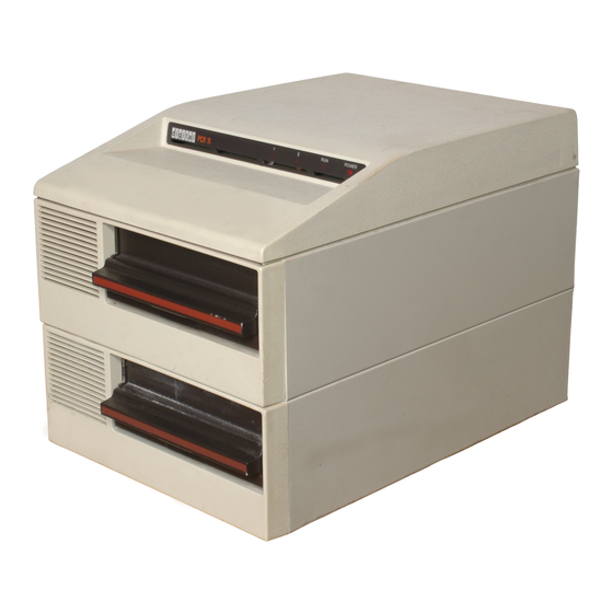
Digital Equipment PDT 11/150 Technical Manual (324 pages)
Brand:
Digital Equipment
| Category:
Computer Hardware
| Size: 12 MB
Table of Contents
Table of Contents
4
Preface
16
Chapter 1 Introduction
18
Typical System Configurations
18
Equipment and Media Specifications
21
Related Publications
21
Ordering Information for DIGITAL Personnel
25
Ordering Information for Customers
25
Technical Reference Material
26
Chapter 2 Unpacking/Installation
30
Unpacking and Inspection
30
Site Preparation and Connections
32
AC Power Requirements
32
Serial Line Cable Connectors
34
EIA Connector Pin Assignments
34
Serial Line Cable Lengths
34
Serial Line Data Characteristics
34
Chapter 3 Operating Procedures
39
Switches and Indicators
39
Front Panel Indicators
39
Rear Panel Switches and Components
39
Function Switch
40
Disk Handling and Storage
42
Test Procedures
42
Preliminary Setup
44
Optional Loopback Connector
44
Self-Test Procedures
45
Loading a System Program
46
Changing a System Program
47
Chapter 4 Technical Description
48
General Operation
48
Intelligence Module (KDT 11)
48
RAM Module (Mstll)
50
Peripheral Module (Dltll)
50
Standard and Cluster EIA Modules (Dftll)
50
Disk Controller Module (Rxtl1)
50
Power Supply Assembly (H7833)
50
PDT-Ll/150 BUS STRUCTURE
51
Signal Distribution
55
System Operation
55
Power-Up Functions
55
I/O Microprocessor Control
57
Data Transfer Operations
57
LSI-II Resident Memory
58
Peripheral Device Interface
58
EIA/TTL Level Converters
59
Disk Controller
59
Intelligence Module Functions (Dwg. No. 5413271)
59
Test Indicator Register
65
8085 Memory and I/O Select Address Decoding
65
Power-Up and Manual Reset
68
Inter-Processor Link (IPL) and Control Logic
70
LSI-II Microprocessor and Associated Logic
70
Clock Pulse Generator and Power Inverter
74
LSI-II I/O Transfer Sequence
75
LSI-II I/O Device Address Decoding
80
Function Control, Fast DIN and Interrupt Request Logic
84
Ram Module Functions (Dwg. No. 5413275)
87
RAM Module, Simplified Function Diagram
88
RAM Matrix Configurations
90
RAM Module, Memory Matrix Configurations
90
Address Bus Distribution
91
Bank Select Decoder Logic
91
Memory Address Word Formats
92
Row /Column and Address Multiplexer, Control Logic
94
Row /Column and Address Multiplexer, Timing Diagram
96
RAM Refresh Logic
97
RAM Read or Write Operations
97
Reply Logic
97
Peripheral Module Functions (Dwg. No. 5413269)
98
Information Transfers
98
Peripheral Module, Simplified Function Diagram
99
Standard Device Usarts
100
Optional Device Usarts
104
Front Panel Indicators
105
Front Panel Indicator Logic, Simplified Diagram
105
Function Switch Selections
106
Standardeia Module Functions (DWG. NO. 5413267)
107
Standard EIA Module, Simplified Diagram
110
Cluster EIA Module Functions (DWG. NO. 5413427)
111
Flexible Disk Description
113
Flexible Disk and Envelope
113
Recording Format
114
Header Field
114
Data Field
114
Flexible Disk, Track and Sector Information
114
Recording Method
115
Data Recording Patterns
115
Data and Address Mark Recording
115
Double Frequency (FM) Data Recording Pattern
116
Double Frequency (FM) Address Mark Pattern
116
Disk Controller Module Functions (Dwg. No. 5413273)
117
8085 Controller Microprocessor
117
Disk Controller Module, Simplified Function Diagram
118
Power-Up and Initialize Functions
120
Read or Write Operations
121
Disk Drive Selections
121
Self-Test Function Select and Indicator Logic
122
Self-Test Function Select and Display, Simplified Diagram
122
Head Load Control and Track/Index Hole Detection
123
Head Load Control and Track and Index Hole Detection
124
Stepper Motor Direction and Control Logic
126
Stepper Motor Pulse Generation
126
Step Generator Circuit, Simplified Diagram
127
Step Generator Circuit, Timing Diagram
128
Stepper Motor Control and Drive Circuits
129
Stepper Motor Control and Drive Logic (Revision K)
130
Simplified Diagram
130
Stepper Motor Control and Drive Logic (Revision L), Simplified Diagram
132
FD 1771 Disk Controller and Associated Logic
133
Disk Write Operations
133
Read/Write Head and Control Circuits, Simplified Diagram
135
Disk Read Operations
136
Read Amplifier and Data Separator Circuit (Revision K)
137
Simplified Diagram
137
Data Separator Circuit (Revision L), Timing Diagram
144
8-Bit Binary Counter Configuration and Load Counts
145
13- and 17-Count Intervals, Timing Diagram
146
H7833 Power Supply Module (Dwg. No. 5413343)
147
Input Ac Voltage Circuits
149
Ac Voltage Doubler Circuit
150
Ac Full Wave Rectifier Circuit
150
Ac, Voltage Doubler Circuit, Simplified Diagram
150
Ac, Full Wave Rectifier Circuit, Simplified Diagram
150
Flyback Inverter Circuit
151
Control Circuit
151
Flyback Inverter Circuit, Simplified Diagram
152
Output Control Circuit, Simplified Diagram
153
Oscillator and Pulse Width Modulator
154
Error Amplifier Circuit
154
Current Limiter Circuit
155
Chapter 5 Service
156
Performance Tests and Fault Analysis
156
LED Indicator Locations
159
Fault Isolation Procedures
159
Self-Test LED Indicator Locations
160
Self-Test Sequence Chart
161
Loading the System Exerciser Program
177
Exerciser Compatibility Test
181
Copying the System Exerciser Disk
182
Loading a System Program
182
Changing a System Program
183
Power Distribution
183
Internal Cable and Connector Locations
183
AC/DC Power Distribution, 60 Hz Units
183
Initial Ac Power Checks
186
Initial de Power Checks
186
50 Hz Internal Cable Configurations
192
Disk Drive Assembly, Ac Cable Connector Pin Locations
194
Power Supply, Connector Pins and Voltage
196
RAM Module, Connector Pins and DC Voltages
200
Cable Extender, Module Location and Connections
203
Removal and Replacement Procedures
204
Top Cover Assembly
204
Top Cover Removal
204
Top Cover Replacement
204
Rear Panel Assembly, Disk Drive 0 Enclosure
204
Rear Panel Assembly Removal
204
Rear Panel Assembly, Removal and Replacement
207
Rear Panel Assembly Replacement
208
Rear Panel, Disk Drive 1 Enclosure
208
Rear Panel Removal
208
Rear Panel Replacement
208
TIM Group Assembly
208
TIM Group Assembly Removal
209
TIM Group Assembly Replacement
209
RAM Module
211
RAM Module Removal
211
RAM Module, Removal and Replacement
212
RAM Module, ROM IC Removal and Replacement
213
ROM IC, Pin Alignment and Mounting
214
RAM Module Replacement
215
Peripheral Module
216
Peripheral Module Removal
216
Peripheral Module, Removal and Replacement
217
Jumper Lead Installation
219
Peripheral Module, Jumper Lead Locations
219
Peripheral Module Replacement
220
Intelligence Module
220
Intelligence Module Removal
220
ROM IC Installation
221
Jumper Lead Installation
221
Intelligence Module, ROM IC and Jumper Lead Locations
222
Intelligence Module Installation
223
Standard EIA Module
223
Standard EIA Module Removal
223
Standard EIA Module Replacement
223
Cluster EIA Module
223
Cluster EIA Module Removal
225
Cluster EIA Module Replacement
225
Disk Controller Module
225
Disk Controller Module Removal
225
Disk Controller ROM IC Installation
226
Disk Controller Module, ROM IC Location
228
Disk Controller Module Replacement
229
Power Supply Assembly
229
Power Supply Assembly Removal
230
Power Supply Module Installation
230
Power Supply Assembly, Removal and Replacement
231
Power Supply Module, Removal and Replacement
232
Power Supply Assembly Installation
233
Disk Drive 0 Assembly
233
Disk Drive 0 Assembly Removal
233
Disk Drive Ground Lead and Ac Cable Connections
234
Disk Drive and Enclosure Mounting
235
Front Bezel, Removal and Replacement
236
Disk Drive 0 Assembly Replacement
237
Disk Drive 1 Assembly
237
Disk Drive 1 Assembly Removal
237
Disk Drive 1 Assembly Replacement
238
Module and Assembly Component Locations and Signals
239
Removable Module Ics
239
Intelligence Module, Functional Layout and Signals
239
RAM Module, Functional Layout and Signals
239
Peripheral Module, Functional Layout and Signals
240
Standard EIA Module, Functional Layout and Signals
240
Cluster EIA Module, Functional Layout and Signals
240
Disk Controller Module, Functional Layout and Signals
240
Power Supply Module, Component Layout
240
Intelligence Module, Functional Layout
241
RAM Module, Functional Layout
242
Peripheral Module, Functional Layout
243
Disk Controller Module (Revision K), Functional Layout
246
Disk Controller Module (Revision L), Functional Layout
247
Disk Drive Assembly, Functions and Adjustments
269
Mechanical Functions
269
Flexible Disk Spindle Engagement
269
Read/Write Head Positioning
269
Disk Drive Assembly, Component Locations
269
Disk Drive Assembly, Wiring Diagram
270
Head Load Solenoid And· Actuator
273
Track 00 and Index Hole Detectors
273
Read/Write Head Positioning Mechanism
273
Drive Belt and Pulley Alignment
274
Disk Drive Assembly, 60 Hz to 50 Hz Conversion
275
Chapter 6 Programming Information
276
System Characteristics
276
Peripheral Device Communication
278
Console Device
278
Communications Modem
278
Line Printer Terminal
278
Cluster Option Terminals
278
Power-Up and Manual Reset Conditions
279
Programmed Reset Instruction (Initialize)
279
Device and Interrupt Vector Address Assignments
279
USART Parameter Control Register Address
281
Standard Terminal Addresses
281
Optional (Cluster) Terminal Addresses
281
Disk Drive Addresses
281
Line Time Clock Addresses
281
Standard Terminal Register Formats
284
USART Parameter Register
284
Console Device Interface
287
Receiver Control/Status Register (RCSR)
287
Receiver Data Buffer (RBUF)
287
Transmitter Control/Status Register (XCSR)
287
Transmitter Data Buffer (XBUF)
287
Communications Interface (Modem)
287
Asynchronous Modem Interface
291
Asynchronous Receiver Control/Status Register (RCSR)
291
Asynchronous Receiver Data Buffer (RBUF)
291
Asynchronous Transmitter Control/Status Register
291
Asynchronous Transmitter Data Buffer (XBUF)
291
Synchronous Modem Interface
297
Parameter Control Register (PARCSR)
297
Synchronous Receiver Control/Status Register (RXCSR)
297
Synchronous Receiver Data Buffer (RXDBUF)
297
Synchronous Transmitter Control and Status Register
297
Txcsr
298
Advertisement
Digital Equipment PDT 11/150 User Manual (93 pages)
Brand:
Digital Equipment
| Category:
Desktop
| Size: 3 MB
Advertisement
Related Products
Digital Equipment PDP-11/84
Digital Equipment PDP-11/44
Digital Equipment PDP-11/24
Digital Equipment PDP-8/L
Digital Equipment PDP16-M
Digital Equipment patch PDP-12B
Digital Equipment pdp-11/40
Digital Equipment pdp-11/35
Digital Equipment PDP-11 PLUS
Digital Equipment PDP-23 PLUS
Digital Equipment Categories
Desktop
Server
Computer Hardware
Printer
Storage
More Digital Equipment Manuals
Login
Sign In
OR
Sign in with Facebook
Sign in with Google
Upload manual
Upload from disk
Upload from URL