Sign In
Upload
Manuals
Brands
DIEBOLD NIXDORF Manuals
Printer
P1300
DIEBOLD NIXDORF P1300 Manuals
Manuals and User Guides for DIEBOLD NIXDORF P1300. We have
2
DIEBOLD NIXDORF P1300 manuals available for free PDF download: Programming Manual, User Manual
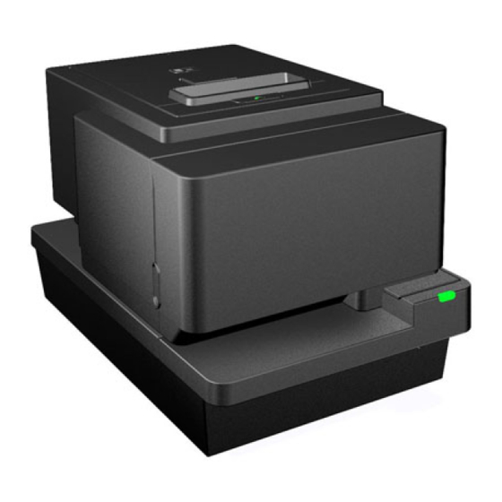
DIEBOLD NIXDORF P1300 Programming Manual (256 pages)
Hybrid Printer
Brand:
DIEBOLD NIXDORF
| Category:
Printer
| Size: 4 MB
Table of Contents
Table of Contents
2
General
12
Printer Basic Functions
12
Receipt
12
Slip
13
Internal Buffers
13
RAM (Total Size: IRAM 3MB, DRAM 16MB)
13
Flash Memory (Total Size: 8MB)
13
Summary of Option Interface
14
RS232C Interface
14
Emulation
15
Command Descriptions
26
Printer Function Command
26
Clear Printer
26
Perform Full Knife Cut
26
Perform Partial Knife Cut
26
Generate Tone
26
Initialize Printer
26
Select Sensors to Stop Printing
27
Enable or Disable Feed Button
27
Generate Pulse to Open Cash Drawer
27
Select Cut Mode and Cut Paper
27
Print Configuration Form
28
Receipt Shooting Flush
28
Play Melody
28
Switch the Printer into Sleep-Mode
29
Close Form
29
Open Form
29
Return Home
30
Set Slip Paper Eject Length
30
Select Receipt or Slip for Printing
30
Select Receipt or Slip for Setting Line Spacing
30
Set Slip Paper Waiting Time
31
Select Slip Station
31
Select Receipt Station
31
Release Paper
31
Vertical Positioning and Print Commands
32
Print and Feed Paper One Line
32
Print and Carriage Return
32
Feed N Print Lines
32
Feed N Dot Rows
32
Add N Extra Dot Rows
32
Print
33
Set Line Spacing to 1/6 Inch
33
Set Line Spacing
33
Print and Feed Paper
34
Print and Feed N Lines
34
Set Horizontal and Vertical Minimum Motion Units
34
Print and Reverse Feed Paper
34
Print and Reverse Feed N Lines
35
Reverse Feed N Lines
35
Reverse Feed N Dots
35
Print and Eject Slip
35
Set/Cancel Cut Sheet Reverse Eject (ESCPOS Emulation Only)
35
Set Print Position to the Beginning of Print Line (ESCPOS Emulation Only)
36
Horizontal Positioning Commands
36
Horizontal Tab
36
Set Column
37
Set Absolute Starting Position
37
Set Horizontal Tabs
37
Set Relative Print Position
37
Select Justification
38
Set Left Margin
38
Set Print Area Width
39
Print Characteristic Commands
40
Select Double-Wide Characters
40
Select Single-Wide Characters
40
Select 90 Degrees Counter-Clockwise Rotated Print
40
Select Pitch (Column Width)
40
Set Character Right-Side Spacing
40
Select Print Modes
41
Select or Cancel Font Smoothing
41
Select or Cancel User-Defined Character Set
41
Select or Cancel Underline Mode
44
Copy Character Set from ROM to RAM
44
Cancel User-Defined Characters
44
Select or Cancel Emphasized Mode
44
Select Double Strike
44
Select or Cancel Italic Print
45
Select International Character Set (DN Emulation)
45
Select International Character Set.(ESCPOS Emulation)
46
Select Character Code Table(ESCPOS Emulation)
47
Select or Cancel Unicode(UTF-16) Mode
48
Select or Cancel 90 Degrees Clockwise Rotated Print
48
Select Print Color
49
Select or Cancel Upside & down Printing Mode
49
Select Character Size
49
Select or Cancel White/Black Reverse Printing Mode
50
Selects Superscript or Subscript Modes
50
Select or Cancel Unidirectional Printing Mode
50
Select Character Font (ESCPOS Emulation Only)
51
Graphics Commands
52
Print Raster Graphics
52
Print Raster Color Graphics
52
Define Bitmap File as Logo
52
Select Bit Image Mode
53
Select Bit-Image Mode - Line Graphics
54
Turn On/Off TIFF Compression
55
Print Advanced Raster Graphics
55
Select Single Density Graphics
56
Select Double-Density Graphics
56
Print Raster Bit Image
56
Select the Current Logo
56
Define Bit Image as Logo
57
Print Current Logo
58
Print Logo
58
Define Logo in Flash Memory
59
Convert 6 Dots/MM Bitmap to 8 Dots/MM
59
Transmit Entire Capacity of User-Defined Logo in Flash Memory
59
Transmit Remaining Size for User-Defined Logo Area in Flash Memory
60
Transmit Remaining Size for User-Defined Logo Area in RAM
60
Transmit the Key Code for User-Defined Logo in Flash Memory
61
Delete All Logo in Flash Memory
61
Delete User-Defined Logo in Flash Memory
61
Define Logo in Flash Memory by the Key Code
62
Print User-Defined Logo in Flash Memory
64
Transmit the Key Code for User-Defined Logo in RAM
64
Delete All User-Defined Logo in RAM
65
Delete User-Defined Logo in RAM
66
Define Logo in RAM by the Key Code
66
Print User-Defined Logo in RAM
67
Enable Watermark Printing
67
Transmits Set Values for Watermark
69
Transmit Remaining Size for User-Defined Logo Area
69
Store the Graphics Data in the Print Buffer
70
Print the Graphics Data in the Print Buffer
70
Download Logo Image
71
Cancel Set Values for Top/Bottom Logo Printing
72
Transmits Set Values for Top/Bottom Logo Printing
72
Set Top Logo Printing
74
Set Bottom Logo Printing
74
Make Extended Settings for Top/Bottom Logo Printing
75
Enable/Disable Top/Bottom Logo Printing
75
Define Windows BMP Graphics Data in Flash Memory
76
Define Windows BMP Graphics Data in RAM
76
Reverse Color Text Mode
78
Monochrome Shade Mode
78
Color Shade Mode
79
Apply Shading to Logo
79
Merge Watermark Mode
80
Form and Merge Real-Time Surround Graphic
80
Save Graphics Buffer as Logo
81
Background Logo Print Mode
81
User Storage Status
81
Apply Margin Message Mode
82
Shade and Store Logo
83
Logo Print with Knife Cut
83
Set Interpretation of "Set Current Color" Command
83
Set Colorization
84
Set Attribute Mapping
86
Set Interpretation of "Set Current Color" Command
87
Status Commands
88
Transmit Peripheral Device Status
89
Transmit Printer Status
89
Transmit Printer ID
89
Transmit Printer ID, Remote Diagnostics Extension
92
Enable/Disable Automatic Status Back (ASB)
94
Initialize Maintenance Counter
96
Transmit Maintenance Counter
98
Transmit Status
100
Send Printer Firmware Version
101
Real Time Commands Disabled
101
Execute Impact Head Failure Detection
101
Execute Head Failure Detection
102
Get Detail of Head Failure Detection
102
Set Control Point
103
Real Time Commands
104
Real Time Status Transmission
104
Real Time Request to Printer
106
Enable/Disable Real-Time Command
107
Generate Pulse in Real-Time
108
Execute Power-Off Sequence
108
Control Buzzer (Internal Buzzer)
109
Select Peripheral Device
109
Clear Buffer(S)
109
Extended Real-Time Status Transmission
110
Real Time Printer Status Transmission
115
LED Control Request
115
Real-Time Printer Maintenance
116
Bar Code Commands
118
Select Printing Position of HRI Characters
118
Select Pitch for HRI Characters
118
Select Bar Code Height
118
Print Bar Code
118
Print Bar Code (ESCPOS Emulation)
118
Print Bar Code(2D Mode)
123
Print Gs1Databar (RSS), Data Length Specified
124
Pint Gs1Databar (RSS Barcode), Null Terminated
125
Set Gs1Databar (RSS) Parameters
125
Select Bar Code Width
125
PDF417: Set the Number of Columns in the Data Region
125
PDF417: Set the Number of Rows
126
PDF417: Set the Width of the Module
126
PDF417: Set the Row Height
127
PDF417: Set the Error Correction Level
127
PDF417: Select the Options
128
PDF417: Store the Data in the Symbol Storage Area
128
PDF417: Print the Symbol Data in the Symbol Storage Area
128
PDF417: Transmit the Size Information of the Symbol Data in the Symbol Storage Area
129
QR Code: Select the Model
129
QR Code: Set the Size of Module
129
QR Code: Select the Error Correction Level
130
QR Code: Select Encode Modes
130
QR Code: Store the Data in the Symbol Storage Area
131
QR Code: Print the Symbol Data in the Symbol Storage Area
131
QR Code: Transmit the Size Information of the Symbol Data in the Symbol Storage Area
131
2-Dimensional GS1 Databar: Set the Module Width
132
2-Dimensional GS1 Databar: Set the Maximum Width of GS1 Databar Expanded Stacked
132
2-Dimensional GS1 Databar: Store Data in the Symbol Storage Area
133
2-Dimensional GS1 Databar: Print Data in the Symbol Storage Area
133
Select PDF 417 Parameters
134
Datamatrix: Set the Symbol Type, Number of Columns, Number of Rows
136
Datamatrix: Set the Size of the Module
138
Datamatrix: Store the Data in the Symbol Storage Area
138
Datamatrix: Print the Symbol Data in the Symbol Storage Area
139
Datamatrix: Transmit the Size Information of the Symbol Data in the Symbol Storage Area
140
Page Mode Commands
141
Print and Return to Standard Mode
141
Select Standard Mode
142
Set Printing Area in Page Mode
143
Macro Commands
146
Start and Terminate Macro Definition
146
Execute Macro
146
User Data Storage Commands
147
Write User Defined Data
147
Read User Defined Data
147
Select Memory Type for User Defined Data
147
Flash Memory Allocation for User-Defined Storage Area
148
Erase User-Defined Storage Area in Flash Memory
148
Printer Setting Change
149
Read Printer Setting
155
LED Configuration
155
Read LED Configuration
156
Change into the User Setting Mode
156
End the User Setting Mode Session
157
Changes the Memory Switch
157
Transmits the Host the Value for the Memory Switch
159
Set the Customized Setting Values
159
Transmit the Customized Setting Values
165
Set the Configuration Item for the Serial Interface
167
Transmit the Configuration Item for the Serial Interface
168
Set Conditions for USB Communication
168
Transmit Conditions for USB Communication
168
Set Serial Number
170
Set Production Date
170
Set Paper Type
170
Text Strike-Through Mode
171
Download Paper Type Description
171
Return Paper Type Description
171
Set Temporary Max Target Speed
174
Enable/Disable Transmission of Paper Status (ESCPOS Emulation Only)
175
Select the Print Speed (ESCPOS Emulation Only)
175
Select Slip Lines Per Inch
177
Select Narrow Slip Configuration Option to Ignore N Leading Spaces
177
Select Narrow Slip 51 -Column Compressed Print Option
178
Select Delete Slip Trailing Spaces Option
178
Select (21 and 25-Line) Rotated Slip Print Options
178
Select Slip Stop Options
179
Enables or Disables the 1B 2110 Command
179
Enables or Disables the 1B 20 N Command
179
Enables or Disables the 1D 50 X y Command
179
Enables or Disables the 1D 4C N L N H and 1D 57 N L N H Commands
180
Enables or Disables the 1B 61 N Command
180
Asian Character Command
181
Select Print Modes for Asian Characters
181
Select Asian Character Mode
181
Turn Underline Mode ON/OFF in Asian Mode
181
Cancel Asian Character Mode
181
Define User-Defined Asian Characters
182
Select Asian Character Code System
183
Set Asian Character Spacing
183
Set Quadruple Mode ON/OFF in Asian Mode
183
Ipl(Initial Program Loader) Command
184
Switch to Flash Download Mode
184
Select Flash Memory Sector to Download
184
Get Firmware Sector CRC
184
Return IPL Firmware CRC
184
Erase All Flash Memory
185
Return Main Firmware CRC
185
Erase Selected Flash Sector
185
Download to Active Flash Sector
185
Reboot the Printer
185
Flash Download Commands in Main Firmware
186
Flash Firmware
186
Activate Firmware in the Alternative Area
186
Diagnostic Commands
188
Execute Test Print
188
Dot Check Pattern Test
188
Sensor Calibration
188
Retrieve Detail Log
190
Appendix 1 Character Sets
192
Character Code Table Page 0 (PC437 : Usa,Standard Europe)
192
Character Code Table Page 1 (PC850: Multilingual Latin I)
192
Character Code Table Page 2 (PC852: Latin II)
193
Character Code Table Page 3 (PC860: Portuguese)
193
Character Code Table Page 4 (PC863: Canadian French)
194
Character Code Table Page 5 (PC865: Nordic)
194
Character Code Table Page 6 (PC858: Multilingual I + Euro)
195
Character Code Table Page 7 (PC866: Russian)
195
Character Code Table Page 8 (WPC1252: Latin I)
196
Character Code Table Page 9 (PC862: Hebrew)
196
Character Code Table Page 10 (PC737: Greek)
197
Character Code Table Page 11 (PC874: Thai)
197
Character Code Table Page 12 (PC857: Turkish)
198
Character Code Table Page 13 (WPC1251: Cyrillic)
198
Character Code Table Page 14 (WPC1255: Hebrew)
199
Character Code Table Page 15 ((KZ_1048: Kazakh)
199
Character Code Table Page 16 (WPC1254: Turkish)
200
Character Code Table Page 17 (WPC1250: Central Europe)
200
Character Code Table Page 18 (WPC28591: Latin 1)
201
Character Code Table Page 19 (WPC28592: Latin 2)
201
Character Code Table Page 20 (WPC28599: Turkish)
202
Character Code Table Page 21 (WPC28605: Latin 9)
202
Character Code Table Page 22 (PC864: Arabic)
203
Character Code Table Page 23 (PC720: Arabic)
203
Character Code Table Page 24 (WPC1256: Arabic)
204
Character Code Table Page 25 (WPC28596: Arabic)
204
Character Code Table Page 26 (KATAKANA: Asia)
205
Character Code Table Page 27 (PC775: Baltic)
205
Character Code Table Page 28 (WPC1257: Baltic)
206
Character Code Table Page 29 (WPC28594: Baltic)
206
Character Code Table Page 30 (WPC1253: Greek)
207
Appendix 2 Printable Area
208
Appendix 3 Eco Function
209
General
209
Paper Reduction
209
Remove Upper Space
209
Remove Lower Space
210
Line Space Reduction
210
Line Feed Reduction
211
Barcode Height Reduction
211
Registered Logo Removal
212
Force Single High Font
212
Remove Lines Containing Only Spaces
212
Power Reduction
213
Bold Font Removal
213
Force Single Wide Font
213
No White/Black Reverse Printing
214
Stand-By Mode
214
Power off Mode
214
Speed Reduction
214
Density Reduction
214
Affected Commands
215
Appendix 4 Thai Font Support
216
Outline
216
Thai Character Configuration
216
Thai Character Data Procedure
217
The Notes for this Function
217
Appendix 5 Paper Low Detection
219
Appendix 6 Barcode Information
220
GS K Print Barcode
220
Diagnostics
232
10. Offline Diagnostic
232
Offline Printer Configuration
232
P1300 Diagnostic Functions
246
Selftest Printout
246
Sensor Test
246
Printer Errors
249
11. Error Detection
249
12. LED Indication
252
LED Pattern in Auto Mode
252
LED Pattern in User Mode
254
Advertisement
DIEBOLD NIXDORF P1300 User Manual (75 pages)
Hybrid Printer
Brand:
DIEBOLD NIXDORF
| Category:
Printer
| Size: 4 MB
Table of Contents
Table of Contents
2
Manufacturer's Declaration and Approval
4
Supplier's Declaration of Conformity
6
Safety Summary
7
Important Information to the User
10
Unpacking
12
Product Overview
13
Introduction
13
Features
13
Applicable Model
13
Accessories
14
Specifications
15
General
15
Internal Buffers
17
Thermal Head Basic Performance
17
Slip Printing
18
General
18
Impact Dot Matric Head Basic Performance
19
Main Card
19
Standard Interface Card
19
Option Interface Card
20
Reliability
20
Life
20
Environmental Usage Conditions
21
Options
22
Receipt Roll
23
Appearance
26
Front/Rear View
26
Receipt LED and Feed Button
27
Slip Table LED
28
Power Button
28
Connectors
29
Specification of Interface & Power Connector
30
Set up Procedure
34
Requirements for Operation
34
Setting up the Printer
36
Turning off the Printer
37
Installation Procedure
38
Connecting the Power Cord and Interface Cable
38
Connect to Power Adapter
39
Connect Via Standard USB Type-B Cable
40
Connect Via Option Card (RS232)
41
Connect Via Y-Cable
42
Connecting Via Cash Drawer
43
Choosing a Location
44
Loading the Receipt Roll
45
Diagnostics
48
Offline Diagnostic
48
Service Menu Structure - Main Menu
49
Main Menu / Diagnostic
50
Main Menu / Configuration / Hardware
51
Main Menu / Configuration / Software
52
Main Menu / Configuration / Print Options
53
Main Menu / Configuration / Configuration & Counters
53
Main Menu / Configuration / RS232
54
Main Menu / Configuration / Slip Options
55
General Maintenance
56
Cleaning the Covers
56
Cleaning the Thermal Print Head
57
Replacing Ribbon Cassette
58
Removing Ribbon Cassette
58
Installing Ribbon Cassette
59
Troubleshooting
61
Removing Jammed Paper
61
Resetting Cutter Failure or Jam
62
Slip Station Paper Jam Clearance
65
Common Problems & Solutions
66
Appendix
69
Printer will Feed 1-Inch Paper Length under below Scenario
69
LED Indication Table
69
Sensor Calibration Value
71
Printer Cable List for P1300
73
Advertisement
Related Products
DIEBOLD NIXDORF P1200
DIEBOLD NIXDORF P1.0-APL-AIO
DIEBOLD NIXDORF Categories
Touch terminals
Monitor
Cash Counter
Printer
Motherboard
More DIEBOLD NIXDORF Manuals
Login
Sign In
OR
Sign in with Facebook
Sign in with Google
Upload manual
Upload from disk
Upload from URL