Sign In
Upload
Manuals
Brands
delta-mobrey Manuals
Measuring Instruments
2468CC
delta-mobrey 2468CC Manuals
Manuals and User Guides for delta-mobrey 2468CC. We have
2
delta-mobrey 2468CC manuals available for free PDF download: Operating Manual
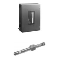
delta-mobrey 2468CC Operating Manual (166 pages)
Electronic Gauging System
Brand:
delta-mobrey
| Category:
Measuring Instruments
| Size: 2 MB
Table of Contents
Introduction to the Hydrastep 2468 Electronic Gauging System
13
Table of Contents
13
Figure 1.1 - Front Panel of the Hydrastep 2468 Gauging System, with Local Display
14
Figure 1.2 - Schematic of Resistance Measuring Cell and Electrodes
15
Water Level Measurement
15
Figure 1.3 - Typical Hydrastep 2468 System Installation
16
Hydrastep 2468 Electronic Gauging System
17
Input Boards
17
Display Boards
17
Output Boards
18
Option Details
18
System Options
18
System Faults (2468Cb or 2468Cd)
18
Remote Display Units
18
Hydrastep 2468 Upgrade Paths and Available Options
19
Table 1.1 - Upgrade Paths and Available Options
19
2468Ca & 2468Cc Single Power Supply Version
21
Electrode Cabling System
23
Electronic Enclosure
23
Introduction
23
Analogue Output Drive Capability
25
Input Board (Pcb 24680501 and Pcb 24680516)
25
Remote Display Drive Capability
25
Display Board (Pcb 24680515)
26
Link LK1
26
Links LK2, LK3, LK4 and LK5
26
Pcb Interconnections
26
Installation
27
Mechanical Installation
27
Electrical Installation
29
Electrode Connections
29
Connecting Cables to Water Column Electrodes
30
Connecting the Electrode Cable Assemblies to 2468 Enclosure
30
Hydrastep Power Supply Cable
31
Analogue Output Connection
33
Opto-Isolated Fault Output Connection
34
Analogue Output Configuration
35
Input Board (Pcb 24680501 or 24680516)
35
System Configuration
35
Electrode Error Configuration
36
Pulsed Output Setting
36
Configuring the Unit to Detect Electrode Error
37
Configuring the 'Number of Electrodes' Switch
38
Display Board 24680515
38
Link LK1 Setting
38
2.5.2.4 'Compatibility' Setting
40
Switching Threshold' Setting
40
Fault Analysis & Corrective Action
41
Component Replacement
43
Removing the Input Board (24680501 or 24680516)
43
Parts List - Hydrastep 2468 Ca & CC Versions
44
Refitting the Display Board
44
Refitting the Input Board
44
Removing the Display Board 24680515
44
Specification
45
- Relay Output Board Option
55
2.1 Storage & Pre-Installation Inspection
57
3A.1 General Description
57
3A.2 Installation
57
3A.2.1.1 Storage Area
57
3A.2.1.2 Pre-Installation Inspection
57
2.2 Mechanical Installation
58
3A.2.2.1 Fitting the Nylon Spacers to the Relay Output Board
58
3A.2.2.2 Mounting the Relay Output Board on to the Input Board
58
2.3 Electrical Installation
59
3A.2.3.1 PCB Interconnections
59
3A.2.3.2 Relay Output Connections
59
3A.3 Relay Board Configuration
60
3.1 Relay Output Board
61
3A.3.1.1 Configuring the Relay Output Board
61
3A.3.1.3 Relay Energisation ('In Steam' or 'In Water') - SW5
62
3A.3.1.4 Electrode/Alarm Operation (RL1 Function Only) - SW6
62
3A.3.1.5 System Fault Output
62
3.2 Alarm and Tripping Facilities
63
3A.3.2.1 Philosophy
63
3A.3.2.2 Relay Interconnections for Alarm/Tripping Systems
63
3A.3.2.3 'One out of Two' Relay Alarm System
64
3A.3.2.4 'Two out of Two' Relay Alarm System
65
3A.4 Component Replacement
66
4.2 Parts List - Relay Output Board 24680504
66
Replacement of Nylon Spacers
66
3A.5 Specification
67
Delay Relay Output Board Option
69
2.1 Storage & Pre-Installation Inspection
71
3B.1 General Description
71
3B.2 Installation
71
3B.2.1.1 Storage Area
71
3B.2.1.2 Pre-Installation Inspection
71
2.2 Mechanical Installation
72
3B.2.2.1 Fitting the Nylon Spacers to the Delay Relay Output Board
72
3B.2.2.2 Mounting the Delay Relay Output Board on to the Input Board
72
2.3 Electrical Installation
73
3B.2.3.1 PCB Interconnections
73
3B.2.3.2 Relay Output Connections
73
3B.3 Delay Relay Board Configuration
74
3.1 Delay Relay Output Board
75
3B.3.1.1 Configuring the Delay Relay Output Board
75
3B.3.1.2 Electrode/Relay Selection (Relays RL1, RL2, RL3 & RL4) - SW1 to SW4
75
3B.3.1.3 Relay Energisation ('In Steam' or 'In Water') - SW5
76
3B.3.1.4 Electrode/Alarm Operation (RL1 Function Only) - SW6
76
3B.3.1.5 System Fault Output
76
3B.3.1.6 Delay Circuit Configuration
77
3B.3.1.7 Configuring the Delay Circuit Split Pads
78
3.2 Alarm and Tripping Facilities
79
3B.3.2.1 Philosophy
79
3B.3.2.2 Relay Interconnections for Alarm/Tripping Systems
79
3B.3.2.3 'One out of Two' Relay Alarm System
80
3B.3.2.4 'Two out of Two' Relay Alarm System
81
3B.4 Component Replacement
82
4.1 Replacement of Nylon Spacers
82
4.2 Parts List - Delay Relay Output Board 24680509
82
Opto-Isolated Output Board Option
85
2.1 Storage & Pre-Installation Inspection
87
3C.1 General Description
87
3C.2 Installation
87
3C.2.1.1 Storage Area
87
3C.2.1.2 Pre-Installation Inspection
87
2.2 Mechanical Installation
88
3C.2.2.1 Fitting Nylon Spacers to the Opto-Isolated Output Board
88
2.3 Electrical Installation
89
3C.2.3.1 PCB Interconnections
89
3C.2.3.2 Opto-Isolated Output Connections
89
3C.3 Opto-Isolated Output Board Configuration
90
3.1 Configuring the Opto-Isolated Output Board
91
3C.3.1.1 Electrode/Opto-Output Selection (Opto-1, Opto-2, Opto-3 & Opto-4 Outputs) - SW1 to SW4
91
3C.3.1.2 Electrode/Alarm Operation (Output 1 Function Only) - SW6
92
Sw5
92
3C.3.1.4 System Fault Output
93
3.2 Alarm and Tripping Facilities
94
3C.3.2.1 Philosophy
94
3C.3.2.2 Opto-Output Interconnections for Alarm/Tripping Systems
94
3C.3.2.3 'One out of Two' Opto-Output Alarm System
95
3C.3.2.4 'Two out of Two' Opto-Output Alarm System
96
3C.4 Component Replacement
97
4.1 Replacement of Nylon Spacers
97
4.2 Parts List - Opto-Isolated Output Board 24680505
97
3C.5 Specification
98
Remote Display Options 24683B, C, & D
99
Remote Display Options
101
Configuration
102
Reconfiguring the 24683B and 24683C Remote Display
102
Reconfiguring the 24683D Remote Display
103
Installing the 24683B and 24683C Panel Mounted Units
104
Installing the 24683D Wall Mounted Unit
104
Mechanical Installation
104
Electrical Installation
105
Star and Daisy Chain Connections
106
Example of a 'Star Connected' System
107
Example of a `Daisy Chain' System
108
Connecting Cables to the Remote Display
109
Connecting the Display Cables to Hydrastep 2468
110
Fault Analysis and Corrective Action
111
System Operation
111
Component Replacement
114
Specification
115
Installation Procedures
133
Ambient Conditions
135
Handling Precautions
135
Inspection
135
Installation of Water Column
135
Physical Protection
135
Scope of Procedures
135
Storage
135
Inspection of Mechanical Installation Work
138
Fault Repair and Commissioning
141
Background
143
Safety Precautions
143
3.1.3.1 Low Pressure Electrodes
144
Electrode and Electrode Seal Leaks
144
Water Column Isolation
144
3.1.3.2 High Pressure Electrodes
145
3.1.3.3 Tightening Procedure for High Pressure Electrode Installation
145
And Gaskets
145
Procedure for Changing the Low Pressure Electrodes
145
Procedure for Changing High Pressure Electrodes
146
Vent and Drain Valve Repairs
146
Water Column Commissioning or Recommissioning
146
Water Column or Pipework Blockage
147
Water Column Transient Response
147
Unit Description
149
Low Pressure Electrodes
151
High Pressure Electrodes
152
Water Column (L.p.)
153
Water Column (H.p.)
154
Water Column (H
155
Advertisement
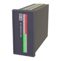
delta-mobrey 2468CC Operating Manual (110 pages)
Electronic Gauging System
Brand:
delta-mobrey
| Category:
Measuring Instruments
| Size: 5 MB
Table of Contents
Table of Contents
7
Chapter 1 - Introduction
11
Hydrastep 2468 Steam and Water Gauging System
11
How It Works
12
Electronics in the Controller Unit
15
Input Board
15
Display Board
16
Output Boards (Optional)
16
Chapter 2 - Mechanical Installation
19
Water Column and Electrodes Installation
19
Controller Unit Installation
19
Remote Display Unit Installation
20
Chapter 3 - Electrical Installation
21
Input Board
21
Power Supply Options on the Input Board
21
Power Cables and Connections for the Input Board (Ac Mains Version)
23
Power Cables and Connections for the Input Board (DC Supply Version)
24
Electrode Cables and Connections on the Input Board
25
Input Board: Analogue Output (Optional)
30
Electrode Error Configuration (Standard) on the Input Board
32
Display Board
35
Configuration Options for the Display Board
35
Compatibility Setting for New and Legacy Input Boards
37
Remote Display Unit Connections
37
Opto-Isolated Fault Output Connection (Optional)
37
Output Option Boards
39
Installing a New Output Board
41
Configuration Options on an Output Board
42
Connections to an Output Board
46
Chapter 4 - Starting-Up the First Time
49
Hydrastep Start-Up
49
Chapter 5 - Troubleshooting
51
Quick Troubleshooting Chart
51
Troubleshooting the Controller Unit
52
Fault Analysis and Corrective Actions
52
Replacing Input and Display Boards
55
Fitting or Replacing an Optional Output Board
56
Troubleshooting the Remote Displays
58
Fault Analysis and Corrective Actions
58
Troubleshooting the Water Columns
62
Background
62
Safety Precautions
62
Water Column Isolation
63
Electrode and Electrode Seal Leaks
63
Changing the Low-Pressure Electrodes and Gaskets
65
Changing the High-Pressure Electrodes and Gaskets
66
Water Column Commissioning or Recommissioning
66
Venting and Draining for Valve Repairs
67
Water Column Transient Response
67
Clearing Water Column and Pipework Blockages
68
Water Column Life
68
A.1 Controller Unit and Electrodes
69
Appendix B - Specifications
75
Hydrastep Controller Unit Specifications
75
Core Specifications for the Controller Unit
75
Specifications for the Optional Relay Output Board
76
Specifications for the Optional Delay-Relay Output Board
76
Remote Display Unit Specifications
77
Cabling Specifications for the Remote Display Units
77
Electrodes and Water Columns Specifications
78
Core Specifications for the Electrodes
78
Core Specifications for the Water Columns
79
Appendix C - Parts Lists
81
Hydrastep Controller Unit Parts
81
Core Parts for the Controller Unit
81
Relay Output Option Board (PCB 24680504
81
Delay Relay Output Option Board (PCB 24680509
81
Accessories
82
Water Column and Electrode Accessories
82
Appendix D - Remote Display Units
83
Remote Display Options
83
Reconfiguring the 24683Bb and 24683C Displays
85
Reconfiguring the 24683D Display
86
Installing the 24683Bb and 24683C Units in a Panel
87
Installing the 24683D Wall Mounted Unit
87
Electrical Connections
89
One Remote Display Unit Powered by the Controller Unit
89
Other Remote Display Units Powered by Local Supplies
90
Loop Resistance
92
Connecting Cables to the Remote Display
92
Connecting the Display Cables to the Controller Unit
92
System Operation
93
Appendix E - Hydrastep Water Columns and Electrodes
95
Water Columns
95
Low-Pressure Water Columns
95
High-Pressure Water Columns
95
Supercritical High-Pressure Water Column
96
Electrodes
99
Low-Pressure Electrodes
99
High-Pressure Electrodes
100
Installation Procedures
101
Scope of Procedures
101
Storage
101
Installation of the Water Column
102
Inspection of Mechanical Installation Work
104
Appendix F -- CSA Certification Drawings
107
Csa Control Drawings
107
Advertisement
Related Products
delta-mobrey 2468CA
delta-mobrey Hydrastep 2468 Series
delta-mobrey Mobrey 402SD
delta-mobrey Mobrey 433SD
delta-mobrey Mobrey 442SD
delta-mobrey Mobrey MCU200 Series
delta-mobrey Mobrey MCU201
delta-mobrey Mobrey MCU203
delta-mobrey Categories
Switch
Transmitter
Measuring Instruments
Monitor
Control Unit
More delta-mobrey Manuals
Login
Sign In
OR
Sign in with Facebook
Sign in with Google
Upload manual
Upload from disk
Upload from URL