
Related Manuals for delta-mobrey Hydrastep 2468 Series


Summary of Contents for delta-mobrey Hydrastep 2468 Series
- Page 1 Operating Manual 24685033, Rev. AE Hydrastep 2468 June 2011 Hydrastep 2468CA and 2468CC lectronic Gauging System (Single Power Supply Version) www.delta-mobrey.com...
- Page 4 About this manual This manual describes the Hydrastep 2468CA and 2468CC Electronic Gauging Systems along with the recommended options. Except where stated otherwise, the information contained in this manual can be assumed to apply to either system. This manual is divided into three parts; the first covers the electrical/electronic system; the second describes the pressure parts;...
- Page 5 SYMBOLS USED IN THIS MANUAL AND ON THE UNIT Symbol Meaning Direct Current Alternating Current Earth (ground) terminal Protective conductor terminal Caution (refer to accompanying documents)
- Page 7 Part 1 Hydrastep 2468CA & 2468CC Electronic Gauging System Pt.1 24685033...
- Page 8 Pt.1 24685033...
- Page 9 DANGEROUS VOLTAGES ARE PRESENT IN THIS EQUIPMENT. ANY WARNING NOTICES PROCEDURES CONTAINED THIS MANUAL OR ON THE EQUIPMENT SHOULD BE STRICTLY OBSERVED TO MAINTAIN SAFETY. THE USE OF THIS EQUIPMENT IN A MANNER NOT SPECIFIED IN THIS MANUAL MAY IMPAIR PROTECTION PROVIDED THIS...
- Page 10 Pt.1 24685033...
- Page 11 Part 1 Contents Chapter 1 Introduction to the Hydrastep 2468 Electronic Gauging System Chapter 2 2468CA & 2468CC Single Power Supply Version Chapter 3a 2468 - Relay Output Board Option Chapter 3b Delay Relay Output Board Option Chapter 3c 2468 Opto-isolated Output Board Option Chapter 4 Remote Display Options 24683B C &...
- Page 12 Pt.1 24685033...
-
Page 13: Table Of Contents
Hydrastep 2468CA and 2468CC Manual Introduction to the Hydrastep 2468 Electronic Gauging System Introduction to the Hydrastep 2468 Electronic Gauging System Contents Page No. WATER LEVEL MEASUREMENT ............3 HYDRASTEP 2468 ELECTRONIC GAUGING SYSTEM ....... 5 1.2.1 INPUT BOARDS .................. 5 1.2.2 DISPLAY BOARDS ................ -
Page 14: Figure 1.1 - Front Panel Of The Hydrastep 2468 Gauging System, With Local Display
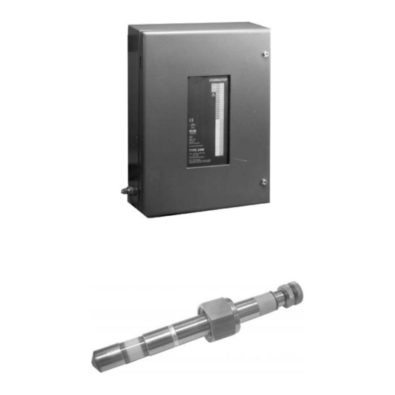
Introduction to the Hydrastep 2468 Electronic Gauging System Hydrastep 2468CA and 2468CC Manual 0040 Figure 1.1 - Front panel of the Hydrastep 2468 gauging system 24685033... -
Page 15: Water Level Measurement
Hydrastep 2468CA and 2468CC Manual Introduction to the Hydrastep 2468 Electronic Gauging System WATER LEVEL MEASUREMENT The Hydrastep 2468 Electronic Gauging System is designed as an electronic alternative to water level gauges on boilers, giving a more reliable and safer water level indication than conventional visual gauges. -
Page 16: Figure 1.3 - Typical Hydrastep 2468 System Installation
Introduction to the Hydrastep 2468 Electronic Gauging System Hydrastep 2468CA and 2468CC Manual Figure 1.3 - Typical Hydrastep 2468 System Installation 24685033... -
Page 17: Hydrastep 2468 Electronic Gauging System
Hydrastep 2468CA and 2468CC Manual Introduction to the Hydrastep 2468 Electronic Gauging System HYDRASTEP 2468 ELECTRONIC GAUGING SYSTEM The Hydrastep 2468 is a sophisticated and flexible electronic gauging system. It is supplied in two main versions: A Single Power Supply System with Local Level Display ... -
Page 18: System Faults (2468Cb Or 2468Cd)
Introduction to the Hydrastep 2468 Electronic Gauging System Hydrastep 2468CA and 2468CC Manual 1.2.3 SYSTEM FAULTS (2468CA OR 2468CC) System fault indication, a yellow LED and an opto-isolated output, is provided for a ‘water above steam’ condition, an electrode fault or wiring failure and the detection of an internal fault. -
Page 19: Hydrastep 2468 Upgrade Paths And Available Options
Hydrastep 2468CA and 2468CC Manual Introduction to the Hydrastep 2468 Electronic Gauging System HYDRASTEP 2468 UPGRADE PATHS AND AVAILABLE OPTIONS Table 1.1 describes the available versions of the Hydrastep 2468 Electronic Gauging System and their possible options. Available Options Existing System Comments Description Part No. - Page 20 Introduction to the Hydrastep 2468 Electronic Gauging System Hydrastep 2468CA and 2468CC Manual 24685033...
- Page 21 Hydrastep 2468CA and 2468CC Electronic Gauging Systems 2468CA & 2468CC Single Power Supply Version 2468CA & 2468CC Single Power Supply Version Contents Page No. INTRODUCTION ..................2-3 ELECTRODE CABLING SYSTEM ............2-3 ELECTRONIC ENCLOSURE ..............2-3 2.3.1 INPUT BOARD (PCB 24680501 AND PCB 24680516) ......2-5 2.3.1.1 Analogue Output Drive Capability ...........
- Page 22 2468CA & 2468CC Single Power Supply Version Hydrastep 2468CA and 2468CC Electronic Gauging Systems 2.5.2 DISPLAY BOARD 24680515 ............... 2-18 2.5.2.1 Link LK1 Setting ..............2-18 2.5.2.2 Configuring the ‘Number of Electrodes’ Switch ....2-18 2.5.2.3 ‘Switching Threshold’ Setting ..........2-20 2.5.2.4 ‘Compatibility’...
-
Page 23: Introduction
Hydrastep 2468CA and 2468CC Electronic Gauging Systems 2468CA & 2468CC Single Power Supply Version INTRODUCTION This chapter introduces the single power supply version of the Hydrastep 2468 Electronic Gauging System, its mechanical installation, system configuration, simple fault analysis/corrective action capability and its specification. ELECTRODE CABLING SYSTEM This system can have 8, 10, 12, 14, 16 electrodes and uses 18-core electrode cables. - Page 24 2468CA & 2468CC Single Power Supply Version Hydrastep 2468CA and 2468CC Electronic Gauging Systems Figure 2.1 - Outline drawing showing PCB layout and interconnections 24685033...
-
Page 25: Input Board (Pcb 24680501 And Pcb 24680516)
Hydrastep 2468CA and 2468CC Electronic Gauging Systems 2468CA & 2468CC Single Power Supply Version 2.3.1 INPUT BOARD (PCB 24680501 AND PCB 24680516) The input board processes the electrode inputs to provide water level data for display purposes and a current output representing the water level. Fault detection is also carried out where the condition of the electrode inputs are examined and a FAULT is indicated when: 1. -
Page 26: Display Board (Pcb 24680515)
2468CA & 2468CC Single Power Supply Version Hydrastep 2468CA and 2468CC Electronic Gauging Systems 2.3.3 DISPLAY BOARD (PCB 24680515) The display board receives its power supplies and electrode data from the input board. This data is decoded and used to illuminate the required LEDs mounted on the display board. The data is also converted to serial format for transmission to remote display units. -
Page 27: Installation
Hydrastep 2468CA and 2468CC Electronic Gauging Systems 2468CA & 2468CC Single Power Supply Version INSTALLATION This section deals with the mechanical installation of the electronic enclosure and the electrical connections required for the basic system. Any installation dealing with the options available for use on this version of the system are covered in Chapters 3 and 4. - Page 28 2468CA & 2468CC Single Power Supply Version Hydrastep 2468CA and 2468CC Electronic Gauging Systems Figure 2.2 - Installation diagram for the Hydrastep 2468 electronic gauging system unit 24685033...
-
Page 29: Electrical Installation
Hydrastep 2468CA and 2468CC Electronic Gauging Systems 2468CA & 2468CC Single Power Supply Version 2.4.2 ELECTRICAL INSTALLATION This section deals with the interconnection between the electrodes and the electronic enclosure, the connection of the ac mains power supply to the electronic enclosure and the analogue output connections from the electronic enclosure. -
Page 30: Connecting Cables To Water Column Electrodes
2468CA & 2468CC Single Power Supply Version Hydrastep 2468CA and 2468CC Electronic Gauging Systems 2.4.2.2 Connecting Cables to Water Column Electrodes (16 Electrode System – See page 2.WD.7 in the Wiring Drawings Section) The following assumes that the electrodes have been fitted to the water column. 1. -
Page 31: Hydrastep Power Supply Cable
Hydrastep 2468CA and 2468CC Electronic Gauging Systems 2468CA & 2468CC Single Power Supply Version 2.4.2.4 Hydrastep Power Supply Cable WARNING Mains voltages are present in this instrument when power is connected. De-energise before opening front cover. AC Powered Units (input board 24680501) The Hydrastep 2468C must be installed with a fuse or circuit breaker with a maximum rating of 5A mounted as close as practicable, in an easily reached location. - Page 32 2468CA & 2468CC Single Power Supply Version Hydrastep 2468CA and 2468CC Electronic Gauging Systems V oltage S election P lug V oltage S election P lug (S et to 240V ) (S et to 110V ) F u se F use T R A N S F O R M E R T R A N S FO R M E R (A) 24 0 V...
-
Page 33: Analogue Output Connection
Hydrastep 2468CA and 2468CC Electronic Gauging Systems 2468CA & 2468CC Single Power Supply Version 2.4.2.5 Analogue Output Connection WARNING Mains voltages are present in this instrument when power is connected. De-energise before opening front cover. Plug PL1 on each input board is used for the analogue output. A 2-core screened cable is required and is connected into a 2-way socket such that: ... -
Page 34: Opto-Isolated Fault Output Connection
2468CA & 2468CC Single Power Supply Version Hydrastep 2468CA and 2468CC Electronic Gauging Systems 2.4.2.6 Opto-Isolated Fault Output Connection WARNING Mains voltages are present in this instrument when power is connected. De-energise before opening front cover. Plug PL4 is used for the FAULT output. A 2-core screened cable, capable of taking 1A and 30V is required and is connected into its 2-way terminal block such that: Note: No fault present = Short circuit, <... -
Page 35: System Configuration
Hydrastep 2468CA and 2468CC Electronic Gauging Systems 2468CA & 2468CC Single Power Supply Version This concludes the electrical installation requirements for the basic instrument configuration. Connections within the enclosure for the options available will be covered in the Installation sections of the appropriate Chapter 3a (Relay Outputs), 3b (Relay with time delay Outputs), 3c (Opto-isolated Outputs) or Chapter 4 (Remote Display). -
Page 36: Pulsed Output Setting
2468CA & 2468CC Single Power Supply Version Hydrastep 2468CA and 2468CC Electronic Gauging Systems 2.5.1.2 Pulsed Output Setting As configured at the factory, the analogue output pulses if a fault condition occurs. 1. To disable this feature the split pad SP10 must be broken by cutting the track that passes between the pads. -
Page 37: Configuring The Unit To Detect Electrode Error
Hydrastep 2468CA and 2468CC Electronic Gauging Systems 2468CA & 2468CC Single Power Supply Version 2.5.1.4 Configuring the Unit to Detect Electrode Error WARNING Mains voltages are present in this instrument when power is connected. De-energise before opening front cover. 1. Disconnect the power supply. Gain access to the input PCB by opening the cover and removing the option board. -
Page 38: Display Board 24680515
2468CA & 2468CC Single Power Supply Version Hydrastep 2468CA and 2468CC Electronic Gauging Systems 2.5.2 DISPLAY BOARD 24680515 Switch SW1 on the Display Board must be set in accordance with the number of electrodes whose state is to be displayed. As shown in Table 2.2, the various switch settings allow you to specify the number of electrodes as: 8, 10, 12, 14 or 16. - Page 39 Hydrastep 2468CA and 2468CC Electronic Gauging Systems 2468CA & 2468CC Single Power Supply Version Note: Links LK1, LK2 and LK4 must be fitted. Links LK3 and LK5 must NOT be fitted. An invalid switch setting causes the main pattern column LEDs to display a chequered Figure 2.4- Location of display board links LK1 to LK5 &...
-
Page 40: Switching Threshold' Setting
2468CA & 2468CC Single Power Supply Version Hydrastep 2468CA and 2468CC Electronic Gauging Systems 2.5.2.3 ‘Switching Threshold’ Setting WARNING Mains voltages are present in this instrument when power is connected. De-energise before opening front cover. 1. Disconnect the power supply. Gain access to PCB 24680515 by opening the cover. 2. -
Page 41: Fault Analysis & Corrective Action
Hydrastep 2468CA and 2468CC Electronic Gauging Systems 2468CA & 2468CC Single Power Supply Version FAULT ANALYSIS & CORRECTIVE ACTION Faults in the system will generally be indicated by the YELLOW LEDs on the front panel and by the fault output on the display board. The main faults that are catered for are: ... - Page 42 2468CA & 2468CC Single Power Supply Version Hydrastep 2468CA and 2468CC Electronic Gauging Systems Indication Fault(s) Analysis and Corrective Action Top and bottom Incorrect wiring, 2. With the conductors touching each other, the level halves of Fault broken connection display should show electrode as being in steam. LED illuminated or damaged cable The above procedure checks the electrode wiring.
-
Page 43: Component Replacement
Hydrastep 2468CA and 2468CC Electronic Gauging Systems 2468CA & 2468CC Single Power Supply Version Indication Fault(s) Analysis and Corrective Action Chequered Wrong setting of Refer to Section 2.3 of this chapter and ensure that the pattern on RED Number of switch is set correctly. -
Page 44: Refitting The Input Board
2468CA & 2468CC Single Power Supply Version Hydrastep 2468CA and 2468CC Electronic Gauging Systems 2.6.1.2 Refitting the Input Board To refit the input board, carry out the removal procedure in the reverse order. 2.6.1.3 Removing the Display Board 24680515 The display board is attached to pillars mounted on the rear of the front panel by five securing nuts and washers. -
Page 45: Specification
Hydrastep 2468CA and 2468CC Electronic Gauging Systems 2468CA & 2468CC Single Power Supply Version SPECIFICATION Enclosure: 425mm x 325mm x 163mm (16.7in x 12.8in x 6.4in) Brushed stainless steel Wall-mounting lP65 / NEMA 4X Gland plate - stainless steel 250mm x 120mm (9.8in x 4.7in) Weight of unit: 12kg (26.4lb) - Page 46 2468CA & 2468CC Single Power Supply Version Hydrastep 2468CA and 2468CC Electronic Gauging Systems 2-26 24685033...
- Page 47 Hydrastep 2468CA and 2468CC Electronic Gauging Systems Wiring Diagrams for Single Power Supply Version Hydrastep 2468CA & 2468CC (Single Power Supply Version) Electrode Cable Wiring Diagrams Contents Page No. Figure 2.WD.1 - Electrode cable connections to 8 port column ..........3 Figure 2.WD.2 - Electrode cable connections to 10 port column ..........
- Page 48 Wiring Diagrams for Single Power Supply Version Hydrastep 2468CA and 2468CC Electronic Gauging Systems 2-WD. 24685033...
- Page 49 Hydrastep 2468CA and 2468CC Electronic Gauging Systems Wiring Diagrams for Single Power Supply Version Figure 2.WD.1 - Electrode cable connections to 8 port column 2-WD.3 24685033...
- Page 50 Wiring Diagrams for Single Power Supply Version Hydrastep 2468CA and 2468CC Electronic Gauging Systems Figure 2.WD.2 - Electrode cable connections to 10 port column 2-WD. 24685033...
- Page 51 Hydrastep 2468CA and 2468CC Electronic Gauging Systems Wiring Diagrams for Single Power Supply Version Figure 2.WD.3 - Electrode cable connections to 12 port column 2-WD.5 24685033...
- Page 52 Wiring Diagrams for Single Power Supply Version Hydrastep 2468CA and 2468CC Electronic Gauging Systems Figure 2.WD.4 - Electrode cable connections to 14 port column 2-WD. 24685033...
- Page 53 Hydrastep 2468CA and 2468CC Electronic Gauging Systems Wiring Diagrams for Single Power Supply Version Figure 2.WD.5 - Electrode cable connections to 16 port column 2-WD.7 24685033...
- Page 54 Wiring Diagrams for Single Power Supply Version Hydrastep 2468CA and 2468CC Electronic Gauging Systems 2-WD. 24685033...
- Page 55 Hydrastep 2468CA and 2468CC Electronic Gauging Systems 2468 - Relay Output Board Option 2468 - Relay Output Board Option Contents Page No. 3A.1 GENERAL DESCRIPTION ..................3 3A.2 INSTALLATION ......................3 3A.2.1 STORAGE & PRE-INSTALLATION INSPECTION ........3 3a.2.1.1 Storage Area ................3 3a.2.1.2 Pre-Installation Inspection ............
- Page 56 2468 - Relay Output Board Option Hydrastep 2468CA and 2468CC Electronic Gauging Systems Illustrations Figure 3a.1 - View of relay output board showing switch positions and output pin details ..6 Tables Table 3a.1 - Electrode selections for relays RL1 to RL4 ............. 3a-7 3a-2 24685033...
-
Page 57: 3A.1 General Description
Hydrastep 2468CA and 2468CC Electronic Gauging Systems Relay Output Board Option 3A.1 GENERAL DESCRIPTION The Relay Output Board (PCB 24680504) has four relays and is mounted on top of the input board using 3 nylon spacers. Electrical connection between the two boards is via plug and socket (SK1 on the input board and PL1 on the relay output board). -
Page 58: 2.2 Mechanical Installation
2468 - Relay Output Board Option Hydrastep 2468CA and 2468CC Electronic Gauging Systems 3A.2.2 MECHANICAL INSTALLATION The output board is mounted directly on top of the input board. The input board is supplied with three nylon spacers fitted. The output board is then aligned on its Berg socket/plug interconnection (PL1/SK1) and input board-mounted spacers and pressed home on to the spacers. -
Page 59: 2.3 Electrical Installation
Hydrastep 2468CA and 2468CC Electronic Gauging Systems Relay Output Board Option 3A.2.3 ELECTRICAL INSTALLATION This sub-section deals with the output of the states of the four relays. Two 8-way sockets are provided with each output board through which the relay outputs are delivered to their external destinations. -
Page 60: 3A.3 Relay Board Configuration
2468 - Relay Output Board Option Hydrastep 2468CA and 2468CC Electronic Gauging Systems 3A.3 RELAY BOARD CONFIGURATION The 24680504 Relay Output Board has three configuration switches: SW6: Selects Electrode or Alarm state for RL1. SW1 - SW4: Selects individual electrode for relays RL1 to RL4. ... -
Page 61: 3.1 Relay Output Board
Hydrastep 2468CA and 2468CC Electronic Gauging Systems Relay Output Board Option 3A.3.1 RELAY OUTPUT BOARD 3a.3.1.1 Configuring the Relay Output Board WARNING Mains voltages are present in this instrument when power is connected. De-energise before opening front cover. 1. Isolate the 2468 electronics enclosure from its power supplies. 2. -
Page 62: 3A.3.1.3 Relay Energisation ('In Steam' Or 'In Water') - Sw5
2468 - Relay Output Board Option Hydrastep 2468CA and 2468CC Electronic Gauging Systems 3a.3.1.3 Relay Energisation (‘In Steam’ or ‘In Water’) - SW5 This is a four-channel switch, one channel allocated per relay. The switch selects whether the relay is energised when the selected electrode is in water or is in steam. This switch is highlighted in Figure 3a.1 to provide additional information on channel identity and the switch ‘electrode state’. -
Page 63: 3.2 Alarm And Tripping Facilities
Hydrastep 2468CA and 2468CC Electronic Gauging Systems Relay Output Board Option 3A.3.2 ALARM AND TRIPPING FACILITIES The relay boards provide high and low water level alarm and trip facilities for the 2468 Hydrastep system. Four to eight relays can be made available for each input board fitted. 3a.3.2.1 Philosophy A requirement in regulations concerning steam-raising plant is the provision of an automatic low water level shutdown or trip device. -
Page 64: 3A.3.2.3 'One Out Of Two' Relay Alarm System
2468 - Relay Output Board Option Hydrastep 2468CA and 2468CC Electronic Gauging Systems 3a.3.2.3 ‘One out of Two’ Relay Alarm System Either of the relays involved can cause an alarm when their assigned electrode registers an alarm condition. The alarm condition is selected by switch SW5 to provide relay energisation in water EW or energisation in steam ES. -
Page 65: 3A.3.2.4 'Two Out Of Two' Relay Alarm System
Hydrastep 2468CA and 2468CC Electronic Gauging Systems Relay Output Board Option 3a.3.2.4 ‘Two out of Two’ Relay Alarm System This system requires both relays to operate to cause an alarm when their assigned electrodes register an alarm condition. Case 2a - Relays normally energised, de-energise both to trip (Relays shown in de-energised state) PL 2 PL 2... -
Page 66: 3A.4 Component Replacement
2468 - Relay Output Board Option Hydrastep 2468CA and 2468CC Electronic Gauging Systems 3A.4 COMPONENT REPLACEMENT The relay board contains no replaceable circuit components, failure of the board requires replacement of the entire board. The only component that can be replaced is the nylon spacer. 3A.4.1 REPLACEMENT OF NYLON SPACERS The replacement of nylon spacers fitted to the output board requires access to the non-... -
Page 67: 3A.5 Specification
Hydrastep 2468CA and 2468CC Electronic Gauging Systems Relay Output Board Option 3A.5 SPECIFICATION Outputs: 4 x Alarm/Trip Relays Relay Contact Rating: Maximum voltage: 250V 125V Maximum current: Maximum switching power: 1500VA 240W ( 30V) ( 60V) ( 125V) Type nA safety 100mA at 30Vdc Maximum initial contact resistance: 30m... - Page 68 2468 - Relay Output Board Option Hydrastep 2468CA and 2468CC Electronic Gauging Systems 3a-14 24685033...
- Page 69 Hydrastep 2468CA and 2468CC Electronic Gauging Systems Delay Relay Output Board Option Delay Relay Output Board Option Contents Page No. 3B.1 GENERAL DESCRIPTION 3B.2 INSTALLATION 3B.2.1 STORAGE & PRE-INSTALLATION INSPECTION ........3 3b.2.1.1 Storage Area ................3 3b.2.1.2 Pre-Installation Inspection ............3 3B.2.2 MECHANICAL INSTALLATION ..............
- Page 70 Delay Relay Output Board Option Hydrastep 2468CA and 2468CC Electronic Gauging Systems Illustrations Figure 3b.1 - View of relay output board showing switch positions and output pin details ..6 Figure 3b.2 - View of delay relay output board showing split pad positions ......10 Tables Table 3b.1 - Electrode selections for relays RL1 to RL4 ............
-
Page 71: 3B.1 General Description
Hydrastep 2468CA and 2468CC Electronic Gauging Systems Delay Relay Output Board Option 3B.1 GENERAL DESCRIPTION The Delay Relay Output Board (PCB 24680509) is mounted on top of the input board using 3 nylon spacers. Electrical connection between the two boards is via plug and socket (SK1 on the input board and PL1 on the delay relay output board). -
Page 72: 2.2 Mechanical Installation
Delay Relay Output Board Option Hydrastep 2468CA and 2468CC Electronic Gauging Systems 3B.2.2 MECHANICAL INSTALLATION The output board is mounted directly on top of the input board. The input board is supplied with three nylon spacers fitted. The output board is then aligned on its Berg socket/plug interconnection (PL1/SK1) and input board-mounted spacers and pressed home on to the spacers. -
Page 73: 2.3 Electrical Installation
Hydrastep 2468CA and 2468CC Electronic Gauging Systems Delay Relay Output Board Option 3B.2.3 ELECTRICAL INSTALLATION This sub-section deals with the output of the states of the four relays. Two 8-way sockets are provided with each output board through which the relay outputs are delivered to their external destinations. -
Page 74: 3B.3 Delay Relay Board Configuration
Delay Relay Output Board Option Hydrastep 2468CA and 2468CC Electronic Gauging Systems 3B.3 DELAY RELAY BOARD CONFIGURATION The 24680509 Delay Relay Output Board has three configuration switches and twenty split pad links for delay time selection. The switches are: SW6: Selects Electrode or Alarm state for RL1. -
Page 75: 3.1 Delay Relay Output Board
Hydrastep 2468CA and 2468CC Electronic Gauging Systems Delay Relay Output Board Option 3B.3.1 DELAY RELAY OUTPUT BOARD 3b.3.1.1 Configuring the Delay Relay Output Board WARNING Mains voltages are present in this instrument when power is connected. De-energise before opening front cover. Isolate the 2468 electronics enclosure from its power supplies. -
Page 76: 3B.3.1.3 Relay Energisation ('In Steam' Or 'In Water') - Sw5
Delay Relay Output Board Option Hydrastep 2468CA and 2468CC Electronic Gauging Systems 3b.3.1.3 Relay Energisation (‘In Steam’ or ‘In Water’) - SW5 This is a four-channel switch, one channel allocated per relay. The choice presented by each channel switch is whether the relay is energised when the particular electrode is in water or energised when that electrode is in steam. -
Page 77: 3B.3.1.6 Delay Circuit Configuration
Hydrastep 2468CA and 2468CC Electronic Gauging Systems Delay Relay Output Board Option 3b.3.1.6 Delay Circuit Configuration By means of split pad links incorporated in each of the relay delay circuits, delays can be introduced or bypassed and the following delays are made available (see also Figure 3b.2 on page 3b-10): Table 3b.2 - Split pad functions on relay delay circuits 3b-9... -
Page 78: 3B.3.1.7 Configuring The Delay Circuit Split Pads
Delay Relay Output Board Option Hydrastep 2468CA and 2468CC Electronic Gauging Systems 3b.3.1.7 Configuring the Delay Circuit Split Pads WARNING Mains voltages are present in this instrument when power is connected. De-energise before opening front cover. 1. Isolate the 2468 electronics enclosure from its power supplies. 2. -
Page 79: 3.2 Alarm And Tripping Facilities
Hydrastep 2468CA and 2468CC Electronic Gauging Systems Delay Relay Output Board Option 3B.3.2 ALARM AND TRIPPING FACILITIES The relay boards provide high and low water level alarm and trip facilities for the 2468 Hydrastep system. Four to eight relays can be made available for each input board fitted. 3b.3.2.1 Philosophy A requirement in regulations concerning steam-raising plant is the provision of an automatic low water level shutdown or trip device. -
Page 80: 3B.3.2.3 'One Out Of Two' Relay Alarm System
Delay Relay Output Board Option Hydrastep 2468CA and 2468CC Electronic Gauging Systems 3b.3.2.3 ‘One out of Two’ Relay Alarm System Either of the relays involved can cause an alarm when their assigned electrode registers an alarm condition. The alarm condition is selected by switch SW5 to provide relay energisation in water EW or energisation in steam ES. -
Page 81: 3B.3.2.4 'Two Out Of Two' Relay Alarm System
Hydrastep 2468CA and 2468CC Electronic Gauging Systems Delay Relay Output Board Option 3b.3.2.4 ‘Two out of Two’ Relay Alarm System This system requires both relays to operate to cause an alarm when their assigned electrodes register an alarm condition. Case 2A - Relays normally energised, de-energise both to trip (Relays shown in de-energised state) PL 2 PL 2... -
Page 82: 3B.4 Component Replacement
Delay Relay Output Board Option Hydrastep 2468CA and 2468CC Electronic Gauging Systems 3B.4 COMPONENT REPLACEMENT The delay relay board contains no replaceable circuit components, failure of the board requires replacement of the entire board. The only component that can be replaced is the nylon spacers. - Page 83 Hydrastep 2468CA and 2468CC Electronic Gauging Systems Delay Relay Output Board Option 3B.5 SPECIFICATION Outputs: 4 x Alarm/Trip Relays Relay Contact Rating: Maximum voltage: 250V 125V Maximum current: Maximum switching power: 1500VA 240W ( 30V) ( 60V) ( 125V) For type nA safety: 100mA at 30Vdc Maximum initial contact resistance: 30m...
- Page 84 Delay Relay Output Board Option Hydrastep 2468CA and 2468CC Electronic Gauging Systems 3b-16 24685033...
- Page 85 Hydrastep 2468CA and 2468CC Electronic Gauging Systems 2468 Opto-isolated Output Board Option 2468 Opto-isolated Output Board Option Contents Page No. 3C.1 GENERAL DESCRIPTION 3C.2 INSTALLATION 3C.2.1 STORAGE & PRE-INSTALLATION INSPECTION ....... 3 3c.2.1.1 Storage Area ................3 3c.2.1.2 Pre-installation Inspection ............3 3C.2.2 MECHANICAL INSTALLATION ............
- Page 86 Opto-isolated Output Board Option Hydrastep 2468CA and 2468CC Electronic Gauging Systems Illustrations Figure 3c.1 - View of opto-isolated board showing switch positions and output pin details ...................... 3c-6 Tables Table 3c.1 - Electrode selections for opto-isolated outputs Opto 1 to Opto 4 ....3c-7 3c-2 24685033...
-
Page 87: 3C.1 General Description
Hydrastep 2468CA and 2468CC Electronic Gauging Systems Opto-isolated Output Board Option 3C.1 GENERAL DESCRIPTION The Opto-isolated Output Board (PCB 24680505) has four opto-isolated outputs and is mounted on top of the input board using 3 nylon spacers. Electrical connection between the two boards is via plug and socket (SK1 on the input board and PL1 on the opto-isolated output board). -
Page 88: 2.2 Mechanical Installation
Opto-isolated Output Board Option Hydrastep 2468CA and 2468CC Electronic Gauging Systems 3C.2.2 MECHANICAL INSTALLATION The output board is mounted directly on top of the input board. The input board is supplied with three nylon spacers fitted. The output board is then aligned on its Berg socket/plug interconnection (PL1/SK1) and input board-mounted spacers and pressed home onto the spacers. -
Page 89: 2.3 Electrical Installation
Hydrastep 2468CA and 2468CC Electronic Gauging Systems Opto-isolated Output Board Option 3C.2.3 ELECTRICAL INSTALLATION 3c.2.3.1 PCB Interconnections Signal interconnection between the input board (PCB 1) and the output board (PCB 5) is direct via the SK1/PL1 12-way Berg connectors. Similarly, interconnection between the dual- mounted output boards uses the same type connectors but the top board’s plug PL1 engages in the first output board’s socket SK1. -
Page 90: 3C.3 Opto-Isolated Output Board Configuration
Opto-isolated Output Board Option Hydrastep 2468CA and 2468CC Electronic Gauging Systems 3C.3 OPTO-ISOLATED OUTPUT BOARD CONFIGURATION The 24680505 Opto-isolated Output Board has three configuration switches: SW6: Selects Electrode or Alarm state for Opto-output 1. SW1 - SW4: Selects individual electrode for opto-outputs 1 to 4. ... -
Page 91: 3.1 Configuring The Opto-Isolated Output Board
Hydrastep 2468CA and 2468CC Electronic Gauging Systems Opto-isolated Output Board Option 3C.3.1 CONFIGURING THE OPTO-ISOLATED OUTPUT BOARD WARNING Mains voltages are present in this instrument when power is connected. De-energise before opening front cover. Gain access to the printed circuit board assemblies inside the Hydrastep 2468 enclosure as follows: 1. -
Page 92: 3C.3.1.2 Electrode/Alarm Operation (Output 1 Function Only) - Sw6
Opto-isolated Output Board Option Hydrastep 2468CA and 2468CC Electronic Gauging Systems 3c.3.1.2 Electrode/Alarm Operation (output 1 function only) - SW6 The opto-isolated output from TR2 can be configured to receive either an electrode input or it can be used as the ‘system fault’ output. The two positions are detailed in Figure 3c.1 on page 3c.6. -
Page 93: 3C.3.1.4 System Fault Output
Hydrastep 2468CA and 2468CC Electronic Gauging Systems Opto-isolated Output Board Option 3c.3.1.4 System Fault Output Opto 1 on each opto-isolated board can be configured to be a system fault opto-isolated output by setting SW6. When used as a system fault opto-isolated output the normal state of Opto 1 is low resistance and a fault state will cause Opto 1 to go into its high resistance state. -
Page 94: 3.2 Alarm And Tripping Facilities
Opto-isolated Output Board Option Hydrastep 2468CA and 2468CC Electronic Gauging Systems 3C.3.2 ALARM AND TRIPPING FACILITIES The output boards provide high and low water level alarm and trip facilities for the 2468 Hydrastep system. Four to eight opto-isolated outputs can be made available for each input board fitted. -
Page 95: 3C.3.2.3 'One Out Of Two' Opto-Output Alarm System
Hydrastep 2468CA and 2468CC Electronic Gauging Systems Opto-isolated Output Board Option 3c.3.2.3 ‘One out of Two’ Opto-output Alarm System Either of the opto-outputs involved can signal an alarm when their assigned electrode detects a water/steam interface change. The alarm condition is selected by switch SW5 to provide an opto-output in conducting mode in water W or in a conducting mode in steam S. -
Page 96: 3C.3.2.4 'Two Out Of Two' Opto-Output Alarm System
Opto-isolated Output Board Option Hydrastep 2468CA and 2468CC Electronic Gauging Systems 3c.3.2.4 ‘Two out of Two’ Opto-output Alarm System This system requires both opto-outputs to operate to cause an alarm when their assigned electrodes register an alarm condition. Case 2A - Opto-output circuit normally open circuit, short circuit both to trip PL 2 - VE To alarm... -
Page 97: 3C.4 Component Replacement
Hydrastep 2468CA and 2468CC Electronic Gauging Systems Opto-isolated Output Board Option 3C.4 COMPONENT REPLACEMENT The components used on the opto-isolated output board are fitted using ‘surface mount technology’ and fault remedial action is by the replacement of the whole output board. The only components fitted to the board that the general user can replace are the nylon spacers. -
Page 98: 3C.5 Specification
Opto-isolated Output Board Option Hydrastep 2468CA and 2468CC Electronic Gauging Systems 3C.5 SPECIFICATION Outputs: 4 x Alarm/Trip Opto-isolated outputs Opto-Isolated Output Rating: Maximum Open-circuit Voltage: 30V dc Maximum Short-circuit Current: Short-circuit Voltage Drop: 1.1V maximum at 1A Open-circuit Leakage Current: 1mA at 30V dc 3c-14 24685033... - Page 99 Hydrastep 2468CA and 2468CC Electronic Gauging Systems Remote Display Options 24683B, C & D Remote Display Options 24683B, C, & D Contents Page No. REMOTE DISPLAY OPTIONS ..............4-3 CONFIGURATION ..................4-4 4.2.1 RECONFIGURING THE 24683B AND 24683C REMOTE DISPLAY ..4-4 4.2.2 RECONFIGURING THE 24683D REMOTE DISPLAY ......
- Page 100 Remote Display Options 24683B, C & D Hydrastep 2468CA and 2468CC Electronic Gauging Systems Illustrations Figure 4.1 - Location of link headers for selecting the display mode ........4-4 Figure 4.2 - Interconnection cable for a single remote display ..........4-7 Figure 4.3 - Star and daisy chain connections of remote displays ........
-
Page 101: Remote Display Options
Hydrastep 2468CA and 2468CC Electronic Gauging Systems Remote Display Options 24683B, C & D REMOTE DISPLAY OPTIONS The 24683B, C, and D Remote Display Units give a repeat display of the water level state and fault alarm state of the Hydrastep 2468 Electronic Gauging System. Each type of remote display operates in the same way. -
Page 102: Configuration
Remote Display Options 24683B, C & D Hydrastep 2468CA and 2468CC Electronic Gauging Systems CONFIGURATION All remote displays can be configured for operation with 8 to 16 electrodes (two LEDs per electrode) or 18 to 32 electrodes (one LED per electrode). Remote displays are supplied ready for operation with 8 to 16 electrodes. -
Page 103: Reconfiguring The 24683D Remote Display
Hydrastep 2468CA and 2468CC Electronic Gauging Systems Remote Display Options 24683B, C & D 4.2.2 RECONFIGURING THE 24683D REMOTE DISPLAY The procedure for reconfiguring the 24683D for operation with 18 to 32 electrodes is: Undo the four screws securing the transparent cover and remove the cover. Undo the four screws securing the front panel and lay the panel carefully away from the top of the box, still connected by the ribbon cable. -
Page 104: Mechanical Installation
Remote Display Options 24683B, C & D Hydrastep 2468CA and 2468CC Electronic Gauging Systems MECHANICAL INSTALLATION Of the three types of remote display units, types 24683B and 24683C are intended for panel mounting and type 24683D is intended for wall mounting. The installation procedures for panel and wall mounting are described below. -
Page 105: Electrical Installation
Hydrastep 2468CA and 2468CC Electronic Gauging Systems Remote Display Options 24683B, C & D ELECTRICAL INSTALLATION Up to six remote displays may be driven by the Hydrastep 2468 unit. One remote display can be powered from the main unit, but all the others must have a local supply. A remote display has a dual serial data input and a dual power input. -
Page 106: Star And Daisy Chain Connections
Remote Display Options 24683B, C & D Hydrastep 2468CA and 2468CC Electronic Gauging Systems 4.4.1 STAR AND DAISY CHAIN CONNECTIONS Multiple remote display units can be connected to the main 2468 unit in two ways: ‘star’ or ‘daisy chain’ (Figure 4.3). You can use either or both of these, in whichever way best suits the relative locations of the 2468 unit and the remote displays. -
Page 107: Example Of A 'Star Connected' System
Hydrastep 2468CA and 2468CC Electronic Gauging Systems Remote Display Options 24683B, C & D 4.4.2 EXAMPLE OF A ‘STAR CONNECTED’ SYSTEM Figure 4.4 shows two remote displays connected in a ‘star’. Where more than one remote display is in use, local supplies with isolated outputs must be used to power the extra unit(s). Up to six remote displays can be supported (less their power requirements): with the full complement of units in use, three signal carrying conductors must be connected to each terminal. -
Page 108: Example Of A `Daisy Chain' System
Remote Display Options 24683B, C & D Hydrastep 2468CA and 2468CC Electronic Gauging Systems 4.4.3 EXAMPLE OF A `DAISY CHAIN' SYSTEM Figure 4.5 shows two remote displays connected in a `daisy chain'. Where more than one remote display is in use, local supplies with isolated outputs must be used to power the extra unit(s). To prevent signal reflections from corrupting the data, it may be necessary to fit termination resistors to the last unit in the chain. -
Page 109: Connecting Cables To The Remote Display
Hydrastep 2468CA and 2468CC Electronic Gauging Systems Remote Display Options 24683B, C & D 4.4.4 CONNECTING CABLES TO THE REMOTE DISPLAY The following procedure can be used for each remote display that is to be connected: Gain access to the remote display terminal block. On the 24683B and 24683C remote displays the terminal block is located at the rear of the unit. -
Page 110: Connecting The Display Cables To Hydrastep 2468
Remote Display Options 24683B, C & D Hydrastep 2468CA and 2468CC Electronic Gauging Systems 4.4.5 CONNECTING THE DISPLAY CABLES TO HYDRASTEP 2468 WARNING Mains voltages are present in this instrument when power is connected. De-energise before opening front cover. The connection procedure is: Ensure a stress-free cable run between the remote display unit and Hydrastep 2468. -
Page 111: System Operation
Hydrastep 2468CA and 2468CC Electronic Gauging Systems Remote Display Options 24683B, C & D SYSTEM OPERATION When the system is brought on line check for complete agreement between the remote display and the Hydrastep level indicator display. FAULT ANALYSIS AND CORRECTIVE ACTION Indication Fault Analysis and Corrective Action... - Page 112 Remote Display Options 24683B, C & D Hydrastep 2468CA and 2468CC Electronic Gauging Systems Indication Fault Analysis and Corrective Action Bottom half of Power present, Check that the wiring to connector PL1 in the remote fault LED but loss of serial display unit is correct.
- Page 113 Hydrastep 2468CA and 2468CC Electronic Gauging Systems Remote Display Options 24683B, C & D Indication Fault Analysis and Corrective Action Flickering Corruption of Most probably caused by bad shielding (screening) of the Display signal data remote display cabling or by bad shield connections to ground. Check shielding and shield connections.
-
Page 114: Component Replacement
Remote Display Options 24683B, C & D Hydrastep 2468CA and 2468CC Electronic Gauging Systems COMPONENT REPLACEMENT Hydrastep remote display units contain no user-replaceable electronic components. Board failure requires the faulty PCB to be removed and returned for service and a serviceable PCB to be fitted in its place. -
Page 115: Specification
Hydrastep 2468CA and 2468CC Electronic Gauging Systems Remote Display Options 24683B, C & D SPECIFICATION REMOTE DISPLAY UNITS INDICATION Red/green 6mm×3mm LEDs CASE STYLE 24683B and 24683C: Panel mounting; 24683D: Rugged enclosure, to IP65/NEMA 4X DIMENSIONS 24683B: 144mm×72mm×200mm deep (5.67”×2.83” ×7.87”) 24683C: 192mm×96mm×209mm deep (7.56”×3.7”... - Page 116 Remote Display Options 24683B, C & D Hydrastep 2468CA and 2468CC Electronic Gauging Systems 4-18 24685033...
- Page 117 Hydrastep Pressure Parts Operating Manual Part No: 24675030 Status: Issue: Authors: J. Smith / M. Le-Fevre / RCD Date: March 2006...
- Page 118 Pt.2-2 24675030...
- Page 119 About this manual This manual describes various procedures involved in the installation of the Hydrastep water columns, their attachments and the electrodes used in determining the level of water in the column. Part 2 - Pressure Parts Chapter 1 is a general introduction to the Hydrastep system of water level determination. Chapter 2 describes the water column and its components.
- Page 120 Pt.2-4 24675030...
- Page 121 R E M I N D E R ELECTRODE INSTALLATION THREADED ELECTRODE(S), PART Nos. 459600602 & 459600802 MAKE SURE THAT THE COMPRESSION GASKET IS REGISTERED IN THE PROBE RECESS PRIOR TO TIGHTENING THE ELECTRODE. THIS CENTRES THE GASKET TO THE PROBE. GASKET ELECTRODE SEAT SURFACE...
- Page 122 Pt.2-6 24675030...
- Page 123 N O T I C E HYDRASTEP VESSEL PROBE SYSTEM PROVIDES A SELF-FLUSHING FEATURE THAT PREVENTS THE ACCUMULATION OF DEBRIS IN THE VESSEL. THIS ELIMINATES THE NEED FOR PERIODIC BLOWING DOWN OF THE VESSEL. DO NOT BLOW DOWN THE HYDRASTEP VESSEL IF A BLOCKAGE IS SUSPECTED.
- Page 124 Pt.2-8 24675030...
- Page 125 Part 2 - Hydrastep Pressure Parts Chapter 1 General Introduction Chapter 2 Installation Procedures Chapter 3 Fault Repair and Commissioning Chapter 4 Unit Description Chapter 5 Unit Specifications - Hydrastep Pt.2-9 24675030...
- Page 126 Pt.2-10 24675030...
- Page 127 Hydrastep Pressure Parts General Introduction General Introduction PRINCIPLE OF OPERATION ..............1-3 WATER LEVEL INDICATION ..............1-3 Illustrations Figure 1.1 - Schematic of high pressure resistance measuring cell and electrodes ..... 1-3 Figure 1.2 - Low pressure water column (120bar, 1740psi) ..........1-4 Figure 1.3 - High pressure water column (210 bar, 3045psi and 300 bar, 4350psi) .....
- Page 128 General Introduction Hydrastep Pressure Parts 24675030...
- Page 129 Hydrastep Pressure Parts General Introduction PRINCIPLE OF OPERATION The Hydrastep systems have been designed as electronic alternatives to conventional visual water gauges on boilers, giving more reliable and safer water level indication. The system is based on the significant differences in resistivities of water and steam over the range 100C (212F) to 370C (698F).
- Page 130 General Introduction Hydrastep Pressure Parts Figure 1.2 - Low pressure water column (120bar, 1740psi) 24675030...
- Page 131 Hydrastep Pressure Parts General Introduction Figure 1.3 - High pressure water column (210 bar, 3045psi and 300 bar, 4350psi) 24675030...
- Page 132 General Introduction Hydrastep Pressure Parts 24675030...
- Page 133 Hydrastep Pressure Parts Installation Procedures Installation Procedures Contents Page No. SCOPE OF PROCEDURES ..............2-3 STORAGE ....................2-3 2.2.1 AMBIENT CONDITIONS ................. 2-3 2.2.2 PHYSICAL PROTECTION ..............2-3 2.2.3 INSPECTION ................... 2-3 2.2.4 HANDLING PRECAUTIONS ..............2-3 INSTALLATION OF WATER COLUMN ........... 2-3 INSPECTION OF MECHANICAL INSTALLATION WORK ......
- Page 134 Installation Procedures Hydrastep Pressure Parts 24675030...
-
Page 135: Scope Of Procedures
Installation Procedures Hydrastep Pressure Parts SCOPE OF PROCEDURES The procedures apply to the Hydrastep Boiler Drum Water Level Equipment supplied by Delta Mobrey, who are responsible, under their supply contract, for delivery of all items of the above equipment listed in the delivery schedules. Delta Mobrey are not responsible for handling, storage, installation and protection of equipment on-site. - Page 136 Installation Procedures Hydrastep Pressure Parts The water column is delivered along with the correct number of electrodes of the relevant pressure type (high or low) and complete with gaskets or ferrules and fixing nuts, where applicable. The electrodes should only be fitted to the column after all erection and electrical work is completed and the water column is ready to be commissioned.
- Page 137 Installation Procedures Hydrastep Pressure Parts 45° 1.5mm For HP (210 bar) Material: SA106B Size: 1" N.B, Sch. 160 pipe dim. For HP (300 bar) Material: SA479 - 316 Size: 1" N.B, Sch. XXS PPE For LP Material: SA106B Size: 1" N.B, Sch. 80 pipe dim. Figure 2.1 - Universal weld profile The Steam and Water connections on the water column must be set to position the water column at the correct level before they are welded in place, Figure 2.2 gives an example of...
-
Page 138: Inspection Of Mechanical Installation Work
Installation Procedures Hydrastep Pressure Parts The water connection to the water column must be fully insulated by lagging. The steam connection must also be lagged, but a minimum length of 0.5 metre of the steam leg must be left unlagged where the steam leg joins the water column (see Figure 2.2). Lagging the water column will reduce the density error, provided that 0.5 metre minimum of the steam leg is left unlagged. - Page 139 Installation Procedures Hydrastep Pressure Parts Figure 2.2 - Typical water column installation, showing optional column lagging. 24675030...
- Page 140 Installation Procedures Hydrastep Pressure Parts Figure 2.3 - Typical water column suspension 24675030...
- Page 141 Hydrastep Pressure Parts Fault Repair and Commissioning Fault Repair and Commissioning Contents Page No. BACKGROUND 3.1.1 SAFETY PRECAUTIONS ................3-3 3.1.2 WATER COLUMN ISOLATION ..............3-4 3.1.3 ELECTRODE AND ELECTRODE SEAL LEAKS ........3-4 3.1.3.1 LOW PRESSURE ELECTRODES ............3-4 3.1.3.2 HIGH PRESSURE ELECTRODES ............
- Page 142 Fault Repair and Commissioning Hydrastep Pressure Parts 24675030...
-
Page 143: Background
Hydrastep Pressure Parts Fault Repair and Commissioning BACKGROUND With any steam/water detection gauge, a partial blockage or leak within the pressurised system may result in incorrect water level indication. The Hydrastep water column design is such that density errors in water level indication (due to the water temperature in the column being lower than the water temperature in the boiler drum) are minimised for the temperatures and pressures specified. -
Page 144: Water Column Isolation
Fault Repair and Commissioning Hydrastep Pressure Parts 3.1.2 WATER COLUMN ISOLATION After obtaining authority to isolate the column: Close off the steam and water isolating valves. Where the column is connected to a closed drain, open the drain valve and, when the pressure equalises, close the drain valve. -
Page 145: 3.1.3.2 High Pressure Electrodes
Hydrastep Pressure Parts Fault Repair and Commissioning Where scoring or erosion of the electrode port seat has occurred in the water column, the seat can be re-cut to acceptable standards using a service tool as listed below. Service Tool 246791AA – for use with electrodes 246781A* and 246781Z* only ... -
Page 146: Procedure For Changing High Pressure Electrodes
Fault Repair and Commissioning Hydrastep Pressure Parts Refit the electrical lead(s) and guard. Recommission as detailed later in this Chapter. 3.1.5 PROCEDURE FOR CHANGING HIGH PRESSURE ELECTRODES Carry out the isolation procedure as detailed in sub-section 3.1.2. Ensure that the tripping is disabled (see ‘Safety Precautions’, sub-section 3.1.1). -
Page 147: Water Column Transient Response
Hydrastep Pressure Parts Fault Repair and Commissioning 3.2.2 WATER COLUMN TRANSIENT RESPONSE Starting with the water level at or below mid-gauge, note the lowest ‘steam’ indicating channel at this stage and fully close the water isolating valve nearest the water column quickly. - Page 148 Fault Repair and Commissioning Hydrastep Pressure Parts 24675030...
- Page 149 Hydrastep Pressure Parts Unit Description Unit Description Contents Page No. LOW PRESSURE ELECTRODES ............4-3 HIGH PRESSURE ELECTRODES ............4-4 WATER COLUMN (L.P.) ................4-5 WATER COLUMN (H.P.) ................4-6 WATER COLUMN (H.P. SUPERCRITICAL) ..........4-7 Illustrations Figure 4.1 - Low pressure electrode ..................4-3 Figure 4.2 - High pressure electrode..................
- Page 150 Unit Description Hydrastep Pressure Parts 24675030...
-
Page 151: Low Pressure Electrodes
Hydrastep Pressure Parts Unit Description LOW PRESSURE ELECTRODES These electrodes can be used for pressures of 50bar (725psi) for 459600802 units, and up to 120bar (1740psi) for 459600602 units - see Chapter 5 for Specifications. They are used with the low pressure version of the Hydrastep water column shown in Figure 1.2 (in Chapter 1, Part 2 of the manual). -
Page 152: High Pressure Electrodes
Unit Description Hydrastep Pressure Parts HIGH PRESSURE ELECTRODES High pressure electrodes can be used for pressures in the range 50bar (725psi) to 300bar (4350psi) see Chapter 5 for Specifications. These electrodes are used with the high pressure water column shown in Figure 1.3 (in Chapter 1, Part 2 of the manual). The fitting instructions for high pressure electrodes are included within the electrode package. -
Page 153: Water Column (L.p.)
Hydrastep Pressure Parts Unit Description WATER COLUMN (L.P.) The low pressure water column is manufactured from carbon steel, extruded rectangular hollow bar. The electrode ports are drilled and fitted with ‘helicoil’ inserts to accept the electrodes. This thread system gives greater strength than if the electrodes were mounted directly into tapped ports. -
Page 154: Water Column (H.p.)
Unit Description Hydrastep Pressure Parts WATER COLUMN (H.P.) The high pressure water column is manufactured from 2” NB SCH S carbon steel pipe. The inserts used are made from high grade stainless steel and are welded into position on the water column body. The top cap and the drain components of the water column are manufactured from forged carbon steel bar, the drain components being available in ¾”... -
Page 155: Water Column (H
Hydrastep Pressure Parts Unit Description WATER COLUMN (H.P. SUPERCRITICAL) The high pressure water column is manufactured from 2” NB SCH S stainless steel pipe. The inserts used are made from Stainless steel and are welded into position on the water column body. - Page 156 Unit Description Hydrastep Pressure Parts 24675030...
- Page 157 Hydrastep Pressure Parts Unit Specifications - Hydrastep Unit Specifications - Hydrastep ELECTRODES Type 459600602 Complete with sealing gasket: Metaflex. Screw in type M18 x 1.5 Insulator: Zirconia ceramic Rating 120 bar (1740 psi) at 370C (698 F) pH range 7-11 Hydrostatically tested to 180 bar (2610 psi) at ambient temp.
- Page 158 Unit Specifications - Hydrastep Hydrastep Pressure Parts Manual WATER COLUMNS Type Low Pressure: Rating 120bar (1740psi) at 343 C (650 F) Type High Pressure: Rating 210bar (3045psi) at 370 C (698 F) (Series III) Type High Pressure: Rating 300bar (4350psi) at 560 C (1040 F) (Super III) 24675030...
- Page 159 Part 3 Hydrastep 2468CA, CB, CC & CD Electronic Gauging System Pt.3...
- Page 160 Pt3-2...
- Page 161 Hydrastep 2468 - Technical Manual Appendix A: CSA Approval CSA Certified GENERAL All drawings in this manual are given here for planning purposes only. Before commencing with implementation, reference should always be made to the current issue of the appropriate drawings. Contact the factory for details.
- Page 162 Appendix A: CSA Approval Hydrastep 2468 - Technical Manual Drawing 24685037 Sheet 1 of 2: Hydrastep Control Diagram, CSA Certified Connections...
- Page 163 Hydrastep 2468 - Technical Manual Appendix A: CSA Approval Drawing 24685037 Sheet 2 of 2: Hydrastep Control Diagram, Notes for Sheet 1...
- Page 164 Appendix A: CSA Approval Hydrastep 2468 - Technical Manual...
- Page 166 Hydrastep 2468 June 2011 Linkedin.com/company/delta-mobrey-ltd Twitter.com/DeltaMobreyUK Facebook.com/DeltaMobreyUK Standard Terms and Conditions of Sale can be found Head Office (UK) at: www.delta-mobrey.com Delta Mobrey Limited Riverside Business Park, Dogflud Way, Farnham, GU9 7SS, UK +44 (0)1252 729140 +44 (0)1252 729168 mobrey@delta-mobrey.com...
Need help?
Do you have a question about the Hydrastep 2468 Series and is the answer not in the manual?
Questions and answers