Sign In
Upload
Manuals
Brands
Delta Electronics Manuals
Robotics
DRVA1/A4L7
Delta Electronics DRVA1/A4L7 Controller Manuals
Manuals and User Guides for Delta Electronics DRVA1/A4L7 Controller. We have
1
Delta Electronics DRVA1/A4L7 Controller manual available for free PDF download: User Manual
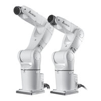
Delta Electronics DRVA1/A4L7 User Manual (131 pages)
Articulated Robot Controller
Brand:
Delta Electronics
| Category:
Robotics
| Size: 6 MB
Table of Contents
Table of Contents
12
Descriptions of Warning Labels
23
Controller Label Locations
23
Figure 1.1 Locations of the Labels in Front of the DCV-2J00 and DCV-2J01 Controller
23
Figure 1.2 Locations of the Labels Behind the DCV-2J00 and DCV-2J01 Controller
23
Figure 1.3 Location of the Label in Front of the DCV-1K02 Controller
24
Figure 1. 4 Location of the High Voltage Warning Label on the Upper Cover
24
Figure 1. 5 Location of the High Voltage Electric Shock and High Temperature Scalding
24
Descriptions of the Controller Product Labels
25
Figure 1.6 Locations of Product Labels
25
Table 1. Descriptions of the 1Sticker Label Names
25
Figure 1.7 Product Label Styles
26
Table 1.2 Descriptions of Product Labels
26
Table 1. 3 Controller Model Number Table
27
Locations of the Robot Sticker Labels
28
Figure 1.8 DRV70/90L7 Sticker Locations
28
Figure 1.9 DRVA1/A4L7 Sticker Locations
28
Figure 1.10 DRVA1/A4LC Sticker Locations
29
Table 1.4 Descriptions of DRV70/90L7, A1/A4L7 and DRVA1/A4LC Sticker Contents
29
Robot Dimensions
31
Figure 1.11 Dimensions of the DRV70L7 Series Robot
31
Figure 1.12 Dimensions of the DRV90L7 Series Robot
32
Figure 1.13 Dimensions of the DRVA1L7 Series Robot
33
Figure 1.14 Dimensions of the DRVA4L7 Series Robot
34
Figure 1.15 Dimensions of the DRVA1LC Series Robot
35
Figure 1.16 Dimensions of the DRVA4LC Series Robot
36
Robot Moving Range
37
Figure 1.17 Moving Range of the DRV70L7 Series Robot
37
Figure 1.18 Moving Range of the DRV90L7 Series Robot
37
Figure 1.19 Moving Range of the DRVA1L7 Series Robot
38
Figure 1.20 Moving Range of the DRVA4L7 Series Robot
38
Figure 1.21 Moving Range of the DRVA1LC Series Robot
39
Figure 1.22 Moving Range of the DRVA4LC Series Robot
39
Controller Specifications
40
Table 2.1 Controller Specifications
40
Figure 2.1 Appearances and Dimensions of the DCV-2J00-AA and DCV-2J01-AA Controllers
41
Figure 2.2 Appearance and Dimensions of the DCV-1K02-AA Controller
41
Transportation and Installation
43
Transportation
43
Transport the Robot and Controller Together
43
Figure 3.1 Images of Fork Type Pallet Truck and Forklift
43
Figure 3.2 Image of Transporting with a Forklift
43
Transporting the Controller Only
44
Transporting the Robot Arm Only
44
Figure 3.3 Hoisting Transportation Method
44
Table 3.1 Angles of each Axis When Moving the Robot
44
Installation
45
Controller Installation
45
Figure 3.4 Robot Moving Posture
45
Figure 3.5 Installation Distance of the DRV Series Controller
45
J6 Flange Installation and Usage Methods
46
Figure 3.6 Cooling Direction of the DCV-1K02-AA Controller's Regenerative Resistor
46
Figure 3.7 Locations of the J6 Flange Blind Holes of the DRV70/90L and DRVA1/A4L7 Series
46
Robot Safety Protection
47
Robot Safety Protection Devices
47
Setting up and Installing Robot Safety Protections
48
Installation of the Emergency Stop Device
48
Figure 4.1 Emergency Stop Button
48
Figure 4.2 Resetting Methods of the Emergency Stop Switch
48
Figure 4.3 Emergency Stop Safe Disconnection Symbol
48
Installation of the Emergency Pull-Rope Switch Device
49
Figure 4.4 Example for Setting up the Safety Pull-Rope Switch
49
Installation of Safety Fences
50
Figure 4.5 Incorrect Installation Height of the Fence
50
Figure 4.6 Example on the Installation of Safety Fence Signals
50
Figure 4.7 Example of Installing Multiple Emergency Stop Devices Outside the Fence
51
Figure 4.8 Example of Installing Multiple Emergency Stop Buttons Inside the Fence
51
Installation of Safety Mat
52
Installation of the Laser Scanner
52
Installation of Safety Gratings
52
Robot Blocking Points
52
Adjusting the Active Blocking Points of DRVA1/A4L7
53
Figure 4.9 Active Blocking Point Position and Working Angle of DRVA1/A4L7- J1 Axis
53
Table 4.1 DRVA1/A4L7-J1 Axis Screw Specifications and Screw Locking Torque
53
Figure 4.10 DRVA1/A4L7-J2 Axis Active Blocking Point Position and Working Angle
54
Table 4.2 DRVA1/A4L7-J2 Axis Screw Specifications and Screw Locking Torque
54
Figure 4.11 DRVA1/A4L7-J3 Axis Active Blocking Point Position and Working Angle
55
Table 4.3 DRVA1/A4L7-J3 Axis Screw Specifications and Screw Locking Torque
55
Adjusting the Active Blocking Points of DRVA1/A4LC
56
Figure 4.12 Active Blocking Point Position and Working Angle of DRVA1/A4LC- J1 Axis
56
Table 4.4 DRVA1/A4LC-J1 Axis Screw Specifications and Screw Locking Torque
56
Figure 4.13 DRVA1/A4LC-J2 Axis Active Blocking Point Position and Working Angle
57
Table 4.5 DRVA1/A4L7-J2 Axis Screw Specifications and Screw Locking Torque
57
Figure 4.14 DRVA1/A4LC-J3 Axis Active Blocking Point Position and Working Angle
58
Table 4.6 DRVA1/A4LC-J3 Axis Screw Specifications and Screw Locking Torque
58
Wiring
59
Composition of the Systems Around the Controller
59
Figure 5.1 Composition of the Peripheral Systems of the DCV-2J00-AA and DCV-2J01-AA Controllers
59
Descriptions of the Controller Interfaces
60
Figure 5.2 Composition of the Peripheral Systems of the DCV-1K02-AA Controller
60
Figure 5.3 DCV-2J00-AA and DCV-2J01-AA Controller Interface
60
Figure 5.4 Controller Interface of DCV-1K02-AA
61
Power Input
62
Figure 5.5 DCV-2J00-AA and DCV-2J01-AA Power Input Terminal Block Location
62
Figure 5.6 DCV-1K02-AA Power Input Terminal Block Location
62
Table 5.1 Controller Power Cable Specifications
62
Figure 5.7 Power Terminal Block Wiring
63
Figure 5.8 Adding Filter and Reactor to the Controller Configuration
63
Robot Connection
64
Figure 5.9 Robot Cable Connection
64
Figure 5.10 Robot Connector Location
64
Figure 5.11 Robot Cables
64
Table 5.2 DRV70/90/A1/A4L7 Robot Cable Pin Definitions
65
Table 5.3 DRVA1/A4LC Robot Cable Pin Definitions
65
External Encoder
66
Figure 5.12 External Encoder Connection Location
66
Table 5.4 External Encoder Connector Pin Definition Table
66
User Output Input Connector
67
Figure 5.13 User. DI/O Connector Location
67
Table 5.5 User. DI/O Connector Pin Definition Table
67
Figure 5.14 NPN Wiring for User. DI Using the Power of the Controller Itself
68
Figure 5.15 PNP Wiring for User. DI Using the Power of the Controller Itself
68
Figure 5.16 User. DI Uses the Power of the Upper Level Controller with NPN Connection
68
Figure 5.17 User. DI Uses the Power of the Upper Level Controller with PNP Connection
69
Figure 5.18 User. DO Uses Controller Voltage Output with NPN Wiring
69
System Digital Output Input Connector
70
Figure 5.19 System Output Input Connector Location
70
Figure 5.20 System. DI Uses the Power of the Controller Itself with NPN Wiring
70
Table 5.6 System. DI/O Pin Definitions
70
Figure 5.21 System. DO Uses the Power of the Controller Itself with NPN Wiring
71
Table 5.7 Operation Mode Selection Table
72
Table 5.8 Run/Pause/Stop Selection Table
73
Table 5.9 Project Operating Status Output Table
74
Safety Connector
75
Figure 5.22 Safety Connector Location
75
Table 5.10 Safety Connector Pin Definitions
75
Table 5.11 DCV-1K02 Safety Connector Cable Color Table
76
Figure 5.23 Robot Emergency Stop Operationssequence Diagram
77
Figure 5.24 Correct Wiring Example of a Single Emergency Stop Button
77
Figure 5.25 Incorrect Wiring Method with a Single NC Emergency Stop Signal
77
Figure 5.26 Wiring Example for Multiple Emergency Stop Buttons
78
Figure 5.27 Wiring Diagram of Multiple Safety Protection Device Signals
78
Figure 5.28 Safety Door Lock Switch
79
Figure 5.29 Wiring for Electromagnetic Safety Switch
79
DC Output Connector
80
Figure 5.30 Schematic Diagram for the Wiring of Pressure Pad, Grating or Laser Scanner
80
Figure 5.31 DCV-1K02-AA Safety Reset Wiring Diagram
80
Teach pendant
81
Figure 5.32 DC Output Connector Location
81
Figure 5.33 Teach pendant Connection Location
81
Table 5.12 Definitions of the DC Output Connector Pins
81
Figure 5.34 Correct Holding Method of the Teach pendant
82
Figure 5.35 DTV Series Teach pendant Interface Structure
83
Figure 5.36 Teach pendant Installation Location
83
Serial Transmission (RS-232, RS-485)
84
Figure 5.37 RS-232/485 Connector Location
84
Table 5.13 Controller RS-232 and RS-485 Pin Definitions
84
Communication Port (Ethernet)
85
Communication Port (Dmcnet)
85
Figure 5.38 Ethernet Communication Port Location
85
Figure 5.39 Dmcnet Communication Port
85
Figure 5.40 Dmcnet Connection Icon
86
Figure 5.41 ASD-DMC-RM32MN
87
Figure 5.42 ASD-DMC-RM32NT
87
How to Turn off the Power
88
Figure 5.43 ASD-DMC-RM32PT
88
Figure 5.44 Turn off the Controller Power
88
Precautions for Installing the Robot Cable Inside the Drag Chain
89
Figure 5.45 Locking Method of the Fuse-Less Switch Power
89
Figure 5.46 Schematic Diagram of the Drag Chain Bending Radius
89
Figure 5.47 Installation and Placement of Drag Chains with Multiple Cables Inside
90
Figure 5.48 Installation Placement Distance of Drag Chains with Multiple Cables Inside
90
Figure 5.49 Installation and Placement of Drag Chains with Multiple Cables Inside
90
Figure 5.50 Installation and Placement of Partition Boards in Drag Chains with Multiple Cables Inside
91
Figure 5.51 the Bending of Cables with Different Lengths Inside the Drag Chain
91
Figure 5.52 Cable Statuses Inside the Drag Chain
91
Figure 5.53 Fixing Method of the Cables Inside the Drag Chain
92
Figure 5.54 Incorrect Tying of Multiple Cables
92
Figure 5.55 Use Partition Boards to Separate the Installation of the Cables and Hoses Inside the Drag Chain
92
Descriptions of the Robot Components
93
Figure 6.1 Locations of the Various Axes of DRV70/90L7
93
Figure 6.2 Locations of the Various Axes of DRVA1/A4LC
93
Robot Operating Direction
94
DRV70/90L7 and DRVA1/A4L7 Air Hoses and Signal Connectors
94
Figure 6.3 Movement Direction of the Various Axes of the DRV Series Robot
94
Figure 6.4 DRV70/90 and A1/A4L7 Series Robots Signal Connector Locations
95
Figure 6.5 Air Hose Bursting Pressure Table
95
Figure 6.6 Solenoid Valve Functions - 5/3-Way Locked in Neutral Position
96
Figure 6.7 Wiring Location of the Solenoid Valve Connector Built in the DRV70/90L7 Series Robot
96
Figure 6.8 Wiring Location of the Solenoid Valve Connector
97
Figure 6.9 Robot Solenoid Air Hose Input Location
97
Figure 6.10 Wiring Example for the Air Hose and Sensor
98
Table 6.1 Robot End Solenoid Valve Signals and Pin Definitions
98
Figure 6.11 Locations of the Base Signal and Solenoid Valve Gas Source
99
Figure 6.12 Locations of the DRVA1/A4L7 Series Robot Base Signal and Solenoid Valve
99
DRVA1/A4LC Air Hose, Signal and Force Release Brake Connectors
100
Figure 6.13 Wiring Example of Controller Providing the 24Vdc to Drive the Solenoid Valve
100
Figure 6.14 Location of the DRVA1/A4LC Base Robot End Signal Connector
100
Figure 6.15 Location of the 12Pos Signal Built in DRVA1/A4LC
101
Figure 6.16 DRVA1/A4LC Client End 12Pos Signal Connector Pin Definitions
101
Table 6.2 DRVA1/A4LC Client End Signal Connector 12Pos Pin Definitions
101
Figure 6.17 Location of the DRVA1/A4LC Air Hose
102
Figure 6.18 DRVA1/A4LC Force Release Brake Connector Robot End Location
102
Figure 6.19 DRVA1/A4LC Force Release Brake Connector Robot End Pin Definition
102
Table 6.3 DRVA1/A4LC Force Release Brake Connector Client End Pin Definition
102
Robot Heavy Duty Connector
103
Figure 6.20 DRVA1/A4LC Force Release Brake Connector Client End Pin Definition
103
Figure 6.21 DRVA1/A4LC Force Release Brake Wiring Diagram
103
Figure 6.22 Location of the Robot's Heavy Duty Connector
104
Figure 6.23 Robot Heavy Duty Connector Cable
104
Figure 6.24 Reserve Space Behind the Base of the Robot
104
Robot Battery Location
105
Figure 6.25 DRV70/90L7 Battery Location
105
Figure 6.26 DRVA1/A4L7 Battery Location
105
Figure 6.27 DRVA1/A4LC Battery Location
106
Quick Wiring
107
Quick Wiring Sequence
107
Figure 7.1 Wiring for the Emergency Stop Button and Safety Signal for DCV-2J00-AA and DCV-2J01-AA
107
Figure 7.2 Wiring for the Emergency Stop Button and Safety Signal for DCV-1K02-AA
108
Figure 7.3 Handheld Teach pendant Connection Method
108
Figure 7.4 Example of Manual Operating Quick Wiring
109
Table 7.1 Operation Mode Selection
109
Figure 7.5 Power Input Wiring Quick Wiring Example
110
Figure 7.6 Power on
110
System DI/O Wiring Example
111
Figure 7.7 Quick Wiring Example for DCV-2J00-AA and DCV-2J01-AA
111
Figure 7.8 DCV-1K02-AA Quick Wiring Example
112
Figure 7.9 Quick Wiring Example for the System DO Using Power NPN of the Controller
113
User DI/O Wiring Example
114
Figure 7.10 User DI/DO Quick Wiring Example Using NPN Method
114
Accessories
115
Accessory Package
115
Table 8.1 DCV-2J00-AA and DCV-2J01-AA Controller Accessory Package Contents Table
115
Table 8.2 DCV-1K02-AA Controller Package Content List
116
Table 8.3 Accessory Package Contents Table of the DRVA1/A4LC Robot
116
Controller Optional Peripherals
117
Filter
117
Figure 8.1 Delta Filter EMF023A21A Dimensions
117
Table 8.4 EMI Filter Specifications
117
Handheld Teach pendant
118
Robot Cable
118
Figure 8.2 Handheld Teach pendant
118
Figure 8.3 DRV70/90L7 and DRVA1/A4LC Robot Cable Icon
118
Table 8.5 Handheld Teach pendant Options List
118
Table 8.6 DRV70/90L7 and DRVA1/A4L7 Robot Cable Specifications and Order Part Number
118
Signal Cable
119
Figure 8.4 DRVA1/A4LC Robot Cable Icon
119
Figure 8.5 DRV70/90L7 and DRVA1/A4L7 Robot Signal Extension Cord
119
Table 8.7 DRVA1/A4LC Robot Cable Specifications and Order Part Number
119
Table 8.8 DRV70/90L7 and DRVA1/A4L7 Robot Signal Extension Cord Specifications and Order Part Number
119
Table 8.9 DRV70/90L7 and DRVA1/A4L7 Robot Signal Extension Cord Pin Definitions
119
Figure 8.6 Dmcnet Cable
120
Figure 8.7 System. DI/O Extension Cord (3081425800)
120
Table 8.10 Dmcnet Cable Specifications and Order Part Number
120
Table 8.11 System. DI/O Extension Cord (3081425800) Cable Color Chart
120
Figure 8.8 User. DI/O Extension Cord (3081425700)
121
Table 8.12 User. DI/O Extension Cord (3081425700) Cable Color Chart
121
Figure 8.9 DRV70/90L7 and DRVA1/A4L7 Safety Extension Cord (3081735000)
122
Figure 8.10 Ext. Encoder Extension Cord (3081427000)
122
Table 8.13 DRV70/90L7 and DRVA1/A4L7
122
Table 8.14 Ext. Encoder Extension Cord (3081427000) Cable Color Chart
122
Figure 8.11 RS-232/485 Extension Cord (3081427100)
123
Table 8.15 RS-232/485 Extension Cord (3081427100) Cable Color Chart
123
Wiring Saving Module
124
Figure 8.12 System. DI/O Conversion Module
124
Figure 8.13 System. DI/O Conversion Cable
124
Table 8.16 System. DI/O Conversion Module Specifications and Order Part Number
124
Figure 8.14 User. DI/O Conversion Module
125
Figure 8.15 User. DI/O Conversion Cable
125
Table 8.17 User. DI/O Conversion Module Specifications and Order Part Number
125
Figure 8.16 Ext. Encoder Conversion Module
126
Figure 8.17 Ext. Encoder Conversion Cable
126
Table 8.18 Ext. Encoder Conversion Module Specifications and Order Part Number
126
Dmcnet DI/O Module
127
Table 8.19 Dmcnet Module
127
Maintenance
128
Robot Checklist
128
Table 9.1 Robot Checklist
128
Maintenance and Replacement of the Robot Battery
129
Table 9.2 Specification Table for the Lubricants of each Axis Reducer
129
Table 9.3 Battery Specifications
129
Fan Replacement
130
Table 9.4 Cleaning and Replacing Method of the Controller Fan
130
Advertisement
Advertisement
Related Products
Delta Electronics DRVA1/A4LC
Delta Electronics DRV70/90L7
Delta Electronics DRP024V060W1BA
Delta Electronics Series DNM04
Delta Electronics Delphi DNM04S0A0S10NFD
Delta Electronics DVPCOPM-SL
Delta Electronics DIAVH-IPC003105
Delta Electronics DVP06XA-E2
Delta Electronics DTA9696
Delta Electronics DVP-MC Series
Delta Electronics Categories
Power Inductor
Power Supply
Computer Hardware
Fan
Transceiver
More Delta Electronics Manuals
Login
Sign In
OR
Sign in with Facebook
Sign in with Google
Upload manual
Upload from disk
Upload from URL