Sign In
Upload
Manuals
Brands
Delta Manuals
Controller
DVP48ES300R
Delta DVP48ES300R PLC Controller Manuals
Manuals and User Guides for Delta DVP48ES300R PLC Controller. We have
1
Delta DVP48ES300R PLC Controller manual available for free PDF download: Operation Manual
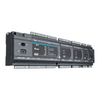
Delta DVP48ES300R Operation Manual (411 pages)
Brand:
Delta
| Category:
Controller
| Size: 10.8 MB
Table of Contents
Revision History
3
Table of Contents
3
Chapter 1 Product Introduction
14
Overview
14
Related Manuals
14
Models Descriptions
14
Overview
19
Characteristics
20
2 Chapter 2 Specifications and System
27
General Specifications
28
CPU Module Specifications
29
Functional Specifications
29
Electrical Specifications
30
CPU Module Profiles
32
CPU Module Input/Output Terminals
33
Digital Input/Output Module Specifications
36
General Specifications
36
Digital Input/Output Module Profiles
38
Digital Input/Output Module Terminals
39
Analog Input/Output Module Specifications
42
General Specifications
42
Analog Input/Output Module Profiles
46
Analog Input/Output Terminals
47
Analog Input/Output Module Terminals
47
Temperature Measurement Modules Specifications
48
General Specifications
48
Temperature Measurement Module Profiles
50
Temperature Measurement Module Dimensions
51
Temperature Mesurement Module Terminals
52
Extension Cable Interface Module Specifications
53
General Specifications
53
Extension Cable Interface Module Profiles
53
Installation and Wiring
54
Chapter 3 Installing Software
55
Installing and Uninstalling Ispsoft
56
Installing Ispsoft
57
Uninstalling Ispsoft
61
Installing and Uninstalling COMMGR
63
Installing COMMGR
63
Uninstalling COMMGR
66
4 Chapter 4 Installing Hardware
67
DVP-ES3 Hardware Framework
69
DVP-ES3 Hardware Component
69
Necessary Components
70
Optional Components
70
Installation
71
Linking the CPU Module and a Module
72
Installation on the Set
73
Notes on Installation
71
Wiring
74
Connecting Power Cables
76
Precautions
76
Ground
76
Wiring Power Supply
77
Power Consumption
78
Wiring CPU Modules
80
Wiring Digital Input Terminals
80
Wiring Digital Output Terminals
83
Wiring RS-485 Terminals
87
Wiring Canopen Terminals
87
Wiring Digital Input / Output Modules
88
Wiring DVP08XM211N
88
Wiring DVP08XN211R
88
Wiring DVP08XN211T
89
Wiring DVP08XP211R
89
Wiring DVP08XP211T
90
Wiring DVP16XM211N
91
Wiring DVP16XN211R
92
Wiring DVP16XN211T
93
Wiring DVP16XP211R
94
Wiring DVP16XP211T
95
Wiring DVP24XP200R
96
Wiring DVP24XP200T
97
Wiring DVP24XN200R
98
Wiring DVP24XN200T
98
Wiring DVP32XP200R
99
Wiring DVP32XP200T
100
Wiring Analog Input / Output Modules
101
Wiring DVP06XA-E2
103
Wiring Temperature Measurement Modules
105
Wiring DVP04PT-E2/DVP06PT-E2
105
Wiring DVP04TC-E2
106
Chapter 5 CPU and Module Devices
107
Introduction to CPU Devices
108
Device Table
108
Basic Structure of I/O Storage
109
Relation between the PLC Action and the Device Type
109
Latched Areas in the Device Range
110
CPU Device Functions
111
Values and Constants
111
Floating-Point Numbers
113
Single-Precision Floating-Point Numbers
113
Decimal Floating-Point Numbers
114
Strings
115
Input Relays (X)
116
Output Relays (Y)
117
Auxiliary Relays (M)
117
Special Auxiliary Relays (SM)
117
Flags (S)
118
Timers (T)
118
Counters
120
32-Bit Counters (HC)
122
Data Registers (D)
124
Special Data Registers (SR)
124
Index Register (E)
124
File Registers (FR)
124
Module Device Functions
125
DVP04AD-E2 Control Registers
125
DVP06XA-E2 Control Registers
134
6 Chapter 6 Writing a Program
151
Quick Start
152
Example
152
Hardware
152
Program
153
Procedure for Creating a Project in Ispsoft
153
Creating a Project
154
Hardware Configuration
155
Configuring a Module
155
Setting the Parameters
156
Creating a Program
157
Adding a Ladder Diagram
157
Basic Editing ─ Creating a Contact and a Coil
159
Basic Editing ─ Inserting a Network and Typing an Instruction
162
Basic Editing ─ Selection of a Network and Operation
164
Basic Editing ─ Connecting a Contact in Parallel
167
Basic Editing ─ Editing a Comment
168
Basic Editing ─ Inserting an Applied Instruction
169
Basic Editing ─ Creating a Comparison Contact and Typing a Constant
171
Writing a Program
172
Checking and Compiling a Program
173
Testing and Debugging a Program
174
Creating a Connection
174
Downloading a Program and Parameters
177
Connection Test
178
Setting a Real-Time Clock
186
Chapter 7 Memory Card
187
Overview of Memory Cards
188
Appearances of Memory Cards
188
Memory Card Specifications
188
Before Using a Memory Card
189
Formatting a Memory Card
189
Installing and Removing a Memory Card
189
Memory Card Slot in a CPU Module
189
Installing a Memory Card
190
Removing a Memory Card
190
Memory Card Contents
191
Initializing a Memory Card
191
Folder Structure in a Memory Card
191
Introduction to the CARD Utility
192
Backing up a Project
194
Restoring a Project
199
Restoration Starts Once CPU Is Supplied with Power
203
CPU Error Log
204
Chapter 8 Hardware Configuration and Data Exchange Setups
205
Hardware Configuration Tool for DVP-ES3 Series Modules
206
Introduction of the HWCONFIG Environment
206
Configuring a Module
207
Editing a Comment
207
Setting the Parameters in a DVP-ES3 Series CPU Module
208
Opening the PLC Parameter Setting Window
208
Setting the Basic CPU Parameters
209
Data Exchange
228
Device Settings Dialog Box Descriptions
228
Chapter 9. Ethernet/Ip Specification and Operation
233
Introduction
236
Ethernet/Ip
236
Definitions of Common Network Terms
236
Ethernet Features
237
Delta EIP Architecture
237
EIP Features
238
Installation
238
Ethernet/Ip Device
238
Network Cable Installation
238
Single Port Device
239
Dual Port Device
239
EIP Builder Software
241
Specifications
242
Ethernet Specification
242
Ethernet/Ip Specification
243
Ethernet Communication Port
244
Communication Port Pin Assignment
244
Communication LED Indicator
244
EIP Builder
245
Run the EIP Builder
245
Run the EIP Builder Via an EIP Scanner
245
Set up the IP Address
247
IP Address Types
247
Set the IP Address (Static IP)
247
Set the IP Address (BOOTP/DHCP)
249
Re-Enable BOOTP/DHCP
252
Troubleshooting
254
Error Code Classification
254
Error Codes & How to Fix Them
254
Configuration Errors
254
Application Error
257
Studio 5000 Software Operation
258
Architecture
258
Create a New Project
258
Create a Scanner
260
Create a New Ethernet/Ip Module
260
Connect to a Delta Adapter
262
Import an EDS File
262
Create an Adapter
264
Editing Corresponding Addresses for DVP-ES3
267
Download
268
Data Mapping
269
CIP Object
270
Object List
270
Data Type
271
Identity Object (Class ID: 01 Hex)
274
Message Router Object (Class ID: 02 Hex)
276
Assembly Object (Class ID: 04 Hex)
277
Connection Manager Object (Class ID: 06 Hex)
279
Port Object (Class ID: F4 Hex)
281
TCP/IP Interface Object (Class ID: F5 Hex)
283
Ethernet Link Object (Class ID: F6 Hex)
286
Register (Class ID: 350 Hex)
289
Y Register (Class ID: 351 Hex)
289
D Register (Class ID: 352 Hex)
290
M Register (Class ID: 353 Hex)
291
S Register (Class ID: 354 Hex)
292
T Register (Class ID: 355 Hex)
293
C Register (Class ID: 356 Hex)
294
Chapter 10 Canopen Function and Operation
313
Introduction to Canopen
314
Canopen Function Descriptions
314
The Input/Output Mapping Areas
315
Installation and Network Topology
316
The Dimensions of DVP-ES3 Series PLC
316
Canopen Communication Port
317
Configure the DVP-ES3 Series PLC with HWCONFIG
317
The Canopen Protocol
323
Introduction to the Canopen Protocol
323
The Canopen Communication Object
324
The Predefined Connection Set
329
Data Structure of SDO Request Message
331
Data Structure of EMERGENCY Request Message
335
Example of Sending SDO through the Ladder Diagram
337
Troubleshooting
339
Canopen Network Node State Display
339
Application Example
342
Chapter 11 11 CPU Module Operating Principles
355
CPU Module Operations
356
Procedure
356
I/O Refreshing and Communication Service
357
CPU Module Operating Modes
358
Operating Modes
358
Status and Operation under Different Operating Modes
358
Chapter 12 Troubleshooting
360
Basic Troubleshooting Steps
361
Clear the Error States
361
Troubleshooting SOP
362
System Log
363
ERROR LED Indicators Blinking Rapidly Every 0.2 Seconds
365
ERROR LED Indicators Slow Blinking Every 3 Seconds and Lighting up for 1 Second
365
Other Errors (Without LED Indicators)
365
Seconds
365
The LED RUN and ERROR Indicators Are Blinking Simultaneously Every
365
The RUN and LED Indicators Are Blinking One after Another Every 0.5 Seconds
365
Troubleshooting for Analog Modules (AD/DA/XA) and Temperature Modules (PT/TC)
372
LED Indicators and Error Codes for CPU Modules
373
Chapter 13 Data Tracer and Data Logger
379
Data Tracer
379
About Data Tracer
379
Example
381
Data Logger
382
About Data Logger
382
Related SM Flags and SR Registors
384
Appendix C EMC Standards
401
EMC Standards for an as Series System
401
DVP-ES3 Series System EMC Standards
401
C1.2 Installation Instructions to Meet EMC Standards
403
C1.3 Cables
404
Appendix D Maintenance and Inspection
407
Cautions
407
Daily Maintenance
408
Required Inspection Tools
408
Daily Inspection
408
Periodic Maintenance
410
Required Inspection Tools
410
Periodic Inspection
410
Advertisement
Advertisement
Related Products
Delta DVP48ES300T
Delta DVP-ES2
Delta DVP-SS2
Delta DVP-TP
Delta DVP-15MC Series
Delta DVP15MC11T
Delta DVP32ES311T
Delta DVP32ES300R
Delta DVP64ES300T
Delta DVP64ES300R
Delta Categories
Plumbing Product
Kitchen & Bath Fixtures
Bathroom Fixtures
Saw
Power Supply
More Delta Manuals
Login
Sign In
OR
Sign in with Facebook
Sign in with Google
Upload manual
Upload from disk
Upload from URL