Sign In
Upload
Manuals
Brands
Delta Manuals
Servo Drives
ASD-B2-0421 Series
Delta ASD-B2-0421 Series Manuals
Manuals and User Guides for Delta ASD-B2-0421 Series. We have
1
Delta ASD-B2-0421 Series manual available for free PDF download: User Manual
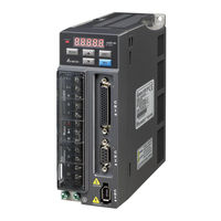
Delta ASD-B2-0421 Series User Manual (345 pages)
Standard AC Servo Drive for General Purpose Applications
Brand:
Delta
| Category:
Servo Drives
| Size: 11.73 MB
Table of Contents
Table of Contents
6
Inspection
14
Nameplate Information
15
Product Model
15
Model Explanation
16
Servo Drive and Corresponding Servo Motor
18
Servo Drive Features
20
Control Modes of Servo Drive
21
Chapter 2 Installation
22
Notes
22
Ambient Conditions of Storage
22
Ambient Conditions of Installation
23
Installation Direction and Space
24
Troubleshooting for the Motor Operation and Status
26
Servo Motor Mounting Directions and Precautions
26
Precautions for Using Oil Seal Servo Motors
27
Precautions for Using Couplings
28
Oil and Water Prevention Measures for the Servo Motor
29
Measures to Suppress Temperature Increase of the Servo Motor
29
Specification of Circuit Breaker and Fuse
30
EMI Filter Selection
31
Selection of Regenerative Resistor
33
Chapter 3 Wiring
40
Connections
40
Connecting to Peripheral Devices
40
Servo Drive Connectors and Terminals
41
Wiring Method
43
Specification of Motor Power Cable
45
Specification of Encoder Connector
47
Selection of Wiring Rod
51
Basic Wiring
53
Included) and Models below
53
750 W Models
54
Kw ~ 3 Kw Models
55
I / O Signal (CN1) Connection
56
I/O Signal (CN1) Connector Terminal Layout
56
Signals Explanation of Connector CN1
58
Wiring Diagrams (CN1)
66
DI and DO Signal Specified by Users
73
CN2 Connector
74
Wiring of CN3 Connector
76
Analog Monitor Output Connector - CN5
77
Standard Connection Example
78
Position (PT) Control Mode
78
Speed Control Mode
79
Torque Control Mode
80
Chapter 4 Panel Display and Operation
82
Panel Description
82
Parameter Setting Procedure
83
Status Display
84
Save Setting Display
84
Decimal Point
84
Alarm Message
84
Positive and Negative Sign Setting
85
Monitor Display
85
General Function
88
Operation of Fault Code Display
88
JOG Mode
89
Force DO Output
90
Digital Input Diagnosis Operation
91
Digital Output Diagnosis Operation
91
Chapter 5 Trial Operation and Tuning
92
Inspection Without Load
92
Applying Power to the Servo Drive
94
JOG Trial Run Without Load
98
Trial Run Without Load (Speed Mode)
99
Tuning Procedure
101
Flowchart of Tuning Procedure
102
Inertia Estimation Flowchart (with Mechanism)
103
Flowchart of Auto Tuning
104
Flowchart of Semi-Auto Tuning
105
Limit of Inertia Ratio
106
Mechanical Resonance Suppression Method
108
Tuning Modes and Parameters
109
Tuning in Manual Mode
110
Chapter 6 Control Modes of Operation
112
Selection of Operation Mode
112
Position Mode
114
Position Command in PT Mode
114
Control Structure of Position Mode
117
Electronic Gear Ratio
119
Low-Pass Filter
121
Gain Adjustment of Position Loop
122
Speed Mode
125
Selection of Speed Mode
125
Control Structure of Speed Mode
126
Smoothing Speed Command
127
The Scaling of Analog Command
131
Timing Diagram in Speed Mode
132
Gain Adjustment of Speed Loop
132
Resonance Suppression
139
Torque Mode
147
Selection of Torque Command
147
Control Structure of Torque Mode
148
Smooth Torque Mode
149
The Scaling of Analog Command
149
Timing Diagram of Torque Mode
151
Dual Modes
152
Speed / Position Dual Mode
152
Speed / Torque Dual Mode
153
Torque / Position Dual Mode
153
Others
154
The Use of Speed Limit
154
The Use of Torque Limit
154
Analog Monitor
155
The Use of Brake
160
Chapter 7 Parameters
162
Parameter Definition
162
Lists of Parameters
163
Parameter Description
173
P0-XX Monitor Parameters
173
P1-XX Basic Parameters
182
P2-XX Extension Parameters
212
P3-XX Communication Parameters
241
P4-XX Diagnosis Parameters
246
Chapter 8 Communications
270
RS-232 Communication Hardware Interface
270
RS-232Communication Parameter Settings
272
MODBUS Communication Protocol
275
Write-In and Read-Out Communication Parameters
287
Chapter 9 Troubleshooting
288
Alarm of Servo Drive
288
Causes and Corrective Actions
291
Corrective Actions after the Alarm Occurs
302
Chapter 10 Specifications
307
Torque Features (T-N Curves)
315
Overload Features
317
Dimensions of Servo Drives
319
Dimensions of Servo Motors
323
Advertisement
Advertisement
Related Products
Delta ASD-B2-0121-F
Delta ASD-B2-0221-F
Delta ASD-B2-0421-F
Delta ASD-B2-0721-F
Delta ASD-B2-0121 Series
Delta ASD-B2-0221 Series
Delta ASD-B2-0721 Series
Delta ASD-B2-1521-F
Delta ASD-B2-1021-F
Delta ASD-B2-1021 Series
Delta Categories
Plumbing Product
Kitchen & Bath Fixtures
Bathroom Fixtures
Saw
Power Supply
More Delta Manuals
Login
Sign In
OR
Sign in with Facebook
Sign in with Google
Upload manual
Upload from disk
Upload from URL