Sign In
Upload
Manuals
Brands
degdrive Manuals
Inverter
DGI500-4T5000G
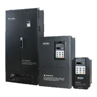
degdrive DGI500-4T5000G Inverter Manuals
Manuals and User Guides for degdrive DGI500-4T5000G Inverter. We have
1
degdrive DGI500-4T5000G Inverter manual available for free PDF download: User Manual
degdrive DGI500-4T5000G User Manual (284 pages)
Universal inverter
Brand:
degdrive
| Category:
Inverter
| Size: 3 MB
Table of Contents
Table of Contents
3
Safety Information and Use Notice Points
7
Safety Precautions
7
Application Range
9
Use Notice Points
9
Scraping Handling Notice
10
Inverter Type and Specification
11
Incoming Inverter Inspect
11
Type Explanation
11
Inverter Type Explanation
12
Appearance and Parts Name Explanation
13
Outer Size
14
DGI500 Optional Base
16
Outer Size of Keypad and Its Fixing Box
18
Product Technic Index and Spec
19
Installation and Wiring
22
Installation Ambient
22
The Demands for Installation Ambient
22
Installation Direction and Space
22
Parts Disassembly and Installation
23
Keyboard Disassembly and Installation
23
Cover Disassembly and Installation
23
Wiring Notice Points
24
Main Loop Terminal Wiring
25
Connection between Inverter and Fitting Parts
27
Main Loop Terminal Wiring
28
Basic Running Wiring Diagram
31
Control Loop Collocation and Wiring
31
Relative Location and Function for Control
31
Board Terminal and Slide Switch
31
Descriptions for Control Board Terminal
33
Analog Input&Output Terminal Wiring
35
Digital Input Terminal Wiring
36
Communication Terminal Wiring
38
Emc(Electromagnetic Compatibility)Explanation
40
Noise Interference Restraining
40
Interference Noise Type
40
Basic Countermeasure for Restrain Interference
41
Field Wiring and Earth Grounding
42
Leak Current and Countermeasure
42
Installation Demand for Electromagnetic On-Off Electronic Device
43
Noise Filter Installation Instructions
43
Run and Operation Explanation for Inverter
44
Run of Inverter
44
Running Order Channels
44
Frequency-Provision Channel
44
Work State
45
Run Mode
46
Operation and Use of Key Board
48
Keypad Layout
48
Keypad Function Description
48
LED and Indicator Light
49
Key Board Display Status
49
User Management Parameters
52
Method for Operating Keypad
52
Inverter Electrification
55
Check before Electrification
55
First Electrification
55
Function Parameter Schedule Graph
56
Symbol Description
56
Detailed Function Specification
99
System Parameter Group: F00
99
Basic Run Function Parameter Group:f01
108
Start, Stop, Forward/Reverse, Brake Function Parameter Group: F02
117
V/F Control Parameter Group: F03
123
Auxiliary Running Parameter Group: F04
125
Communication Control Parameter Group: F05
131
Setting Curve Parameter Group: F06
136
Analog Quantity, Pulse Input Function Parameter Group: F07
139
On-Off Input Function Parameter Group: F08
143
Switch Output Function Parameter Group: F09
158
Simple Plc/Multi-Speed Function Parameters Group:f10
170
Closed-Loop PID Operation Parameters Group:f11
176
Constant Pressure Water Supply Function Parameters Group: F12
183
Traverse, Fixed-Length Control Function Parameters Group: F13
186
Vector Control Parameters Group: F14
190
Motor Parameters Group: F15
196
Closed-Loop Encoder Parameters Group: F16
198
Reserved Parameters Group1:F17
202
Enhanced Control Functions Parameters Group: F18
203
Protective Relevant Function Parameters Group:f19
208
Internal Virtual Input Output Node Parameter Group: F20
219
Reserved Parameter Group 2:F21
221
Reserved Parameter Group 3:F22
221
Reserved Parameter Group 4:F23
221
Reserved Parameter Group 5:F24
221
User Definition Display Parameter Group: F25
222
Fault Record Function Parameter Group: F26
223
Password and Manufacturer Function Parameter Group: F27
225
Troubleshooting
226
Failure and Countermeasure
226
Failure Record Lookup
231
Failure Reset
232
Alarm Reset
232
Maintenance
233
Routine Maintenance
233
Inspection and Replacement of Damageable Parts
233
Repair Guarantee
234
Storage
235
Appendix A Modbus Communication Protocol
236
Appendix B Free-Port Communication Protocol
250
Appendix C Keyboard
262
Keyboard Selection
262
LED Double-Display Digital Potentiometer Keyboard
262
LCD Keyboard
263
LED Single-Display Keyboard
268
Communication Component
269
Appendix D Communication Extension Card
270
Communication Card Selection
270
PROFIBUS-DP Communication Card
270
Canopen Communication Card
273
Canlink Communication Card
275
Appendix E Universal Encoder Expansion Card
277
Appendix F Integration Expansion Card
280
Appendix G Braking Unit and Braking Resistance
282
Advertisement
Advertisement
Related Products
degdrive DGI500-4T5000P
degdrive DGI500-4T5600P
degdrive DGI500-4T5600G
degdrive DGI500-4T0750G
degdrive DGI500-4T1320P
degdrive DGI500-4T3150G
degdrive DGI500-4T3550P
degdrive DGI500-4T4500P
degdrive DGI500-4T4500G
degdrive DGI500-4T4000P
degdrive Categories
DC Drives
Inverter
More degdrive Manuals
Login
Sign In
OR
Sign in with Facebook
Sign in with Google
Upload manual
Upload from disk
Upload from URL