Sign In
Upload
Manuals
Brands
DDK Manuals
Power Tool
HFC3000II
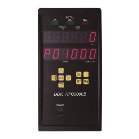
DDK HFC3000II Handheld Nutrunner Manuals
Manuals and User Guides for DDK HFC3000II Handheld Nutrunner. We have
1
DDK HFC3000II Handheld Nutrunner manual available for free PDF download: Instruction Manual
DDK HFC3000II Instruction Manual (216 pages)
Handheld Nutrunner
Brand:
DDK
| Category:
Power Tool
| Size: 4 MB
Table of Contents
Table of Contents
13
Chapter 1 Outline
17
How to Use this Instruction Manual
18
Outline of Functions
19
Usage Precautions
22
Chapter 2 Specifications
23
System Specifications
24
Duty Cycle Calculation
24
Unit Specifications
24
Performance
25
Fastening Performance
25
Controller Unit
25
Model
26
Controller Unit
26
Tools
26
Functions
26
Main Functions
26
Fastening Methods
27
Chapter 3 Part Names
29
Controller Unit Front Panel
30
Bottom Panel SW1 Switch Settings
32
Bottom Panel SW2 Switch Settings
33
Tools
34
Angle Tool
34
Pistol Tool
35
Chapter 4 Installation
37
Installation Procedure
38
Unit Outer Shape and Installation Dimensions
39
Input Power Source Connection
41
Tool Cable Specifications
42
External Control Signal Connection
43
Controller Unit I/O Signals
44
Input Signal: BANK SELECT
46
Input and Output Circuit Specifications and Recommended Connection Circuit
47
Description of I/O Signals
48
Input/Output Signal Timing Chart
57
External Monitoring Device Signal
59
External Monitor Signal Specifications
59
Output Circuit
60
RS232C Interface Signal
61
RS232C Specifications (RS232C-1)
61
RS232C Communication Specifications
61
Data Format (RS232C-1)
62
Ethernet Interface
64
Chapter 5 Power Activation and Operational Tests
65
Items to be Checked before Power Activation
66
Items to be Checked When Activating the Equipment
67
Input Initial Setting Data
68
Items to be Checked after Activation
68
Chapter 6 Description of Operations
69
Controller Unit
70
Tool
72
Between RUN and PROGRAM Modes
73
RUN Mode
74
Changing Modes in the RUN Mode
75
Indications in the RUN Mode(Real Time Mode)
76
Indications in the RUN Mode(Fastening Result Mode)
79
Indications in the RUN Mode(Parameter Setting Mode)
82
Indications in the RUN Mode(System Setting Mode)
83
Indications in the RUN Mode(Operation View)
84
PROGRAM Mode
87
Changing Modes in the PROGRAM Mode
87
Indications in the PROGRAM Mode(Set Value Selection Mode)
88
Indications in the PROGRAM Mode(Set Value Editing Mode)
90
Copying of Parameters/Erasure of the Fastening Result Record
92
Fastening NG (Failure) Result Indications
94
Example of Fastening NG Item Indication
95
NG Judgment
97
Fastening Speed and Time
105
Parameter Structure
107
System Parameters
108
Fastening Parameters
123
Chapter 7 Troubleshooting
151
Abnormal State Display
152
Abnormality Details/Causes and Recovery Methods
153
A.01:Torque Transducer Error
153
A.02:Unused
153
A.03:TOOL ID Error
154
A.04:System Memory Error
155
A.05:Servo Reply Error
155
A.06:Servo Type Error
156
A.07:Unused
156
A.08:Servo Amplifier Error
156
A.09:Setting Data Error
158
Spindle Judgment: Checking the Contents of the REJECT
159
Ethernet Communication
160
Rtc
162
Chapter 8 Options
163
Compactflash
164
Selection Criteria
165
Cf Access Led
165
Storing Data in the CF Card
166
Flow of Data Storage
167
Checking the Capacity of the CF Card
169
Formatting the CF Card
170
Expansion RS232C Interface
171
ID Data Input Setting
172
Chapter 9 External Interface
175
Common Specifications
176
Fieldbus I/O Signal Specifications
176
Message Output Format (Handheld Tool Output → PLC Input)
180
Fieldbus Setup
182
Ethernet/Ip
183
System Structure
183
Description of the Hardware
184
I/O Signal Specifications
185
Fieldbus Setup
185
CC-Link
186
System Structure
186
Description of the Hardware
187
I/O Signal Specifications
189
Fieldbus Setup
190
MELSEC-Q Series Parameter Setting
191
System Area PLC Handshake
192
Profibus Dp-V1
194
System Structure
194
Description of the Hardware
195
I/O Signal Specifications
197
Fieldbus Setup
197
Devicenet
198
System Structure
198
Description of the Hardware
199
I/O Signal Specifications
201
Fieldbus Setup
201
Profinet Io
202
System Structure
202
Description of the Hardware
203
I/O Signal Specifications
204
Fieldbus Setup
205
Chapter 10 Warranty and Servicing
207
Warranty
208
Warranty Period
208
Scope of Warranty
208
Maintenance
208
Servicing System
209
Appendix List of Tool Models
211
Advertisement
Advertisement
Related Products
DDK Categories
Crimp tool
Cables and connectors
Indoor Furnishing
Power Tool
Tools
More DDK Manuals
Login
Sign In
OR
Sign in with Facebook
Sign in with Google
Upload manual
Upload from disk
Upload from URL