Table of Contents

Summary of Contents for DDK HFC3000II
- Page 1 S0140185-H Ⅱ Ⅱ Original instructions S0140185-H...
- Page 2 DAI-ICHI DENTSU LTD. 1-54-1 Shimoishihara, Choufu-city, Tokyo, 182-0034 Japan TEL:+81-42-440-1465 FAX:+81-42-440-1436 URL:http://www.daiichi-dentsu.co.jp E-mail:sales@daiichi-dentsu.co.jp 690-1 Ohmori, Kani-city, Gifu, 509-0238 Japan TEL:+81-574-62-5865 FAX:+81-574-62-3523 Copyright (C) 2014 DAI-ICHI DENTSU LTD. All Rights Reserved. S0140185-H...
- Page 3 Thank you for purchasing our Handheld Nutrunner. This instruction manual describes the procedures for installation, and handling, and actions to be taken in case of any failure. ◆ This instruction manual shall be delivered to the end user who operates the equipment. ◆...
- Page 4 Introduction Warranty Warranty Period The warranty period of this equipment is 1 year from the date of purchase or the date of delivery to the designated place. Scope of Warranty If a malfunction occurs in the equipment in the state of correct use in accordance with this instruction manual within the warranty period, repair or replacement shall be performed free of charge.
- Page 5 Read all instructions before operating the equipment in order to use this equipment safely and correctly. Prior to use, read this instruction manual carefully and fully understand the equipment functions, safety precautions and instructions. Safety precautions in this manual are ranked as [Warning] or [Caution]. To prevent danger to the user and other persons as well as property damage, the instructions that must be fully observed are marked with the symbols below.
- Page 6 Safety Precautions Warning Do not remove the motors and gear cases of tools. The tool output spindle may rotate and cause injury. Do not repair, disassemble, or modify the equipment. Failure to observe this instruction may cause injury, electric shock, fire, or malfunction. Never operate the equipment where it is exposed to water or near corrosive atmosphere and flammable gases.
- Page 7 Safety Precautions Transportation/Storage Caution Transport the equipment properly according to its weight. Failure to observe this instruction may cause injury and malfunction. The conditions when transporting the equipment by ship are as below. ◆ Ambient temperature: -5°C ~ +55°C (Avoid freezing) ◆...
- Page 8 Safety Precautions Installation/Wiring Caution Install the controller using the specified screws. Failure to observe this instruction may cause malfunction. Use the specified combination of the tool and the controller. Failure to observe this instruction may cause fire and malfunction. The power input parts must be provided with safety measures such as breakers and circuit protectors.
- Page 9 Safety Precautions Operation/Adjustment Caution Never operate the equipment with wet hands. Failure to observe this instruction may cause electric shock. Use the equipment under the following conditions. ◆Ambient temperature: 0°C~+45°C (Avoid freezing) ◆Ambient humidity: 90% RH or lower (Avoid moisture) ◆Atmosphere: Indoors (Avoid direct sunlight) No corrosive gases or flammable gases No oil mist, dust, water, salt, iron powder...
- Page 10 Revision History (1/3) Revision Manual No. Content of revision Page date Aug, 2015 S0140185-A 1st Edition (Supporting V1.000) Added explanation of various FB. Chapter 9 Jan 2016 S0140185-B Updated the photograph of the base P3-3,4-4 P4-20 May 2016 S0140185-C Fixed a description of the RS232C Caution addition P9-14 24A Unit specification addition...
- Page 11 (2/3) Revision date Manual No. Content of revision Page (Continued from previous page) 6-4-3 New Added No.37 P6-11,13 6-4-4 Change termination number of “COUNT / D-No.” P6-14 6-4-5 Change termination number of “COUNT / D-No.” P6-15 6-4-6 Added examples during a fastening operation P6-17 6-5-2 Change termination number of “COUNT / D-No.”...
- Page 12 (3/3) Revision date Manual No. Content of revision Page 8th Edition(V1.309 compatible) P4-10 4-5-2 Delete the description of BATCH SEQ END, CF WARNING Dec. 2018 S0140185-H 4-5-4 (2) Delete the description of BATCH SEQ END, CF WARNING P4-16 6-9-1 (2) Changed the description of SYS-035 *1****. P6-47 9-1-1 (2) Changed the description of BATCH SEQ END, CF WARNING P9-5...
-
Page 13: Table Of Contents
Chapter 1 Outline 1-1 How to Use This Instruction Manual 1-2 Outline of Functions 1-3 Usage Precautions Chapter 2 Specifications 2-1 System Specifications 2-1-1 Duty Cycle Calculation 2-1-2 Unit Specifications 2-2 Performance 2-2-1 Fastening Performance 2-2-2 Controller Unit 2-3 Model 2-3-1 Controller Unit 2-3-2 Tools 2-4 Functions... - Page 14 Table of Contents 4-7 RS-232C Interface Signal 4-25 4-7-1 RS232C Specifications (RS232C-1) 4-25 4-7-2 RS232C Communication Specifications 4-25 4-7-3 Data Format (RS232C-1) 4-26 4-8 Ethernet Interface 4-28 Chapter 5: Power Activation and Operational Tests 5-1 Items to be Checked Before Power Activation 5-2 Items to be Checked When Activating the Equipment 5-3 Input Initial Setting Data 5-4 Items to be Checked After Activation...
- Page 15 Table of Contents 7-3 Spindle Judgment: Checking the Contents of the REJECT 7-4 Ethernet Communication 7-10 7-5 RTC 7-12 Chapter 8 Options 8-1 CompactFlash 8-1-1 Summary 8-1-2 Selection criteria 8-1-3 CF ACCESS LED 8-1-4 Storing Data in the CF Card 8-1-5 Flow of Data Storage 8-1-6 Checking the capacity of the CF card 8-1-7 Formatting the CF Card...
- Page 16 Table of Contents Chapter 10 Warranty and Servicing 10-1 Warranty 10-2 10-1-1 Warranty Period 10-2 10-1-2 Scope of Warranty 10-2 10-1-3 Maintenance 10-2 10-2 Servicing System 10-3 Appendix: List of Tool Models S0140185-H...
-
Page 17: Chapter 1 Outline
Chapter 1 Outline Outline Chapter 1 PAGE 1-1 S0140185-H... -
Page 18: How To Use This Instruction Manual
Chapter 1 Outline 1-1. How to Use This Instruction Manual This manual describes the system structure, specifications, handling method, etc., of the Handheld Nutrunner System. These are described in the following order in this manual: Chapter Items Contents Chapter 1 Outline Description of functions and precautions. -
Page 19: Outline Of Functions
Chapter 1 Outline 1-2. Outline of Functions The Handheld Nutrunner is a flexible fastening tool equipped with a compact, high-performance servomotor developed especially for this product. Like the usual high-performance nutrunner system, it is designed to accommodate various tool models and provide useful functions for fool-proofing, data management, data communication, etc. - Page 20 Chapter 1 Outline ☆ Fastening Result Record Fastening results data are saved in a nonvolatile memory (EEPROM) inside the Unit (approx. 10,000 sets of data). As curve record data, 100 sets of data are stored in the volatile memory (RAM) inside the Unit.
- Page 21 Chapter 1 Outline Function Name Stored Curve Data CF Card *2 User Console Stored Curve Data Stored Curve Stored Reject Stored Storage Content Curve Data Data *3 Curve Data Data Storage Location Each Controller CF Card Storable Records 100 results Storage Format Torque-Angle (540deg) Torque-Angle (180deg)
-
Page 22: Usage Precautions
Chapter 1 Outline 1-3. Usage Precautions To ensure use in the best conditions, please conform to the following instructions. ☆ Handling of tool Each tool is designed to fully withstand vibrations and shocks that may be generated during ordinary fastening operation. However, it cannot bear a strong impact that may occur when the tool is dropped or collides against another tool (there is a possibility of breakage of the tool). -
Page 23: Chapter 2 Specifications
Chapter 2 Specifications Chapter 2 Specifications PAGE 2-1 S0140185-H... -
Page 24: System Specifications
Chapter 2 Specifications 2-1. System Specifications Single-phase 100 to 240V AC ±10% Voltage (5m cable for 125V AC provided as accessory) Power Source Frequency 50/60Hz No vibration must be applied directly to the Unit. Installation environment Forced-cooling equipment or heating equipment is required when using the Unit outside the following operating range. -
Page 25: Performance
Chapter 2 Specifications 2-2. Performance 2-2-1. Fastening Performance From 1/2 to Calibration torque 3σ/: 5% or less From 1/4 to 1/2 Calibration torque Torque precision 3σ/ : 6% or less (Precisions in case of in-house standard fastening. *May differ according to work.) Angle display minimm unit 0.1 degree Angle internal control unit... -
Page 26: Model
Chapter 2 Specifications 2-3. Model 2-3-1. Controller Unit HFC-B0**-*-*-*-* N:Option4 nothing EN:EtherNet N:Option3 nothing CF:CF Card(RS232C-2) N:Option2 nothing IO:I/O terminal is attached N:Option1 nothing CC:CC-Link DN:DeviceNet PB:ProfiBusDPV1 PI:ProfiNetIO EI:EtherNetI/P 16:16A 24A:24A 2-3-2. Tools Please refer to the appendix. 2-4. Functions 2-4-1. -
Page 27: Fastening Methods
Chapter 2 Specifications 2-4-2. Fastening Method (1) Torque Method (Angle Monitor) Fastening is performed up to a preset standard torque. The fastening operation is performed with the preset torque as the target, and high limit/low limit judgment of the angle value is enabled. The number of fastenings steps is selectable among 1 step, 2 steps, and 3 steps. - Page 28 Chapter 2 Specifications Memo PAGE 2-6 S0140185-H...
-
Page 29: Chapter 3 Part Names
Chapter 3 Part Names Chapter 3 Part Names PAGE 3-1 S0140185-H... -
Page 30: Controller Unit Front Panel
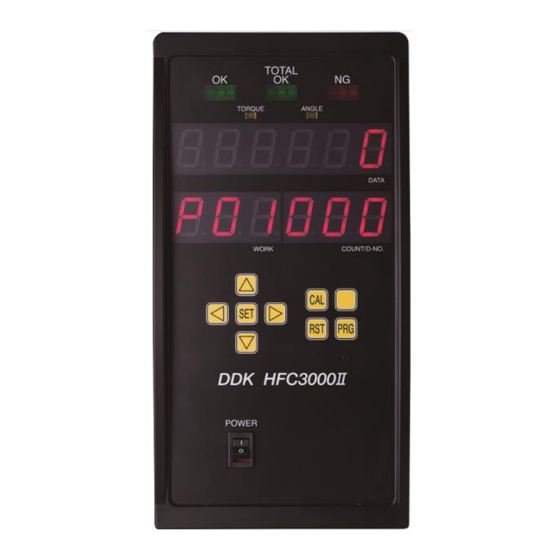
Chapter 3 Part Names 3-1. Controller Unit 3-1-1. Front Panel TOTAL OK OK (ACCEPT) NG (REJECT) Lights up when acceptable (OK) Turns Lights up when the fastening Lights up when even one on when fastening results are obtained results are within the of the preset judgment for the designated number of times. - Page 31 Chapter 3 Part Names 3-1-2. Bottom Panel RS232C-2(Option) ETHERNET(Option) For ID data input For Data Report T/A MON. TOOL Connector for torque and angle Connector for tool cable monitor output connection. connection. (PAGE 4-18) Twist lock type connector. Can be connected and disconnected by twisting by 90 degrees.
-
Page 32: Bottom Panel Sw1 Switch Settings
Chapter 3 Part Names 3-1-3. Bottom Panel SW1 Switch Settings The SW1 switches on the Unit bottom panel are used to set special functions related to fastening. * Be sure to change the SW1 dip switch settings with the power of the Controller Unit being OFF. -
Page 33: Bottom Panel Sw2 Switch Settings
Chapter 3 Part Names 3-1-4. Bottom Panel SW2 Switch Settings The SW2 switches on the Unit bottom panel are used to change settings related to functions of the Unit. * Be sure to change the SW2 dip switch settings with the power of the Unit being OFF Factory Function... -
Page 34: Tools
Chapter 3 Part Names 3-2. Tools 3-2-1. Angle Tool Hand-held type fastening tool provided with angle head, planetary gear, torque transducer, servomotor, indicator LEDs, and operating switches. Tool cable connector ②Reversing switch High-speed servomotor Torque transducer and ①Starting switch planetary gear ③LEDs for judgment and status indications Angle head ①Starting switch: When the switch is turned ON (by pressing), the tool tip rotates for performing... -
Page 35: Pistol Tool
Chapter 3 Part Names 3-2-2. Pistol Tool Pistol type hand-held type fastening tool provided with planetary gear, torque transducer, servomotor, indicator LEDs, and operating switches etc. High-speed servomotor Torque transducer and planetary gear ②Reversing switch ③LEDs for judgment and status indications ①Starting switch Tool cable connector... - Page 36 Chapter 3 Part Names Memo PAGE 3-8 S0140185-H...
-
Page 37: Chapter 4 Installation
Chapter 4 Installation Chapter 4 Installation PAGE 4-1 S0140185-H... -
Page 38: Installation Procedure
Chapter 4 Installation 4-1. Installation Procedure Follow the installation procedures of the Hand System in the order prescribed below. Item Contents Page Mount the Contoller Unit with reference to the outer ① Installation shape. PAGE 4-3 Connection of input power Wiring connection by cable provided as accessory to ②... -
Page 39: Unit Outer Shape And Installation Dimensions
Chapter 4 Installation 4-2. Unit Outer Shape and Installation Dimensions Mounting: 4 points (Rear panel) M6 screws: Use screws with a length equivalent to the installation plate thickness +9mm. Weight: 8.5 kg <Mounting Precautions> ◆ Do not install the unit at a location that is constantly vibrating. ◆... - Page 40 Chapter 4 Installation ●Mounting Conditions ・To enable safe removal of the Controller, install upon securing intervals of 10mm or more. Caution Upper 100mm or more 10mm 10mm more more 250mm or more 250mm or more Lower PAGE 4-4 S0140185-H...
-
Page 41: Input Power Source Connection
Chapter 4 Installation 4-3. Input Power Source Connection Connect the dedicated power cable to the connector at a lower portion of the bottom panel of the Unit. A power cable is provided as standard. Primary power connector PAGE 4-5 S0140185-H... -
Page 42: Tool Cable Specifications
Chapter 4 Installation 4-4. Tool Cable Specifications ■Tool Cable (Cable type: FEB-1616-M**) Cable Length :15m max, Maximum number of relay : 1 Total length L Tool Side Controller side ■Tool Cable (Cable type: C15-F7-M**) Cable Length :15m max, Maximum number of relay : 1 Total length L Tool Side Controller Side... -
Page 43: External Control Signal Connection
Chapter 4 Installation 4-5. External Control Signal Connection DI0 Terminal Block: TB1,2,3 TB3 12 TB3: 12 terminals *The No. 11 terminal at the plug side lacks a projection. TB3 1 TB2 12 TB2: 12 terminals TB2 1 TB1 12 TB1: 12 terminals *The No. -
Page 44: Controller Unit I/O Signals
Chapter 4 Installation 4-5-1. Controller Unit I/O Signals Signal IN/OUT Description of Function/Usage The fastening operation is stopped by setting this signal to “OFF” IN-1 1-1 STOP (A:NO/B:NC) Also, it is possible to change the setting of A contact / B contact. System Parameter:SYS.033[xx1xxx] 0:A contact /1:B contact by setting this signal to “ON”. - Page 45 Chapter 4 Installation (Continued from previous page) Signal IN/OUT Description of Function/Usage 3-1 IN COMMON Common input signal (bipolar) 3-2 +24V DC24V SERVICE POWER SUPPLY 0.5Amax 3-3 GND 3-4 OUT COMMON Common output signal (bipolar) OK count is initialized to 0,and turn off the TB2-9 [BATCH OK] 3-5 BATCH OK RESET IN-13(NO) signal by setting this signal to “ON”...
-
Page 46: Input Signal: Bank Select
Chapter 4 Installation 4-5-2. Input Signal : BANK SELECT The following TB signal names will change according to the output status of TB 1-12 "BANK SELECT". ・Please turn OFF the input signal "BANKSELECT" during fastening operation and when not using bank switching. Caution ·After switching the BANK SELECT signal ON / OFF, wait for 20 msec or more before inputting the output signal. -
Page 47: Input And Output Circuit Specifications And Recommended Connection Circuit
Chapter 4 Installation 4-5-3. Input and Output Circuit Specifications and Recommended Connection Circuit Unit I/O circuit DC power source Input circuit PLC output circuit Input signal Input signal PLC input circuit Output circuit Output signal Output signal *The above diagram shows an NPN type connection example. ・The I/O hardware accommodates both positive and negative polarities and both NPN (sink ・... -
Page 48: Description Of I/O Signals
Chapter 4 Installation 4-5-4. Description of I/O Signals +24V、GND: SERVICE POWER SUPPLY PIN No.: TB3-2,3,11,12 Do not supply power to the [+24V] and [GND] terminals (24V DC service power supply) on the Unit. Doing so may cause damage to the product.Do not use it more than 0.5A. When use the service power supply;... - Page 49 Chapter 4 Installation SELF CHECK: TORQUE TRANSDUCER AUTOMATIC CHECK SIGNAL PIN No.: TB1-6 If this signal is “OFF” (or unconnected) when the START signal is input, the home-position voltage level and the CAL voltage level of the torque transducer are automatically checked before the fastening process.
- Page 50 Chapter 4 Installation (Continued from previous page) WORK WORK WORK WORK WORK WORK WORK SELECT 5 SELECT 4 SELECT 3 SELECT 2 SELECT 1 SELECT 0 PIN No.:TB3-9 PIN No.: TB1-11 PIN No.: TB1-10 PIN No.: TB1-9 PIN No.: TB1-8 PIN No.: TB1-7 OFF(OPEN) OFF(OPEN)
- Page 51 Chapter 4 Installation BATCH OK RESET: BATCH COUNTER RESET SIGNAL PIN No.: TB3-5 When a change of WORK has been selected at the terminal block, the current cycle count value is cleared by input of this reset signal. When a change of WORK has been selected at the Unit indicator panel, the current cycle count value is cleared by input of this reset signal.
- Page 52 Chapter 4 Installation (2) Output Signals When an output signal is “ON,” the voltage at the corresponding output terminal is at the same level as the output common voltage (0V). Depending on the output status of the BANK SELECT signal, the output content of some output pins changes.
- Page 53 Chapter 4 Installation BUSY: SIGNAL DURING FASTENING PIN No.: TB2-5 OUT-5 The “ON” output is performed when the Unit is performing the fastening process. MANREV / RELAY CONTACT-1 SIGNAL PIN No.: TB2-7 OUT-8 RELAY CONTACT –COM SIGNAL PIN No.: TB2-10 Turns ON by manually starting the reversed operation.
- Page 54 Chapter 4 Installation RELAY CONTACT-3 SIGNAL PIN No.: TB2-9 OUT-10 RELAY CONTACT –COM SIGNAL PIN No.: TB2-10 OK is output when the fastening has been performed for the number of times specified by the cycle count. QL OK RELAY CONTACT-4 SIGNAL PIN No.: TB2-11 OUT-11 QL OK RELAY CONTACT-4 SIGNAL...
- Page 55 Chapter 4 Installation WORK OUTPUT 0 ~ 5: WORK SELECTION INPUT CHECK The input signals, WORK SELECT 0 ~ 5, are returned as they are as the output signals, WORK OUTPUT 0 ~ 5. These are used to confirm matching with the work selection that is input. WORK WORK WORK...
- Page 56 Chapter 4 Installation (Continued from previous page) WORK WORK WORK WORK WORK WORK WORK OUTPUT 5 OUTPUT 3 OUTPUT 2 OUTPUT 1 OUTPUT 0 OUTPUT 4 PIN No.: TB2-6 PIN No.:TB2-1 PIN No.:TB3-8 PIN No.:TB3-7 PIN No.:TB2-5 PIN No.:TB2-4 OFF(OPEN) OFF(OPEN) OFF(OPEN) OFF(OPEN)
-
Page 57: Input/Output Signal Timing Chart
Chapter 4 Installation 4-5-5. Input/output signal timing chart ●Basic control signals(Controller software version V1.304 or later) *1) WORK SELECT requires a response time of 100 msec or more after the READY signal ON is output until the START signal is input. *2) After the fastening operation completes, a waiting time of 200 msec or more is required to input the next START signal. - Page 58 Chapter 4 Installation ●Basic control signals(Controller software version V 1.303 or earlier) ●MANREV signal timing chart Fastening PAGE 4-22 S0140185-H...
-
Page 59: External Monitoring Device Signal
Chapter 4 Installation 4-6. External Monitoring Device Signal External monitor signals are output from the MONITOR connector on the Unit bottom. MONITOR Manufacturer: OMRON Type: Connector plug Model: XM3A-0921 Specifications: D-SUB 9-pin plug, soldered type Type: Connector hood Model: XM2S-0913 Specifications: Inch thread (#4-40), maximum outer diameter of compatible cable: 9φ... -
Page 60: Output Circuit
Chapter 4 Installation How to Calibrate the External Monitoring Device When the CAL switch of the Unit indicator is pressed while “1” is indicated at the D-No. indication part of the indicator in the real time mode, the CAL voltage is output at a potential difference of approximately Δ3.75V from TORQUE OUT and, at the same time, the torque value recognized by the Unit is indicated at the upper indication part. -
Page 61: Rs232C Interface Signal
Chapter 4 Installation 4-7. RS232C Interface Signal 4-7-1. RS232C Specifications (RS232C-1) Manufacturer: OMRON Type: Connector socket Model: XM3D-0921 Specifications: D-SUB 9-pin socket, soldered type Type: Connector hood Model: XM2S-0913 Specifications: Inch thread (#4-40), maximum outer diameter of compatible cable: 9φ RS232C-1 4-7-2. -
Page 62: Data Format (Rs232C-1)
Chapter 4 Installation 4-7-3. Data Format (RS232C-1) The fastening result data are output from the RS232C-1 interface at the end of fastening. The data length of the fastening result data in ASCII format is 79 bytes (corresponding to 79 characters) per single fastening operation. - Page 63 Chapter 4 Installation When the fastening judgment is NG (REJECT) (JDG: Judgment, OCR: Occurrence) ACCEPT COUNT No. CONTORLLER No. WORK No. COUNT 39H 39H PEAK TORQUE FINAL ANGLE 20H 31H SIGN SIGN FINAL TORQUE RATE1 20H 31H 30H 2EH RATE2 SIGN RATE3 30H 2EH...
-
Page 64: Ethernet Interface
Chapter 4 Installation 4-8. Ethernet Interface The Ethernet interface is the TCP/IP Ethernet port dedicated to communication with the HFC3000 ® User Console installed in a PC with Windows A commercially available LAN cable (cross/straight) can be used as the cable. The following factory settings are set as the TCP/IP settings of the Unit. -
Page 65: Chapter 5 Power Activation And Operational Tests
Chapter 5 Power Activation and Operational Tests Chapter 5 Power Activation and Operational Tests PAGE 5-1 S0140185-H... -
Page 66: Items To Be Checked Before Power Activation
Chapter 5 Power Activation and Operational Tests 5-1. Items to be Checked Before Power Activation (1) Check connection between tool and Controller Connect the cable between the tool and the controller securely. If there is a movable part in the path of the cable, check whether or not the cable receives stress by actually moving the movable part. -
Page 67: Items To Be Checked When Activating The Equipment
Chapter 5 Power Activation and Operational Tests 5-2. Items to be Checked When Activating the Equipment Confirm that the indications on the indicator change as follows when the control power is activated. RUN Mode Power activation All segments are lit for approx. -
Page 68: Input Initial Setting Data
Chapter 5 Power Activation and Operational Tests 5-3. Input Initial Setting Data After checking all of the check items of the previous section and activating the power, input the data necessary for performing fastening. Although initial setting data based on the customer’s specifications are input at the time of shipment, if the setting data need to be changed, please refer to “Chapter 6 Description of Operations.”... -
Page 69: Chapter 6 Description Of Operations
Chapter 6 Description of Operations Chapter 6 Description of Operations PAGE 6-1 S0140185-H... -
Page 70: Controller Unit
Chapter 6 Description of Operations 6-1. Controller Unit ②Indication LEDs ③Switches for Data Indication ①Operation/Check Switches Operations (1) Operation/Check Switches ①CAL key switch: CAL voltage check When this switch is pressed, a check of the torque transducer of the tool is performed. The calibration torque value is indicated at the “DATA”... - Page 71 Chapter 6 Description of Operations (2) Indication LEDs ①OK LED Green [QL OK] This lights up when the fastening ends with all results being within the various setting ranges. When the TOTAL OK LED lights up, this LED is OFF. ②NG LED Red [NG] This lights up when the fastening ends with a result falling outside any of the various setting ranges.
-
Page 72: Tool
Chapter 6 Description of Operations 6-2. Tool This is a pistol type hand-held type fastening tool provided with planetary gear, torque transducer, servomotor, indicator LEDs, and operating switches etc. High-speed servomotor Torque transducer and planetary gear ③LEDs for judgment and status indications ①Starting switch ②Reversing switch... -
Page 73: Between Run And Program Modes
Chapter 6 Description of Operations ③LED for judgment and status indications (4 LEDs): During the fastening operation, all judgment LEDs are OFF. If the fastening result is OK, the green judgment LED lights up. (In the case of TOTAL OK, the green judgment LED flashes slowly.) If the fastening result is NG (failure), the red judgment LED becomes lit (angle-related NG: rapid flashing;... -
Page 74: Run Mode
Chapter 6 Description of Operations 6-4. RUN Mode When the power is activated (turned ON) and the initial process ends, the operation enabled mode (RUN mode) is entered. In the RUN mode, mainly the fastening results, abnormality status, Spindle No., parameters, etc., are indicated. Data Indication Part (RUN Mode) DATA Indication Part COUNT/D-No. -
Page 75: Changing Modes In The Run Mode
Chapter 6 Description of Operations 6-4-1. Changing Modes in the RUN Mode In the RUN mode, selection among the five modes can be performed by pressing the [◄] or [►] switch. Further, in modes other than “Operation View,” the indicated content can be changed by pressing the [▲] or [▼] switch. -
Page 76: Indications In The Run Mode(Real Time Mode)
Chapter 6 Description of Operations 6-4-2. Indications in the RUN Mode(Real time Mode) In the real time mode, [Mon.] is indicated on the WORK Indication Part. The value in the COUNT/D-No. indication part is incremented or decremented with the [▲] or [▼] switch to change the indicated content. - Page 77 Chapter 6 Description of Operations ● List of Contents Indicated in the Real Time Mode(1/2) COUNT/ WORK DATA Units D-NO [Torque Value Indication] The load that is currently applied to the torque transducer is indicated in real time. When the [CAL] switch is pressed, the torque value converted in terms of the calibration torque is output.
- Page 78 Chapter 6 Description of Operations D-No. 006: External I/O Disabling Function D-No. 7: ZERO/CAL Voltage Error Warning (SW2: Pin No. 6 is ON) AUX. DI (lit up if ON) Batch reset input signal D-No. 006: Simplified I/O Monitor (SW2: Pin No. 6 is OFF) Standard DI (lit up if ON) bit0 ...
-
Page 79: Indications In The Run Mode(Fastening Result Mode)
Chapter 6 Description of Operations 6-4-3. Indications in the RUN Mode(Fastening Result Mode) In the fastening result mode, “r” is indicated at the 100s digit of the WORK indication part and the parameter No. (01 ~ 64) of the fastening operation that was performed is indicated by the 10s and 1s digits. - Page 80 Chapter 6 Description of Operations ● List of Contents Indicated in the Fastening Result Mode(1/2) If a value exceeding (falling below) the upper and lower limits of the tightening parameter is detected during the tightening operation, The DATA display section of COUNT / D - No. 00 to 10 switches the display of the following items and 1STNG items every second.
- Page 81 Chapter 6 Description of Operations ● List of Contents Indicated in the Fastening Result Mode(2/2) COUNT WORK DATA Judgment Unit /D-NO Rate 1 increment torque (torque from start of rate 1 to end of rate 1) N•m Rate 1 increment angle (angle from start of rate 1 to end of rate 1) Rate 2 increment torque (torque from start of rate 2 to end of rate 2) N•m Rate 2 increment angle (angle from start of rate 2 to end of rate 2)
-
Page 82: Indications In The Run Mode(Parameter Setting Mode)
Chapter 6 Description of Operations 6-4-4. Indications in the RUN Mode(Parameter Setting Mode) In the parameter setting mode, “P” is indicated at the 100s digit of the WORK indication part and the parameter No. (01 to 64) is indicated by the 10s and 1s digits. The D-No. indication part is changed by pressing the [▲] or [▼] switch and the content of the data No. -
Page 83: Indications In The Run Mode(System Setting Mode)
Chapter 6 Description of Operations 6-4-5. Indications in the RUN Mode(System Setting Mode) In the system setting mode, “SYS.” is indicated in the WORK indication part. The D-No. indication part is changed by pressing the [▲] or [▼] switch and the content corresponding to No. -
Page 84: Indications In The Run Mode(Operation View)
Chapter 6 Description of Operations 6-4-6. Indications in the RUN Mode(Operation View) In the operation view, the currently selected work (parameter) No. (01 ~ 64) is indicated in the WORK indication part. The Spindle No. of the Unit is indicated by the 10s and 1s digits of the COUNT/D-No. - Page 85 Chapter 6 Description of Operations Also, during the fastening operation, the operation speed and the fastening step state are indicated. In the indication during the fastening operation, the parameter No. (01~ 64) that is currently put in operation is indicated in the WORK indication part. The mode cannot be changed in the indication during the fastening operation.
- Page 86 Chapter 6 Description of Operations When the Work Change setting of the system parameter D-No.034 [System option 2] is "Display Panel" (***** 0), the work number can changed by the [▲], [▼] switches. “WORK” Work No. 01 P 0 1 Work No.
-
Page 87: Program Mode
Chapter 6 Description of Operations 6-5. PROGRAM Mode The parameter settings can be changed in the PROGRAM mode. The Data No. and parameter of each parameter No. are indicated on the indicator. Indicator (PROGRAM Mode) DATA indication part COUNT/D-No. indication part WORK indication part ●DATA indication part The set value (parameter) is indicated. -
Page 88: Indications In The Program Mode(Set Value Selection Mode)
Chapter 6 Description of Operations 6-5-2. Indications in the PROGRAM Mode(Set Value Selection Mode) Immediately after changing to the “Set Value Selection Mode,” the cursor (flashing number) is indicated in the WORK indication part when the [◄] switch is pressed and is indicated in the COUNT/D-No. - Page 89 Chapter 6 Description of Operations In the set value selection mode, “SYS.” is indicated in the WORK indication part in the case of a system parameter and the parameter No. (01 to 64) is indicated in the WORK indication part in the case of a fastening parameter.
-
Page 90: Indications In The Program Mode(Set Value Editing Mode)
Chapter 6 Description of Operations 6-5-3. Indications in the PROGRAM Mode(Set Value Editing Mode) Immediately after changing to the “Set Value Editing Mode,” the cursor (flashing number) is indicated in the upper stage of the indication part. When the [▲] or [▼] switch is pressed, the numerical value at the cursor position changes by ±1. - Page 91 Chapter 6 Description of Operations ●System Parameter Setting Method A parameter with which [SYS] is indicated in the COUNT/D-No. indication part is a system parameter and its set value is changed by editing the set value, then pressing the [SET] switch, thereafter changing the indication of “NO”...
-
Page 92: Copying Of Parameters/Erasure Of The Fastening Result Record
Chapter 6 Description of Operations 6-6. Copying of Parameters / Erasure of the Fastening Result Record In setting the contents of multiple parameter Nos., a certain parameter No. can be copied to another parameter No. in the set value editing mode. Parameters can be copied by the following operation procedures. - Page 93 Chapter 6 Description of Operations Similar operations can be performed from “ErASE,” with “021” indicated in the D-No. indication part, to erase all fastening result record stored in the Unit. ・ Be careful in executing erasing operation because data cannot be recovered after the fastening result record is erased.
-
Page 94: Fastening Ng (Failure) Result Indications
Chapter 6 Description of Operations 6-7. Fastening NG (Failure) Result Indications When a fastening NG occurs, in addition to the NG lamp indication at the upper part of the controller, the item detected as the fastening NG is indicated in the numerical value indication part by the present function. In the case of fastening to the standard torque, judgments are made in the order: rate high/low limits, differential angle high/low limits, 2ND region fastening high/low limit times, angle high/low limits, peak torque high/low limits, and final torque high/low limits, and the item with which NG is detected first is indicated. -
Page 95: Example Of Fastening Ng Item Indication
Chapter 6 Description of Operations 6-7-1. Example of Fastening NG item indication 1. Torque High Limit Judgment High limit peak torque NG Cause: Seizing or locking of the screw Torque inhibit limit NG Cause: Work fault, socket fault 2. Angle High Limit Judgment High limit angle NG Cause: Elongation of screw. - Page 96 Chapter 6 Description of Operations 4. Fastening Time High Limit Judgment High limit 1ST time NG Cause: Tapping fault of object of fastening, bolt thread fault Detachment of socket High limit 2ND time NG Cause: Elongation of bolt Cutting of bolt Detachment of socket 5.
-
Page 97: Ng Judgment
Chapter 6 Description of Operations 6-7-2. NG Judgment Judgments by the high and low limit values of torque, angle, time, and rundown revolutions are performed during the fastening operation or after the end of fastening. The REJECT Spindle judgment is made if a fastening result falls outside the high or low limit range. * High and Low Limit Standard Values for Output Judgment The high and low limit values of the HFC3000 System are as follows. - Page 98 Chapter 6 Description of Operations The following judgments cannot be made unavailable. ・Peak torque check ・Final angle check ・Timeout check Caution ●Torque Check [N•m] •Peak Torque The high and low limit values of the peak torque in the fastening operation are set. The fastening operation is ended when the peak torque high limit value is exceeded during the fastening operation.
- Page 99 Chapter 6 Description of Operations ●Angle Check [deg] •Final Angle The high and low limit values of the angle from the point of Snug torque detection to the end are set. The fastening operation is ended when the angle high limit value is exceeded during the fastening operation.
- Page 100 Chapter 6 Description of Operations ●Rate Check Three rates can be used to monitor the fastening operation during the fastening operation. A rate start torque (angle) and a rate end torque (angle) are set and the torque slope (slope of the torque vs.
- Page 101 Chapter 6 Description of Operations 1.If the rate start torque (angle) cannot be detected during the fastening operation, the rate check will not be performed. 2.Under the following conditions, the torque (angle) at the end of fastening is judged as the rate end torque (angle).
- Page 102 Chapter 6 Description of Operations ● Differential Angle Check After the end of fastening, the differential angle, which is the difference between the seating point (angle) of the final torque and the seating point (angle) calculated from the rate 2, is measured and judged.
- Page 103 Chapter 6 Description of Operations ●Break away Torque Check Whether or not the torque value during reverse rotation is within the high limit ranges is judged. If the torque exceeds the upper limit value, the fastening operation is ended and the abnormal state signal A09-08 “Reverse Torque Error”...
- Page 104 Chapter 6 Description of Operations ●Current Value Warnings After the end of the fastening operation, it is judged whether or not the peak current value during operation is within the high and low limit ranges. If the peak current value during operation falls below the low current limit or exceeds the high current limit, although the Unit outputs the ACCEPT Spindle judgment, the PLC layout output signal “Multi: Current Limit Warning,”...
-
Page 105: Fastening Speed And Time
Chapter 6 Description of Operations 6-8. Fastening Speed and Time With the HFC3000 Nutrunner System, the speed can be set according to the fastening operation. 1. Within the set 1st time high limit value, fastening up to the 1st torque or the 1st angle is performed. Also within the 1st time, the following fastening operations are executed. - Page 106 Chapter 6 Description of Operations (Continued from previous page) 2. When the 1st torque or the 1st angle is detected, the 1st time ends and the 2nd time is started. The 1st torque and the 1st angle are the points of changing from the 1st speed to the 2nd speed and are the points of synchronization of the 2nd step.
-
Page 107: Parameter Structure
Chapter 6 Description of Operations 6-9. Parameter Structure Parameter No. SYS System Parameters 000: Torque Unit 001: Software Version 002: Amplifier Version 003: System Indication 504:Touch Panel number of retries Parameter No. P. 64 Parameter No. P. 63 Parameter No. P. 62 Parameter No. -
Page 108: System Parameters
Chapter 6 Description of Operations 6-9-1. System Parameters Setting Item D-No. Contents change Torque Unit Software Version Amplifier Version System Indication ○ Spindle Adapter Gear Ratio For Adjustment by the Manufacturer For Adjustment by the Manufacturer Communication Spindle Indication Spindle Cycle Count (×1 million) Spindle Cycle Count (×1) Unit Maximum Current ○... - Page 109 Chapter 6 Description of Operations (Continued from previous page) Setting Item D-No. Contents Units change Connected Tool No. Connected Tool Information “015-P1” Connected Tool CAL Torque Decimal Point Position Connected Tool CAL Torque Connected Tool CAL Voltage Connected Tool ZERO Voltage Connected Tool Internal Gear Ratio (×100) Connected Connected Tool Serial No.
- Page 110 Chapter 6 Description of Operations (Continued from previous page) Setting Item D-No. Contents Units change CF Card Storage Capacity RS232C-2 Communication Speed RS232C-2 Parity RS232C-2 Stop Bit RS232C-2 Word Length Not use Not use Option Information2 Not use Not use ID Input Selection Add STX, ETX External Input Select...
- Page 111 Chapter 6 Description of Operations Unit Information 1 SYS.000 Torque Unit Cannot be changed. All fastening parameters within the Unit will have the same torque unit. SYS.001 Software Version Cannot be changed. This is the software version of the Unit. SYS.002 Amplifier Version Cannot be changed.
- Page 112 Chapter 6 Description of Operations SYS.010 Unit Maximum Current Cannot be changed This indicates the maximum current value of the Unit. SYS.011 IP Address (upper 6 digits) SYS.012 IP Address (lower 6 digits) Setting range: 0 ~ 255 The IP address is set here. SYS.013 Subnet Mask (upper 6 digits) SYS.014 Subnet Mask (lower 6 digits) Setting range: 0 ~...
- Page 113 Chapter 6 Description of Operations SYS.026 Unit SW1 Setting State SYS.027 Unit SW2 Setting State The setting states of the switch on the Unit (the SW1 and the SW2 switch on the Unit bottom panel) are indicated. D-No.026 D-No.027 The ON/OFF states of SW No. 1 ~ No. 8 are indicated in 8-bit hexadecimal code in the part in which “00H”...
- Page 114 Chapter 6 Description of Operations Options SYS.030 Setting Change Unlock Code Standard setting: 000000 Restrict the setting so that it can not be changed directly from the controller. When a value other than the standard setting is set, changing the controller to the PROGRAM mode displays the numeric value input screen.
- Page 115 Chapter 6 Description of Operations SYS.035 System Option 3 Standard setting: 000000 An optional function of the Unit is set here. *****1: Prohibition of Resume after Total Accept Relay (0: OFF./1: ON). ・Set to “1” if restart is to be prohibited when the TOTAL-OK state is entered. Even if Spindle judgment is REJECT (NG), the next fastening start can not be performed before the Controller software version 1.300.
- Page 116 Chapter 6 Description of Operations Connected Tool Settings SYS.100 Connected Tool No. The tool No. corresponding to the tool model is indicated. Please refer to “Tool Models.” SYS.101 Connected Tool Information The maximum torque and motor capacity of D-No. 100 “Connected Tool No.” are indicated. SYS.102 Tool CAL Torque Decimal Point The decimal point position of the torque value of D-No.
- Page 117 Chapter 6 Description of Operations Unit Information 2 SYS.200 Unit Setup Tool No. Setting range: Tool No. registered for the model The Tool No. of the connected tool is set with reference to “Tool Models.” When the unit setup tool No. is changed, initialization and automatic correction of the fastening parameter set values are performed.
- Page 118 Chapter 6 Description of Operations Option Information 1 SYS.300 Connected Fieldbus Information The type of fieldbus installed on the fieldbus port is indicated. Fieldbus unset (Standard IO) MFC-CC Installed (CC-Link) MFC-PB Installed MFC-DN (PROFIBUS Installed DP-V1) (DeviceNet) MFC-EN Installed MFC-PN Installed (EtherNet/IP) (PROFINET IO) SYS.301 ANYBUS-CC Version (besides standard IO)
- Page 119 Chapter 6 Description of Operations PROFIBUS PROFINET SYS.300 CC-Link DeviceNet EtherNet/IP DP-V1 ○ ○ ○ SYS.303 ○ ○ SYS.304 ○ SYS.305 ○ SYS.306 ○ ○ ○ ○ ○ SYS.307 ○ ○ ○ ○ ○ SYS.308 ○ ○ ○ ○ ○ SYS.309 ○...
- Page 120 Chapter 6 Description of Operations SYS.309 Message Block Byte Length [byte] (besides standard IO) The message block byte length of the fieldbus set in the Unit is indicated. Fieldbus type CC-Link DeviceNet PROFIBUSDP-V1 PROFINET IO EtherNet/IP 144byte 250 byte 64 byte 250 byte 250 byte SYS.310 Message Setting Byte Length “PLC →...
- Page 121 Chapter 6 Description of Operations Option Information 2 SYS.400 CF Card Storage Capacity [MB] The storable capacity of the CF card is indicated. (Units are displayed as "%" in Controller Software Version 1.209 or earlier) SYS.401 RS232C-2 Communication Speed [bps] The communication speed of the RS232C-2 interface is indicated.
- Page 122 Chapter 6 Description of Operations Touch Panel SYS.500 IP Address (upper 6 digits) SYS.501 IP Address (lower 6 digits) Setting range: 0 ~ 255 The IP address of the touch panel connected in the Unit is indicated. SYS.502 Touch Panel Function / Language Setup standard setting : 0 Setting range : 0~4 Disabling/enabling of the touch panel function and the language setting are changed.
-
Page 123: Fastening Parameters
Chapter 6 Description of Operations 6-9-2. Fastening Parameters <Fastening Parameters> * Items in colored cells are skipped by the indicator. Torque Angle Item D-No. Contents Method Method Fastening Method ○ ○ Fastening Steps ○ ○ Fastening Option Fastening ○ ○ Judgment Item 1 Settings ○... - Page 124 Chapter 6 Description of Operations (Continued from previous page) Torque Angle Item D-No. Contents Method Method ○ ○ Rate 1 Low Limit ○ ○ Rate 1 High Limit ○ ○ Rate 2 Low Limit ○ ○ Rate 2 High Limit ○...
- Page 125 Chapter 6 Description of Operations (Continued from previous page) Torque Angle Item D-No. Contents Method Method ○ ○ Number of Accept [times] Others ○ ○ Angle Head Torque Variation Rate[%] ○ ○ CW Servo Lock Time Between Steps ○ ○ CW Wait Time Between Steps ○...
- Page 126 Chapter 6 Description of Operations Fastening Settings D-No.000 Fastening Method Standard setting: 0 The method used for fastening is set. 0: Torque Method, 1: Angle Method D-No. 001 Fastening Steps Standard setting: 1 The number of steps used in fastening is set. 1: 1-Step Fastening ・...
- Page 127 Chapter 6 Description of Operations Be careful as the fastening judgment is not performed regardless of the values of the high and low limit set values when the settings of the fastening parameters Caution D-No. 003 “Judgment Item 1” and D-No. 004 “Judgment Item 2” are 0. D-No.
- Page 128 Chapter 6 Description of Operations D-No. 004 Judgment Item 2 Standard setting: 000001 Only the change 0 → 1 is enabled. *****1: Timeout Check ・ Whether or not the fastening time from the start of fastening to D-No. 105 [1st Torque] or D-No. 205 [1st Angle] or from D-No.
- Page 129 Chapter 6 Description of Operations D-No.005 After Fastening Operation Standard setting: 000000 *****1: 1 Pulse Reverse ・After the end of fastening, the torque is reversed at the D-No. 121 [1 Pulse Reverse Torque High Limit]. The 1 Pulse Reverse is performed at the D-No. 410 [1 Pulse Reverse Speed] for the D-No.
- Page 130 Chapter 6 Description of Operations D-No.006 Interrupt Operation During Fastening Standard setting: 000000 *****1: Pulse Fastening Operation ・Set this to ON if fastening by pulsing is to be performed (pulsing is started after detection of 1ST). ****1*: Gyro Setup Enable ・With a P type or T type or D type tool, the pause operation functions are enabled when this is set to 【...
- Page 131 Chapter 6 Description of Operations Torque D-No. 100 Calibration Torque [N・m] Setting range: 70% ~ 120% of the standard calibration torque of the tool The calibration torque value of the connected tool is set. In a case where a socket or offset gear, with which a load is applied to the tool top, is connected or in a case where, due to the workpiece characteristics, the indicated fastening result value differs from the result obtained by a fastening torque tester, etc., the fastening torque can be corrected by the setting of the calibration torque.
- Page 132 Chapter 6 Description of Operations D-No. 104 Ramp Down Start Torque [N・m] Setting range: 0 ~ D-No. 100 [Calibration Torque] × 1.0 The torque value at which D-No. 401 [Freerun Speed] is switched to D-No. 402 [1st Speed] is set. However, even if the ramp down start torque is not detected, switching to D-No.
- Page 133 Chapter 6 Description of Operations D-No. 110 Reverse Torque High Limit [N・m] Setting range: 0 ~ D-No. 100 [Calibration Torque] × 1.3 The high limit value of the torque during reverse operation is set. When the reverse torque high limit is exceeded during reverse operation, fastening is stopped and the abnormal state signal A.09-08 “Reverse Torque Error”...
- Page 134 Chapter 6 Description of Operations D-No. 118 Final Torque Low Limit [N・m] Setting range: 0 ~ D-No. 100 [Calibration Torque] × 1.1 D-No. 119 Final Torque High Limit [N・m] Setting range: 0 ~ D-No. 100 [Calibration Torque] × 1.3 The low and high limit values of the torque at the end of fastening are set. ・...
- Page 135 Chapter 6 Description of Operations Angle D-No. 200 Final Angle Low Limit [deg] D-No. 201 Final Angle High Limit [deg] Setting range: 0 ~ 9999.9 The low and high limit values of the output judgment angle are set. When the fastening angle exceeds the final angle high limit or falls below the final angle low limit, the REJECT Spindle judgment is made.
- Page 136 Chapter 6 Description of Operations D-No.208 Option [deg] Setting range: 0 ~ 9999.9 *Not used D-No.209 Correction Angle [deg] Setting range: -99.9 ~ 99.9 *Please be sure to use with 0. D-No.211 Option [deg] Setting range: 0.1 ~ 10.0 *Not used PAGE 6-68 S0140185-H...
- Page 137 Chapter 6 Description of Operations Rate D-No. 300 Rate 1 Low Limit [N・m/deg] Setting range: - maximum torque rate of tool ~ maximum torque rate of tool The low limit value of the slope of torque vs. angle between the two points of D-No. 112 [Rate 1 Start Torque] ~ D-No.
- Page 138 Chapter 6 Description of Operations Time D-No. 310 Initial Time [sec] Setting range: 0.0 ~ 999.9 The time for shock relaxation, fitting of the bolt and socket, etc., at the start of fastening is set. Operation at D-No. 400 [Initial Speed] is executed during the initial time or during D-No. 500 [Freerun Revolutions].
- Page 139 Chapter 6 Description of Operations Speed ・ The minimum tool rotation speed and the maximum tool rotation speed differ according to the tool model. Caution Please refer to “Tool Models” regarding the allowed input range. D-No. 400 Initial Speed [rpm] Setting range: Minimum tool rotation speed to maximum tool rotation speed The speed for impact relaxation, fitting of the bolt and socket, etc., at the start of fastening is set.
- Page 140 Chapter 6 Description of Operations D-No.405 Reverse 1 Speed [rpm] Setting range: Minimum tool rotation speed to maximum tool rotation speed The speed during reverse operation is set. This is the reverse speed at which rotation is performed while the REV. switch of the indicator is pressed.
- Page 141 Chapter 6 Description of Operations Revolutions/Current D-No. 500 Freerun Revolutions [rev.] Setting range: 0 ~ 99.9 The number of revolutions, from the start of fastening, at which switching to D-No. 402 [1st Speed] is performed is set. However, even if the freerun revolutions are not reached, switching to D-No. 402 [1st Speed] is performed when D-No.
- Page 142 Chapter 6 Description of Operations Other/Time D-No.540 Number of Accept [times] Setting range: 0~99 This designates the number of times of fastening and when fastening OK is issued for the number of times designated by the cycle count, the batch OK is output. D-No.541 Angle Head Torque Variation Rate [%] Initial value: 0, Setting range: 0~100 When reaching the Standard Torque and the monitored curve variation of the torque curve shows...
- Page 143 Chapter 6 Description of Operations D-No.546 Reverse Ramp Up Time [msec] Setting range: 100~5000, Standard setting: 500 The time constant for acceleration from zero speed to the maximum rotation speed of the tool in reverse rotation operation is set. The reverse ramp up time is used in the following cases. ・Manual reverse by raising (“OFF”→”ON”) of the PLC I/O input signal “REVERSE.”...
- Page 144 Chapter 6 Description of Operations Recovery pulse operation D-No.005 After Fastening Operation: Recovery Pulse ON Set value: xxxx1x D-No.550 Recovery Pulse Count [times] Setting range: 0~50 D-No.551 Recovery Pulse Speed [rpm] Setting range: within tool speed range Setting range:0 ~ 200 D-No.552 Pulse Fastening StopServo Lock Time [msec] Setting range:0 ~...
- Page 145 Chapter 6 Description of Operations (10) Pulsing D-No.006 Interrupt Operation During Fastening : Pulse Fastening Operation ON Set value: xxxxx1 By setting “1” for Pulse Fastening Operation ON as Data No. 006 Fastening Interrupt Operation, the pulse fastening operation is performed from after the detection of the 1st torque (D-No. 105) to the attainment of the standard torque (D-No.
- Page 146 Chapter 6 Description of Operations (11) Gyro D-No.006 Interrupt Operation During Fastening : Gyro Setup Enable ON Set value: xxxx1x By setting “1” for Gyro Settings Available ON as data No. 006 Interrupt Operation During Fastening, a gyro pause operation is performed from after the detection of the 1st torque (D-No. 105) to the attainment of the standard torque (D-No.
- Page 147 Chapter 6 Description of Operations (Continuation from previous page) D-No.562 CW Swing Stop Servo Lock Time [msec] Initial value: 5 D-No.572 CCW Swing Stop Servo Lock Time [msec] Initial value: 5 Setting range: 0~200 When the tool is shaken and the fastening is paused, a servo lock is applied for the set amount of time to relax the stop shock.
- Page 148 Chapter 6 Description of Operations (12) Sequence Operation Besides the standard fastening procedures of Parameter 1 64, two types of sequence operation modes, which are available for accommodating applications requiring a complex process, are provided. 64 types of fastening parameters can be used to program up to 8 stages. Batch sequence: Multiple parameter settings are used and at each stage, an operation, each requiring a separate start signal, is repeated for the number of times designated by “Count.”...
- Page 149 Chapter 6 Description of Operations [1: Batch Sequence] The parameter No. and count are set for the operation at each stage (the intermission time is not used). If the setting is [02. 05. □□], after the fastening operation using parameter 2 is counted 5 times, the next stage is entered (a fastening operation is counted only when the ACCEPT judgment is made).
- Page 150 Chapter 6 Description of Operations <Program Examples2> Automatic Function: For each stage, six digits of data are used to designate the parameter No. and the Dwell time. 0 1 . 0 0 . 0 5 The Dwell time Fastening parameter No. Stage D-No.
-
Page 151: Chapter 7 Troubleshooting
Chapter 7 Troubleshooting Chapter 7 Troubleshooting PAGE 7-1 S0140185-H... -
Page 152: Abnormal State Display
Chapter 7 Troubleshooting 7-1. Abnormal State Display When an error occurs in the tool or the Unit, the abnormal state No. is indicated in the WORK part and the sub code is indicated in the COUNT/D-No. part of the indicator. Abnormal state signal indication Sub code indication Abnormal State No. -
Page 153: Abnormality Details/Causes And Recovery Methods
Chapter 7 Troubleshooting 7-2. Abnormality Details/Causes and Recovery Methods ・ When an abnormality occurs, remove the cause and ensure safety before restarting operation. ・If a critical error occurs in the Unit, the abnormal state number is not indicated and the Caution [CONTROL POWER LED] of the Unit lights up in red. -
Page 154: A.03:Tool Id Error
Chapter 7 Troubleshooting 7-2-3. A.03: TOOL ID Error Description/Cause Recovery Method Indication 1. Inspect the tool cable. ID Data Error 2. Breaking or malfunction of the tool cable or A.03-01 There is an error in the ID data in the tool may have occurred. the preamplifier. -
Page 155: A.04:System Memory Error
Chapter 7 Troubleshooting 7-2-4. A.04: System Memory Error Description/Cause Recovery Method Indication FlashROM Write Error A.04-01 An error occurred during writing into the FlashROM of the Unit. FlashROM Read Error A.04-02 An error occurred during reading from the FlashROM of the Unit. Amplifier FlashROM Error An error occurred during reading A.04-03... -
Page 156: A.06:Servo Type Error
Chapter 7 Troubleshooting 7-2-6. A.06: Servo Type Error Description/Cause Recovery Method Indication 1. Set D-No. 200 to the same value as the Tool Servo Type Mismatch Error No. D-No. 100 of the system parameters (SYS). A.06-01 The motor type and the servo type 2. - Page 157 Chapter 7 Troubleshooting A.08: Servo Amplifier Error (contd.) Description/Cause Recovery Method Indication System Error Breaking or malfunction of the Unit may have A.08-08 occurred. An error has occurred in the Unit. 1. Check the workpiece. 2. Ensure that the duty cycle is within the specified ranges.
-
Page 158: A.09:Setting Data Error
Chapter 7 Troubleshooting 7-2-9. A.09: Setting Data Error Description/Cause Recovery Method Indication If a set value is set to 0 or outside the setting range, set a correct value. 102: Peak Torque High Limit=0 312: 1st Time High Limit=0 314: 2nd Time High Limit=0 Missing Parameter Setting 100: Calibration Torque=0 A parameter operation set value is not... -
Page 159: Spindle Judgment: Checking The Contents Of The Reject
Chapter 7 Troubleshooting 7-3. Spindle Judgment: Checking the Contents of the REJECT When a value falling outside the high and low limit range (falling below the low limit value) of a fastening parameter is detected during a fastening operation, the REJECT Spindle judgment is made and the NG LED of the Unit lights up in red. -
Page 160: Ethernet Communication
Chapter 7 Troubleshooting 7-4. Ethernet Communication If Ethernet communication of the User Console cannot be performed with the PC being used, please refer to the following troubleshooting table and take the necessary measures. Item Countermeasures/Check Details PAGE Is there an error in the TCP/IP Check the TCP/IP setup procedures. - Page 161 Chapter 7 Troubleshooting ●Method for Confirming Using Command Prompt Functions (Windows 7) Procedure 1. Connect the Unit and the PC with the PC communication cable. Procedure 2. In the Windows Start menu, click “All Programs” → “Accessories” → “Command Prompt.” Procedure 3.
-
Page 162: Rtc
Chapter 7 Troubleshooting 7-5. RTC The HFC3000 Unit is equipped with an RTC (real time clock) for holding date and time data. ・Backup power source Before June 2016 : Electric double layer capacitor After July 2016 : Lithium battery Please perform time adjustment periodically because the clock loses time at a rate of approximately 10 minutes a month. -
Page 163: Chapter 8 Options
Chapter 8 Options Chapter 8 Options PAGE 8-1 S0140185-H... -
Page 164: Compactflash
Chapter 8 Options 8-1. CompactFlash 8-1-1. Summary Fastening results and fastening curves can be stored as files in a CompactFlash card (hereinafter, “CF card”). The stored data can be confirmed later by reading with a PC. ・ If an unused CF card or a CF card used in another device is to be used, be sure to use it after formatting it. -
Page 165: Selection Criteria
Chapter 8 Options 8-1-2. Selection criteria ●specification ・Data transfer method.:PIO Max 8.3MHz/byte *Initial CF card transfer standard。 ・Capacity :32GB or less ・Operating environment:0°~ 45° ・Function:With write distribution function ・FAT12、FAT16、FAT32 Format ●Operation confirmed CF card ・Manufacturer:Made by SanDisk, Greenhouse 8-1-3. CF ACCESS LED Name Color States... -
Page 166: Storing Data In The Cf Card
Chapter 8 Options 8-1-4. Storing Data in the CF Card 1. Insert the CF card in the CF card slot (CF CARD) in the state where the power of the Unit is OFF. ・ When the control power of the Unit is turned ON with the CF card installed in the slot, it takes more than the regular time for the Unit to become operable Caution because a file storage folder is generated in the CF card. -
Page 167: Flow Of Data Storage
Chapter 8 Options 8-1-5. Flow of Data Storage The fastening results and the fastening curves are stored in the CF card. The fastening results are stored according to date in the TSV format and can be displayed in Microsoft® Excel®. In regard to the fastening curves, the torque vs. - Page 168 Chapter 8 Options ●Fastening Curve Fastening curves are stored in the automatically-generated folder “CURVE.” Inside the “CURVE” folder, folders, each with a name expressing the year and month, such as “201309,” are generated automatically, and a folder is automatically generated in the manner of “201310,”...
-
Page 169: Checking The Capacity Of The Cf Card
Chapter 8 Options 8-1-6. Checking the capacity of the CF card ●Procedures for Confirming the Storable Capacity of the CF Card 1. Put the Unit in a state in which starting by external control will not be performed and then perform the following in the state where the I/O output signal: READY is “ON.”... -
Page 170: Formatting The Cf Card
Chapter 8 Options 8-1-7. Formatting the CF Card All data stored in the CF card can be erased by an operation from the indicator. Do not extract the CF card during formatting of the CF card. The card may become damaged and become incapable of use. Caution ●CF Card Formatting Procedure Procedure 1. -
Page 171: Expansion Rs232C Interface
Chapter 8 Options 8-2. Expansion RS232C Interface ID data can be input via the expansion RS232C interface. The ID data that have been input are added to the curve and fastening result data and output as result data or to the fieldbus message, etc. Pin No. -
Page 172: Id Data Input Setting
Chapter 8 Options 8-3. ID Data Input Setting As the selected data input interface, a fieldbus interface or the RS232C-2 interface can be selected. (Simultaneous input via fieldbus and the RS232C cannot be performed.) When the ID data (equipment No.) is input before the fastening operation, the input data is added to the fastening results, etc. - Page 173 Chapter 8 Options When the expansion RS232C is selected as the data input method and “Add STX/ETX” is set, the ID data can be cleared when the STX signal is received via the RS232C-2 and data can be re-input by finalizing the input data when the ETX signal is received. As the output ID data, the data excluding the STX/ETX is stored.
- Page 174 Chapter 8 Options As the method for selecting the work No., selection by ID data or the HFC3000 Software can be set besides selection by the PLC. “PLC” is set as the factory setting. To set the work selection method, the HFC3000 User Console is used.
-
Page 175: Chapter 9 External Interface
Chapter 9 External Interface Chapter 9 External Interface PAGE 9-1 S0140185-H... -
Page 176: Common Specifications
Chapter 9 External Interface 9-1. Common specifications 9-1-1. Fieldbus I/O signal specifications Input signal specification[PLC → HFC3000] The input signal becomes the fixed layout. Word Byte Singnal Name Connection Contents Bit# Bit# Unused Always off. Unused Always off. Unused Always off. Unused Always off. - Page 177 Chapter 9 External Interface (Continued from previous page) Word Byte Singnal Name Connection Contents Bit# Bit# Unused Always off. Unused Always off. Unused Always off. Unused Always off. No.05 Unused Always off. Unused Always off. Unused Always off. Unused Always off. No.03 Unused Always off.
- Page 178 Chapter 9 External Interface Output signal specification[HFC3000→PLC] The output signal becomes the fixed layout. Word Byte Singnal Name Connection Contents Bit# Bit# Outputs when N/R operation ends. ACCEPT Outputs when fastening result OK. REJECT Outputs when fastening result NG. Turned on when Start a reversal by manual operation. MANREV The next clamping starts or is off in RESET,PROGRAM.
- Page 179 Chapter 9 External Interface (Continued from previous page) Word Byte Singnal Name Connection Contents Bit# Bit# Unused Please be always OFF. Unused Please be always OFF. Unused Please be always OFF. Unused Please be always OFF. No.05 Unused Please be always OFF. Unused Please be always OFF.
-
Page 180: Message Output Format (Handheld Tool Output → Plc Input)
Chapter 9 External Interface 9-1-2. Message Output Format (Handheld Tool Output → PLC Input) ASCII Code :182 bytes fixed Data Format in BANK : OFF COUNT No. : Incremented by +1 at each fastening ACCEPT COUNT: Counted number of ACCEPT fastening judgments (JDG: Judgment, OCR: Occurrence) ACCEPT Date (Year: Lower 2 digits) - Page 181 Chapter 9 External Interface Data Format in BANK : ON (JDG: Judgment, OCR: Occurrence) BANK [OFF] [ON ] REJECT Outbreak factor "X"(58H): 1ST TIME 2ND TIME There is it behind the data which REJECT produced first. 1 0 . 0 2...
-
Page 182: Fieldbus Setup
Chapter 9 External Interface 9-1-3. Fieldbus Setup The fieldbus settings are set in the “Fieldbus Setup” menu of the HFC3000 User Console. The following setting window is displayed when “OPTION” → “Fieldbus Setup” is selected at the menu bar. In the bus select/communication window, selection of the fieldbus type, uploading, downloading, and verification of fieldbus settings with respect to the Unit, and browsing and saving of fieldbus settings with respect to the PC can be performed. -
Page 183: Ethernet/Ip
Chapter 9 External Interface 9-2. EtherNet/IP The HFC3000 EtherNet/IP System conforms to the open field network EtherNet/IP. Control of tools and transactions of message information are executed by EtherNet/IP Explicit message communication. Due to conformance with the open field network EtherNet/IP System, connections with EtherNet/IP devices (master/slave) of other manufacturers are enabled. -
Page 184: Description Of The Hardware
EtherNet/IP configuration software to connect the MFC-EN and the PLC. The EDS file is included in the installation CD for the HFC3000II Manual. Please refer to the instruction manual for the EtherNet/IP configuration software concerning the appropriate method for using the EDS file. -
Page 185: I/O Signal Specifications
Chapter 9 External Interface ●List of LED Indications The module LEDs indicate the states of the nodes of the HFC3000 EtherNet/IP System and the network state. B : Module A : Network Status LED Status LED C : Link Activity LED Color State Details... -
Page 186: Cc-Link
Chapter 9 External Interface 9-3. CC-Link The HFC3000 CC-Link System conforms to the open field network CC-Link Ver 2.00. Control of tools and transaction of message information are executed by communication. Due to conformance to the open field network CC-Link Ver 2.00 System, connections with a CC-Link Ver 2.0 master station, Ver 1.10/2.00 remote device stations, and Ver 1.10 remote I/O stations are enabled. -
Page 187: Description Of The Hardware
Chapter 9 External Interface 9-3-2. Description of the hardware ERR LED CC-Link Connector RUN LED PAGE 9-13 S0140185-H... - Page 188 Chapter 9 External Interface ● Module Pin Configuration 1 2 3 4 5 Signal Wire Color Description Black Sending side Blue Receiving side Signal ground White Shield Ground Manufacturer: Phoenix Contact Type: Connector plug Model: MSTB 2.5/5-ST-5.08 AU M Applicable wire size: AWG 14 ~ 23 or 0.25mm ~ 2.5mm * The connector is provided with the equipment.
-
Page 189: I/O Signal Specifications
Chapter 9 External Interface 9-3-3. I/O Signal Specifications I/O Input/Output Message Input/Output Contorller to PLC PLC to Contorller Contorller to PLC PLC to Contorller Maximum 110 bytes (880 points) 110 bytes (880 points) 88 words 87 words Setting Standard 78bytes (624 points) 78 bytes (624 points) 88 words 87words... -
Page 190: Fieldbus Setup
Chapter 9 External Interface 9-3-4. Fieldbus Setup In the CC-Link tab, setting of the Anybus-CompactCom CC-Link is performed. The station No., the communication speed, the number of occupied stations, the extended cyclic setting, and the CC-Link version can be changed. ●Default (the settings are set to the factory settings) ・Station: 1 ・Speed: 10M bps... -
Page 191: Melsec-Q Series Parameter Setting
Chapter 9 External Interface 9-3-5. MELSEC-Q Series Parameter Setting Startup GX Developer Prepare PC Series QCPU (Q mode) Project Parameter Network Parameter Set List of CC-Link 1. Select “Remote Net (Ver. 2 Mode)” at Mode Select. 2. -
Page 192: System Area Plc Handshake
Chapter 9 External Interface 9-3-6. System Area PLC Handshake PLC Ladder logic is required to enable the CC-Link communication link. If the CC-Link communication link is not exist, the PLC side can receive the output signal from the Expantion Unit, but the Expantion Unit side can not receive the signal output from the PLC. The handshake is executed when the control power of the unit is turned on. - Page 193 Chapter 9 External Interface ● Location of Handshaking Bits According to Size Configuration Cyclic Cycles 1 Occupied Station 2 Occupied Station 3 Occupied Station 4 Occupied Station Setting 24th bits / 18h 56th bits / 38h 88th bits / 58h 120th bits / 78h 24th bits / 18h 88th bits / 58h...
-
Page 194: Profibus Dp-V1
Chapter 9 External Interface 9-4. PROFIBUS DP-V1 The HFC3000 PROFIBUS DP-V1 System conforms to the open field network PROFIBUS DP-V1. Control of tools and transaction of message information are executed by cyclic I/O communication and acyclic message communication. Due to conformance to the open field network PROFIBUS DP-V1 system, connections with PROFIBUS DP-V1 devices (master/slave) of other manufacturers are enabled. -
Page 195: Description Of The Hardware
DP-V1-compatible device and a separate, individual file exists for each device. The GSD file is necessary for using the PROFIBUS DP-V1 configuration software to connect the HFC3000 and the PLC. The GSD file is included in the installation CD for the HFC3000II Manual. ● Module Pin Configuration... - Page 196 Chapter 9 External Interface ● List of LED Indications The module LEDs indicate the states of the nodes of the HFC3000 PROFIBUS DP-V1 System and the network state. A: Operation B: Status LED Mode LED Color State Details Offline Offline or power is not supplied. Lit up Online Data communication in progress.
-
Page 197: I/O Signal Specifications
Chapter 9 External Interface 9-4-3. I/O Signal Specifications I/O Input/Output Message Input/Output to PLC PLC to to PLC PLC to Contorller Contorller Contorller Contorller Maximum 32 bytes (256 points) 32 bytes (256 points) 4096 bytes 32bytes Setting Standard 8 bytes (64 points) 16 bytes (128 points) 200bytes 32 bytes... -
Page 198: Devicenet
Chapter 9 External Interface 9-5. DeviceNet The HFC3000 Device Net System conforms to the open field network Device Net. Control of tools and transaction of message information are executed by Device Net Explicit message communication. Due to conformance to the open field network Device Net System, connections with Device Net devices (master/slave) of other manufacturers are enabled. -
Page 199: Description Of The Hardware
MFC-DN and the PLC. The EDS file is included in the installation CD for the HFC3000II Manual. Please refer to the instruction manual for the Device Net configuration software concerning the appropriate method for using the EDS file. - Page 200 Chapter 9 External Interface ● Module Pin Configuration 1 2 3 4 5 Signal Wire Color Description Black Power cable - side CAL L Blue Communication data Low side SHUELD Shield CAL H White Communication data High Power cable + side Manufacturer: Phoenix Contact Type: Connector plug Model: MSTB 2.5/5-ST-5.08 AU M...
-
Page 201: I/O Signal Specifications
Chapter 9 External Interface 9-5-3. I/O Signal Specifications I/O Input/Output Message Input/Output Contorller to PLC PLC to Contorller Contorller to PLC PLC to Contorller Maximum 32 bytes (256 points) 8 bytes (64 points) 4096 bytes 32 bytes Setting Standard 16 bytes (128 points) 8 bytes (64 points) 200 bytes 32 bytes... -
Page 202: Profinet Io
Chapter 9 External Interface 9-6. PROFINET IO The HFC3000 PROFINET IO System conforms to the open field network PROFINET IO. Control of tools and transaction of message information are executed by cyclic message communication. Due to conformance to the open field network PROFINET IO System, connections with PROFINET IO devices (master/slave) of other manufacturers are enabled. -
Page 203: Description Of The Hardware
Chapter 9 External Interface 9-6-2. Description of the Hardware Module Status Link/ Activity PROFINET IO Connector Network Status ● GSDML File A GSDML file is an information file related to the communication specifications of PROFINET IO-compatible device and a separate, individual file exists for each device. The GSDML file is necessary for using the PROFINET IO configuration software to connect the MFC-PN and the PLC. -
Page 204: I/O Signal Specifications
Chapter 9 External Interface ● List of LED Indications The module LEDs indicate the states of the nodes of the HFC3000 PROFINET IO System and the network state. B : Module Status LED A : Network Status LED C : Link Activity LED Color State... -
Page 205: Fieldbus Setup
Chapter 9 External Interface 9-6-4. Fieldbus Setup In the PROFINET I/O tab, setting of the Anybus-CompactCom PROFINET IO is performed. The network settings, the station name, the I/O settings, and the message settings can be changed. ●Default (the settings are set to the factory settings) ・Network Settings IP Address: 192.168.10.50... - Page 206 Chapter 9 External Interface Memo PAGE 9-32 S0140185-H...
-
Page 207: Chapter 10 Warranty And Servicing
Chapter 10 Warranty and Servicing Chapter 10 Warranty and Servicing PAGE 10-1 S0140185-H... -
Page 208: Warranty
Chapter 10 Warranty and Servicing 10-1. Warranty The period and scope of warranty of this equipment shall be as described below. 10-1-1. Warranty Period The warranty period of this equipment is 1 year from the date of purchase or the date of delivery to the designated place or within 10 million fastening cycle counts. -
Page 209: Servicing System
Chapter 10 Warranty and Servicing 10-2. Servicing System [Concerning Export] ・This equipment includes items that correspond to being strategic goods (or services) regulated under the Foreign Exchange Law and the Foreign Trade Control Law. Therefore, if this equipment is to be exported, an export license (or service permission) in accordance with these laws must be acquired from the Ministry of Economy, Trade and Industry and the license must be submitted to customs. - Page 210 Chapter 10 Warranty and Servicing Memo PAGE 10-4 S0140185-H...
-
Page 211: Appendix List Of Tool Models
Appendix List of Tool Models Appendix Appendix List of Tool Models Appendix 1 S0140185-H... - Page 212 Appendix List of Tool Models ◆Please use the following forms of tool model and Contorller Unit type when order HFT- M - Tool Shape S:Straight A:Angle T:T-Type P:Pistol L:L-Type D:Driver Motor Type 50:45W 120:120W 80:70W 81: Maximum Torque For tools besides those indicated in the table, please contact us. Maximum Minimum Maximum...
- Page 213 Appendix List of Tool Models (Continuation from previous page) Maximum Minimum Maximum Maximum Tool Rotation Rotation Torque Rate Tool Model Unit Speed Speed [N・m] [N・m/deg] [rpm] [rpm] 999.99 HFC-B024A HFT-080M120-A 80.0 999.99 HFC-B024A HFT-130M120-A 130.0 999.99 HFC-B024A HFT-200M120-A 200.0 999.99 HFC-B024A HFT-300M120-A 300.0 999.99 HFC-B024A...
- Page 214 Appendix List of Tool Models Memo Appendix 4 S0140185-H...
- Page 215 Memo S0140185-H...
- Page 216 Contact ●Technical Problems DAI-ICHI DENTSU LTD. Technical Group TEL: +81-574-62-5865 FAX: +81-574-62-3523 ●Repair Service and Maintenance DAI-ICHI DENTSU LTD. Head Office Sales Group TEL: +81-42-440-1465 FAX: +81-42-440-1436 Manufacturing/Quality Control Group TEL: +81-574-62-5865 FAX: +81-574-62-3523 ●Sales DAI-ICHI DENTSU LTD. Head Office Sales Group TEL: +81-42-440-1465 FAX: +81-42-440-1436 Kani Sales Group...
Need help?
Do you have a question about the HFC3000II and is the answer not in the manual?
Questions and answers