Daikin RYYQ12U Manuals
Manuals and User Guides for Daikin RYYQ12U. We have 1 Daikin RYYQ12U manual available for free PDF download: Service Manual
Daikin RYYQ12U Service Manual (404 pages)
Table of Contents
-
Other Symptoms170
-
Components172
-
4-Way Valve172
-
Main 4-Way Valve172
-
Sub 4-Way Valve179
-
Compressor185
-
Crankcase Heater198
-
Current Sensor202
-
Expansion Valve204
-
Fan Inverter PCB213
-
Inverter PCB228
-
Main PCB243
-
Noise Filter PCB253
-
Oil Return Valve258
-
Plate Work271
-
Reactor288
-
Thermistors299
-
External Factors324
-
Maintenance326
-
Technical Data332
-
Wiring Diagram333
-
Piping Diagram338
-
Major Function347
-
Single Fan Units381
-
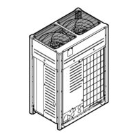
Double Fan Units381
-
Safety Devices382
-
Service Tools387
-
Field Settings388
-
To Use Mode 1388
-
To Use Mode 2389
Advertisement
Advertisement