Sign In
Upload
Manuals
Brands
Daikin Manuals
Chiller
EWFT-B-C
Daikin EWFT-B-C Manuals
Manuals and User Guides for Daikin EWFT-B-C. We have
1
Daikin EWFT-B-C manual available for free PDF download: Installation, Operation And Maintenance Manual
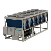
Daikin EWFT-B-C Installation, Operation And Maintenance Manual (51 pages)
Air Cooled Chiller with Scroll Compressors
Brand:
Daikin
| Category:
Chiller
| Size: 3 MB
Table of Contents
Table of Contents
2
Fig. 1- Refrigerant Circuit Diagram (P&ID) Standard Single Circuit Unit
4
Fig. 2 - Refrigerant Circuit Diagram (P&ID) Standard Dual Circuit Unit
5
Fig. 3-Hydronic Freecooling System (P&ID)
7
Introduction
9
Precautions against Residual Risks
9
General Description
10
Information about the Refrigerant
10
Usage
10
Installation Information
10
Receiving the Unit
13
Operating Limits
14
Storage
14
Operation Limits
14
Fig. 4- EWAT-B-C Silver Operational Limits
14
Fig. 5- EWAT-B-C Gold Operational Limits
15
Fig. 6- EWFT-B-C Silver Operational Limits
16
Fig. 7- EWFT-B-C Gold Operational Limits
17
Mechanical Installation
19
Safety
19
Safety Devices
19
Handling and Lifting
19
Safety Hook
21
Fig. 8- Lifting Instructions
21
Lifting Shackles
22
Fig. 9- Lifting Hook Characteristics
22
Fig. 10- Lifting Hook Installation
22
Fig. 11- Lifting Shackles Characteristics
22
Positioning and Assembly
23
Fig. 12- Lifting Shackles Installation
23
Minimum Space Requirements
24
Fig. 13- Unit Levelling
24
Fig. 14- Minimum Space Requirements
25
Fig. 15- Multiple Chiller Installation
26
Installation of Hydronic Free-Cooling Piping Shipped Loose
27
Pipe Installation Details and Instructions
27
Fig. 16- Piping Outside the Footprint of Free-Cooling Units
27
Fig. 17- Details of the Piping Installation
27
Noise and Sound Protection
28
Installation of Anti-Vibration Damperst
28
Fig. 18- Mounting Anti-Vibration Elements (Supplied as Optional)
28
Fig. 19- Detail of Anti-Vibration Damper Fixing Screw
28
Water Circuit for the Connection of the Unit
29
Water Piping
29
Fig. 20- Detail of the Anti-Vibration Damper Installation
29
Fig. 21- Final Position of Anti-Vibration Damper
29
Installing the Flow Switch
30
Fig. 22- Hydraulic Diagram (Opt. 78-79-80-81/134-135-136-137)
30
Heat Recovery
31
Water Treatment
31
Fig. 23- Water Piping Connection for Heat Recovery Exchangers (Maximum Pressure 20 Bar)
31
Hydronic Freecooling System
32
Introduction
32
Op. 231 - Free Cooling Glycol Free
32
Fig. 24- Closed Loop Hydronic Free Cooling P&ID (Opt. 231)
33
Coolant Quality Requirements
34
First Operations at Unit Commissioning Start
35
Free Cooling Purge Valve Related
35
Operations in Case of Failure
35
Operating Stability and Minimum Water Content in the System
35
Anti-Freeze Protection for Evaporator and Recovery Exchangers
36
Electrical Installation
37
General Specifications
37
Electrical Supply
37
Electric Connections
37
Cable Requirements
38
Phase Unbalance
38
Electrical Panel Label Description
39
Fig. 25- Description of Labels Applied on the Electrical Panel Small
39
Fig. 26- Description of Labels Applied on the Electrical Panel Medium
39
Operator's Reponsibilities
40
Maintenance
41
Pressure / Temperature Table
42
Routine Maintenance
42
Microchannel Coils Maintenance
42
Electrical Maintenance
43
Service and Limited Warranty
43
Checks for the First Start-Up
46
Important Information on the Refrigerant Used
47
Factory and Field Charged Units Instructions
47
10 Periodic Checks and Commissioning of Pressure Equipment
48
11 Dismission and Disposal
49
12 Duration
50
Advertisement
Advertisement
Related Products
Daikin EWFH TZ D Series
Daikin EWFD TZ D Series
Daikin EWFS TZ D Series
Daikin EWAQ100DAYN
Daikin EWYQ050BAW
Daikin EWLD360J-SS
Daikin EWWH430DZXSA2
Daikin EWAQ011ACW1
Daikin EWWD VZ Series
Daikin EWWH110J-SS
Daikin Categories
Air Conditioner
Heat Pump
Remote Control
Chiller
Air Handlers
More Daikin Manuals
Login
Sign In
OR
Sign in with Facebook
Sign in with Google
Upload manual
Upload from disk
Upload from URL