Sign In
Upload
Manuals
Brands
Daikin Manuals
Air Conditioner
EBLA04E V Series
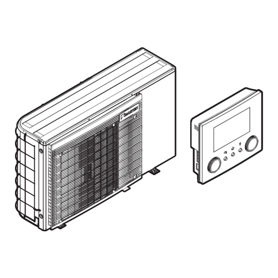
Daikin EBLA04E V Series Manuals
Manuals and User Guides for Daikin EBLA04E V Series. We have
1
Daikin EBLA04E V Series manual available for free PDF download: Service Manual
Daikin EBLA04E V Series Service Manual (324 pages)
Brand:
Daikin
| Category:
Air Conditioner
| Size: 58.61 MB
Table of Contents
Table of Contents
4
Safety Precautions
8
Meaning of Warnings and Symbols
8
Dangers
9
Warnings
9
Cautions
15
Notices
15
General Operation
16
Troubleshooting
18
To Display the Help Text in Case of a Malfunction
18
To Check the Malfunction History
18
Error Based Troubleshooting
19
01 - Water Flow Problem
19
04 - Water Flow Problem During Domestic Hot Water Production
20
05 - Water Flow Problem During Heating/Sampling
21
06 - Water Flow During Cooling/Defrost
22
07 - Water Flow Problem. Pump De-Blocking Active
23
08 - Pump Abnormality During Normal Operation (Pump Feedback)
23
Inlet Water Thermistor Abnormality
24
Outlet Water Thermistor Abnormality
24
Mixed Water Thermistor Abnormality
24
Outlet Water Temperature Thermistor Abnormality
25
Heat Exchanger Frozen
25
Heat Exchanger Frozen
26
Heat Exchanger Frozen
27
Heat Exchanger Freeze-Up Protection Activated During Cooling (Error)
27
Heat Exchanger Freeze-Up Protection Activated During Cooling (Warning)
28
00 - Abnormal Increase Outlet Water Temperature (Domestic Hot Water)
29
00 - Abnormal Increase Outlet Water Temperature
30
01 - Overheating Mixed Water Circuit
31
02 - Overheating Mixed Water Circuit (Thermostat)
31
03 - Overheating Water Circuit (Thermostat)
32
A1-00 - Zero Cross Detection Problem
32
A5-00 - Outdoor Unit: High Pressure Peak Cut / Freeze Protection Problem
33
Backup Heater Overheated
34
Booster Heater Overheated
35
Tank Disinfection Function Not Completed Correctly
35
Too Long Domestic Hot Water Heat-Up Time Required
36
C0-00 - Flow Sensor Malfunction
37
C0-01 - Flow Switch Malfunction
37
C0-02 - Flow Switch Malfunction
38
C4-00 - Heat Exchanger Temperature Sensor Problem
39
C5-00 - Heat Exchanger Thermistor Abnormality
39
Room Temperature Sensor Problem
40
E1-00 - Outdoor Unit: PCB Defect
40
E2-00 - Leakage Current Detection Error
41
E3-00 - Outdoor Unit: Actuation of High Pressure Switch
42
E3-24 - High Pressure Switch Abnormality
43
E4-00 - Abnormal Suction Pressure
44
E5-00 - Outdoor Unit: Overheat of Inverter Compressor Motor
45
E6-00 - Outdoor Unit: Compressor Startup Defect
46
E7-00 - Outdoor Unit: Malfunction of Outdoor Unit Fan Motor
47
E8-00 - Outdoor Unit: Power Input Overvoltage
47
E9-00 - Malfunction of Electronic Expansion Valve
48
Outdoor Unit: Cool/Heat Switchover Problem
49
Abnormal Increase Tank Temperature
50
Tank Preheating
50
F3-00 - Outdoor Unit: Malfunction of Discharge Pipe Temperature
51
F6-00 - Outdoor Unit: Abnormal High Pressure in Cooling
52
Outdoor Unit: Abnormal High Pressure, Actuation of High Pressure Switch
52
H0-00 - Outdoor Unit: Voltage/Current Sensor Problem
53
H1-00 - External Temperature Sensor Problem
54
H3-00 - Outdoor Unit: Malfunction of High Pressure Switch
55
H5-00 - Malfunction of Compressor Overload Protection
55
H6-00 - Outdoor Unit: Malfunction of Position Detection Sensor
56
H8-00 - Outdoor Unit: Malfunction of Compressor Input System
57
H9-00 - Outdoor Unit: Malfunction of Outdoor Air Thermistor
58
Tank Temperature Sensor Problem
58
Water Pressure Sensor Abnormality
58
J3-00 - Outdoor Unit: Malfunction of Discharge Pipe Thermistor
59
J6-00 - Outdoor Unit: Malfunction of Heat Exchanger Thermistor
59
J8-00 - Malfunction of Refrigerant Liquid Thermistor
60
Malfunction of High Pressure Sensor
60
Refrigerant Pressure Sensor Abnormality
61
L1-00 - Outdoor Unit: Main PCB Abnormality
61
L3-00 - Outdoor Unit: Electrical Box Temperature Rise Problem
62
L4-00 - Outdoor Unit: Malfunction of Inverter Radiating Fin Temperature Rise
63
L5-00 - Outdoor Unit: Inverter Instantaneous Overcurrent
63
L8-00 - Malfunction Triggered by a Thermal Protection in the Main PCB
65
L9-00 - Prevention of Compressor Lock
65
Malfunction in Communication System of Outdoor Unit
66
P1-00 - Open Phase Power Supply Imbalance
67
P3-00 - Abnormal Direct Current
67
P4-00 - Outdoor Unit: Malfunction of Radiating Fin Temperature Sensor
67
Capacity Setting Mismatch
68
U0-00 - Outdoor Unit: Shortage of Refrigerant
68
U1-00 - Malfunction by Reverse Phase/Open Phase
69
U2-00 - Outdoor Unit: Defect of Power Supply Voltage
70
U3-00 - under Floor Heating Screed Dry out Function Not Completed Correctly
70
U4-00 - Indoor/Outdoor Unit Communication Problem
71
U5-00 - User Interface Communication Problem
72
U7-00 - Outdoor Unit: Transmission Malfunction between Main Microcomputer - Inverter Microcomputer
73
U8-02 - Connection with Room Thermostat Lost
73
U8-03 - no Connection with Room Thermostat
74
U8-04 - Unknown USB Device
75
U8-05 - File Malfunction
75
U8-06 - Bizone Kit Canopen Communication Error
76
U8-07 - P1/P2 Communication Error
76
U8-09 - User Interface Software Version / Indoor Unit Compatibility Error
77
U8-11 - Connection with Wireless Gateway Lost
77
Indoor Unit, Outdoor Unit Mismatching Problem
78
Tank Type Problem
78
Reversed Piping or Bad Communication Wiring Detection
79
Symptom Based Troubleshooting
80
Symptom: Incorrect Energy Metering Read-Out
80
Water Pump Related
80
Tap Water Related
82
Symptom: User Interface Is Failure or Frozen Screen
83
Symptom: Leak
83
Symptom: Water Flow or Volume too Low
84
Compressor Related
84
Symptom: Abnormal Presence of Ice
87
Symptom: Domestic Hot Water Capacity Shortage
88
Symptom: General Capacity Shortage
89
Symptom: Space Heating (Cooling) Capacity Shortage
92
Symptom: Inaccurate Temperature Control
93
Symptom: Power Consumption too High
94
Symptom: System Does Not Start or Operate
96
Symptom: the Pump Is Blocked
98
Components
99
3-Way Valve
99
Checking Procedures
99
Repair Procedures
102
4-Way Valve
108
Checking Procedures
108
Repair Procedures
113
Backup Heater
116
Built-In Backup Heater
116
Backup Heater Kit
125
Backup Heater Thermal Protector
134
Built-In Backup Heater
134
Backup Heater Kit
137
Booster Heater
142
Checking Procedures
142
Repair Procedures
146
Booster Heater Thermal Protector
147
Checking Procedures
147
Repair Procedures
147
Compressor
148
Checking Procedures
148
Repair Procedures
153
Compressor Thermal Protector
158
Checking Procedures
158
Repair Procedures
160
Expansion Valve
162
Checking Procedures
162
Repair Procedures
166
Flow Switch
169
Checking Procedures
169
Repair Procedures
170
High Pressure Switch
171
Checking Procedures
171
Repair Procedures
173
Hydro PCB
175
Checking Procedures
175
Repair Procedures
178
LAN Adapter PCB
181
Checking Procedures
181
Repair Procedures
183
Main PCB
184
Checking Procedures
184
Repair Procedures
193
Outdoor Unit Fan Motor
197
Checking Procedures
197
Repair Procedures
199
Plate Work
202
To Remove the Discharge Grille
202
To Open the Outdoor Unit
202
To Remove the Top Plate
203
To Remove the Front Plate
203
To Rotate the Switch Box
204
To Remove the Compressor Sound Insulation
205
To Remove the Drip Proof Cover
205
To Remove the Switch Box
206
To Install the Switch Box
208
To Close the Outdoor Unit
209
Reactor
210
Checking Procedures
210
Repair Procedures
212
Refrigerant Pressure Sensor
212
Checking Procedures
212
Repair Procedures
215
Thermistors
217
Refrigerant Side Thermistors
217
Water Side Thermistors
223
Other Thermistors
229
User Interface
234
Checking Procedures
234
Repair Procedures
236
Water Flow Sensor
237
Checking Procedures
237
Repair Procedures
238
Water Pressure Sensor
241
Checking Procedures
241
Repair Procedures
243
Water Pump
245
Checking Procedures
245
Repair Procedures
248
Third Party Components
254
Electrical Circuit
254
Checking Procedures
254
Repair Procedures
256
Refrigerant Circuit
256
Checking Procedures
256
Repair Procedures
261
Water Circuit
265
Checking Procedures
265
Repair Procedures
269
Manufacturer Components
273
Checking Procedures
273
Repair Procedures
273
External Factors
274
Checking Procedures
274
Maintenance
275
To Clean the Outdoor Unit Heat Exchanger
275
To Clean the Integrated Filter of the Shut-Off Valve
275
To Check the Pipe Heaters
276
Technical Data
280
Detailed Information Setting Mode
280
Detailed Information Setting Mode: Outdoor Unit
280
Detailed Information Setting Mode: Remote Controller
280
Wiring Diagram
281
Wiring Diagram: Outdoor Unit
281
Piping Diagram
297
Piping Diagram: Outdoor Unit
297
Component Overview
299
Component Overview: Single Phase with Backup Heater
299
Component Overview: Single Phase Without Backup Heater
301
Component Overview: Backup Heater Kit
303
Field Information Report
304
Service Tools
307
Field Settings
308
Advertisement
Advertisement
Related Products
Daikin EBLA04E2V3
Daikin EBLA04E23V3
Daikin EBLA09DAW1
Daikin EBLA09DA3W1
Daikin EBLA06E2V3
Daikin EBLA08E23V3
Daikin EBLA09D V3 Series
Daikin EBLA09D 3W1 Series
Daikin EBLA08E V Series
Daikin EBLA06E V Series
Daikin Categories
Air Conditioner
Heat Pump
Remote Control
Chiller
Controller
More Daikin Manuals
Login
Sign In
OR
Sign in with Facebook
Sign in with Google
Upload manual
Upload from disk
Upload from URL