Daikin Altherma ERGA06E V3H Series Manuals
Manuals and User Guides for Daikin Altherma ERGA06E V3H Series. We have 2 Daikin Altherma ERGA06E V3H Series manuals available for free PDF download: Installer's Reference Manual
Daikin Altherma ERGA06E V3H Series Installer's Reference Manual (296 pages)
Table of Contents
-
-
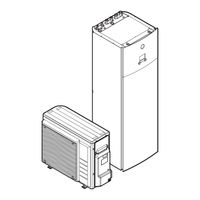
Outdoor Unit22
-
Indoor Unit24
-
-
-
-
-
-
10 Configuration
138-
Possible Screens143
-
Home Screen144
-
Main Menu Screen146
-
Menu Screen147
-
Setpoint Screen147
-
Settings Menu163
-
Malfunctioning163
-
Room164
-
Main Zone168
-
Additional Zone179
-
Tank192
-
User Settings200
-
Information205
-
Commissioning226
-
User Profile226
-
Operation227
-
Wlan227
-
-
11 Commissioning
232 -
-
-
15 Disposal
263-
To Pump down263
-
17 Glossary
282
Advertisement

Daikin Altherma ERGA06E V3H Series Installer's Reference Manual (288 pages)
Table of Contents
-
General10
-
Water13
-
Electrical13
-
Outdoor Unit22
-
Indoor Unit24
-
Single Room33
-
Configuration134
-
Possible Screens139
-
Home Screen140
-
Main Menu Screen142
-
Menu Screen143
-
Setpoint Screen143
-
2-Points Curve155
-
Settings Menu159
-
Malfunctioning159
-
Room160
-
Main Zone164
-
Additional Zone175
-
Tank188
-
User Settings196
-
Information201
-
Commissioning222
-
User Profile223
-
Operation223
-
Wlan223
-
Commissioning228
-
Troubleshooting246
-
Disposal257
-
To Pump down257
-
Technical Data259
-
Glossary274
Advertisement