Sign In
Upload
Manuals
Brands
Curtiss-Wright Manuals
Desktop
C312-07
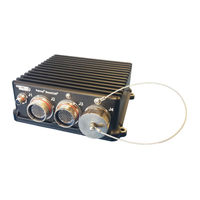
Curtiss-Wright C312-07 Manuals
Manuals and User Guides for Curtiss-Wright C312-07. We have
1
Curtiss-Wright C312-07 manual available for free PDF download: User Manual
Curtiss-Wright C312-07 User Manual (59 pages)
Brand:
Curtiss-Wright
| Category:
Desktop
| Size: 2 MB
Table of Contents
Table of Contents
3
Chapter 1 - Introduction
8
About this Document
8
Manual Organization
8
Definitions
8
Description of Safety Symbols
8
Functional Description
10
Features
10
Applications
11
Configurations
11
Base System
11
Table 1 Duracor 312 Standard Configurations
11
Base System with Removable Storage Bay Option
12
System Block Diagram
12
Figure 1: System Block Diagram
12
Shared Resources and Connectors Location
13
Table 2: Chip List
13
Figure 2: SATA Expansion
14
Chapter 2 - Quick Start Guide
15
Recommended Equipment
15
Breakout Cable Set
15
Power-On Sequence
15
Chapter 3 - Connector Descriptions
16
Connector Identification
16
Table 3: Duracor 312 Connector Identification Table
16
Connector Pinouts
17
J1 Power Connector
17
Figure 3: Duracor 312 J1 Front Pinout
17
Table 4: J1 Connector Information
17
Table 5: J1 Pinout
17
J2 I/O Connector
18
Figure 4: Duracor 312 J2 Front Pinout
18
Table 6: J2 Connector Information
18
Table 7: J2 Pinout
19
J3 I/O Connector
20
Figure 5: Duracor 312 J3 Front Pinout
20
Table 8: J3 Connector Information
21
Table 9: J3 Pinout
21
J4 Configurable I/O Connector
22
Optional Internal IO Expansion Connectors
23
Figure 6: Duracor 312 J4 Front Pinout
23
Table 10: J4 Connector Information
23
Chapter 4 - Operational Description
25
Pcie
25
Mini-Pcie Expansion
25
Figure 7: Pcie Lane Mapping
25
Installing Mini-Pcie Cards into the Duracor 311 Mission Computer
26
Integrating Mini-Pcie Cards
26
Figure 8: Mini-Pcie Cards from Various Manufactureres
26
Storage Options
27
Non-Volatile Memory Express (Nvme)
27
M.2 Socket
27
Sata
27
Figure 9: Card Slot Identification, Mini-Pcie Slot 1 (Top Card, Left Image), Mini-Pcie Slot 2
27
M.2 Socket
28
Removable SATA
28
Installing the Removable Device
28
Removing the Removable Device
28
Accessories
28
Flash Storage
28
Figure 10: SSD Removable Tray
28
Usb
29
Usb 2.0
29
Usb0
29
Usb1
29
Usb2
29
Usb 3.0
29
Ethernet
29
Gbe1
29
Gbe2
30
Serial
30
BIT Port
30
Console
30
Multiprotocol Ports
30
Can
32
Gpio
32
Audio
33
Hdmi
33
The Default System Configuration Exposes a Single HDMI Interface through J3. this Port Can be Connected to any HDMI Capable Display
33
Zeroization
34
Built-In-Test (BIT)
34
Flashing os Image
34
Chapter 5 Specifications
35
Technical Specifications
35
Multi-Core Arm/Pascal GPU
35
Standard I/O Interfaces
35
I/O Expansion
36
Operating System
36
Storage
36
Mechanical Specifications
36
Physical
36
Dimensions
37
Mounting the System
37
Power
37
Environmental Specifications
38
Temperature
38
Shock/Vibration
38
EMI/EMC Compliance
38
Operating Conditions
38
Other Specifications
39
Reliability
39
Export Jurisdiction
39
Regulatory Compliance
39
Chapter 6 Troubleshooting
40
Product Identification
40
Technical Assistance
40
Returning for Service
40
Warranty
40
Chapter 7 Contact Info
41
NVIDIA Jetson Tx2I Configurations
42
NVIDIA Documentation
42
Figure 11: Pcie/Usb 3.0 Lane Mapping Configurations
42
BIT Port
43
High Temperature Operation
44
Linux Software Development
48
Instructions for Setting up a Project Directory
49
Description of Source Files
49
Overview
50
Detailed Instructions
50
How to Deploy an Image to C312
54
Additional Notes
54
LAN 7800 Notes
56
Glossary
58
Advertisement
Advertisement
Related Products
Curtiss-Wright C312-00R
Curtiss-Wright C312-00
Curtiss-Wright C312-01
Curtiss-Wright C312-02
Curtiss-Wright C312-03
Curtiss-Wright C312-04
Curtiss-Wright C312-05
Curtiss-Wright C312-06
Curtiss-Wright C311-01
Curtiss-Wright C311-53
Curtiss-Wright Categories
Computer Hardware
PCI Card
Controller
Switch
Measuring Instruments
More Curtiss-Wright Manuals
Login
Sign In
OR
Sign in with Facebook
Sign in with Google
Upload manual
Upload from disk
Upload from URL