Sign In
Upload
Manuals
Brands
CTI Manuals
Control Unit
2550
CTI 2550 Manuals
Manuals and User Guides for CTI 2550. We have
1
CTI 2550 manual available for free PDF download: Installation And Operation Manual
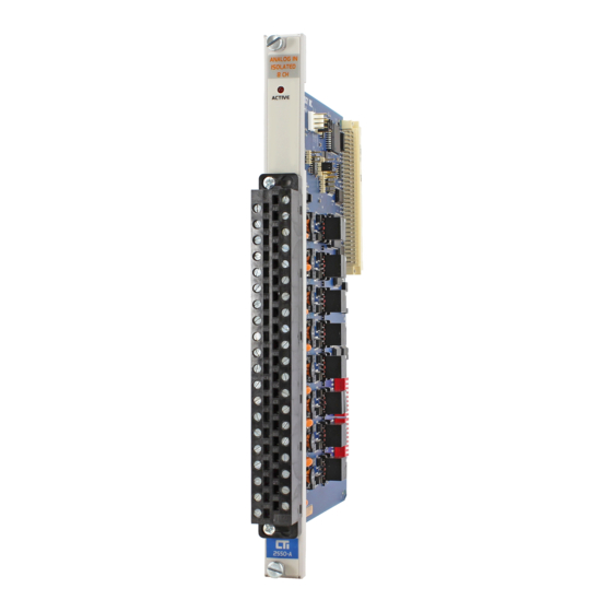
CTI 2550 Installation And Operation Manual (47 pages)
EIGHT CHANNEL ISOLATED ANALOG INPUT MODULE
Brand:
CTI
| Category:
Control Unit
| Size: 3 MB
Table of Contents
Preface
6
Usage Conventions
8
Table of Contents
10
Table of Figures
12
Chapter 1. Description
14
Front Panel Description
14
Active LED
14
Figure 2 2550 Front Panel
14
Input Connector for Channels 1-4
15
Input Connector for Channels 5-8
15
Asynchronous Operation
15
Unipolar or Bipolar Mode
15
Voltage or Current Mode
15
Digital Word Map
15
Analog to Digital Conversion
16
Unipolar Mode Conversion
16
Figure 3 Word Input to the PLC from the Module (Unipolar)
16
Figure 4 Word Input to the PLC from the Module (Bipolar)
16
Figure 5 Maximum Non-Overrange Word Value (Unipolar)
17
Figure 6 Minimum Non-Underrange Word Value (Unipolar)
17
Bipolar Mode Conversion
18
Figure 7 Maximum Non-Overrange Word Value (Bipolar)
18
Example Conversion
19
Figure 8 Minimum Non-Underrange Word Value (Bipolar)
19
Figure 9 Example of Change in Input Level
19
Effect of Out-Of-Range Input Signals
20
Figure 10 Voltage Input Limits (Unipolar)
20
Figure 11 Voltage Input Limits (Bipolar)
20
Figure 12 Overrange Word Value (Unipolar)
21
Figure 13 Underrange Word Value (Unipolar)
21
Figure 14 Overrange Word Value (Bipolar)
21
Using the Module with 20% Offset
23
Resolution
23
Figure 15 Underrange Word Value (Bipolar)
23
Figure 16 Input Resolution
24
Chapter 2. Installation
26
Planning the Installation
26
Calculating the I/O Base Power Budget
26
Input Signal Wiring
26
Unpacking the Module
27
Configuring the Module
28
Selecting Voltage or Current Input Mode
28
Selecting Voltage Range
29
Selecting Unipolar or Bipolar Input Mode
29
Figure 17 Factory Configuration Jumper Settings
29
Selecting Digital Filtering
30
Figure 18 Configuration Jumper Locations
30
Inserting the Module into the I/O Base
31
Wiring the Input Connectors
31
Figure 19 Screw Terminal Plug Wiring
32
Connecting Current Input Wiring
33
Connecting Voltage Input Wiring
33
Inserting the Screw Terminal Plug
33
Figure 20 Input Connector Wiring
33
Checking Module Operation
34
Figure 21 Example I/O Configuration Chart
34
Figure 22 Troubleshooting Matrix
36
Chapter 3. Troubleshooting
36
Specifications
38
Jumper Settings Log Sheet
40
Figure 23 Jumper Settings Log
40
User Notes
42
Limited Product Warranty
44
Repair Policy
46
Advertisement
Advertisement
Related Products
CTI 2572-A
CTI 2552
CTI 2550-A
CTI 2500-VP15
CTI 2500C-2572-B
CTI 2500 Series
CTI 2500-C100
CTI 2500C-C300
CTI 2500P-J Series
CTI 2500P-J750
CTI Categories
Controller
Accessories
Control Unit
Gas Detectors
Control Panel
More CTI Manuals
Login
Sign In
OR
Sign in with Facebook
Sign in with Google
Upload manual
Upload from disk
Upload from URL