
Related Manuals for CTI 2550

Summary of Contents for CTI 2550
- Page 1 (217) 352-9330 | Click HERE Find the Control Technology 2550 at our website:...
- Page 2 CTI 2550 EIGHT CHANNEL ISOLATED ANALOG INPUT MODULE INSTALLATION AND OPERATION GUIDE Version 2.0 CTI Part #062-00102 2452IOG 092205 Artisan Technology Group - Quality Instrumentation ... Guaranteed | (888) 88-SOURCE | www.artisantg.com...
- Page 3 CT I 2550 Installation and O peration G uide Artisan Technology Group - Quality Instrumentation ... Guaranteed | (888) 88-SOURCE | www.artisantg.com...
- Page 4 Every effort has been made to ensure the accuracy of this document; however, errors do occasionally occur. CTI provides this document on an "as is" basis and assumes no responsibility for direct or consequential damages resulting from the use of this document. This document is provided without express or implied warranty of any kind, including but not limited to the warranties of merchantablility or fitness for a particular purpose.
- Page 5 CT I 2550 Installation and O peration G uide Artisan Technology Group - Quality Instrumentation ... Guaranteed | (888) 88-SOURCE | www.artisantg.com...
-
Page 6: Preface
PREFACE This Installation and Operation Guide provides installation and operation instructions for the CTI 2550 Eight Channel Isolated Analog Input Module for SIMATIC® 505 programmable controllers. We assume you are familiar with the operation of the SIMATIC® 505 programmable controllers. - Page 7 CT I 2550 Installation and O peration G uide Artisan Technology Group - Quality Instrumentation ... Guaranteed | (888) 88-SOURCE | www.artisantg.com...
-
Page 8: Usage Conventions
Cautions alert the user to procedures which could damage equipment. WARNING: Warnings alert the user to procedures which could damage equipment and endanger the user. CT I 2550 Installation and O peration G uide Artisan Technology Group - Quality Instrumentation ... Guaranteed | (888) 88-SOURCE | www.artisantg.com... - Page 9 CT I 2550 Installation and O peration G uide Artisan Technology Group - Quality Instrumentation ... Guaranteed | (888) 88-SOURCE | www.artisantg.com...
-
Page 10: Table Of Contents
CHAPTER 3. TROUBLESHOOTING ..........19 CT I 2550 Installation and O peration G uide... - Page 11 REPAIR POLICY ............29 CT I 2550 Installation and O peration G uide...
-
Page 12: Table Of Figures
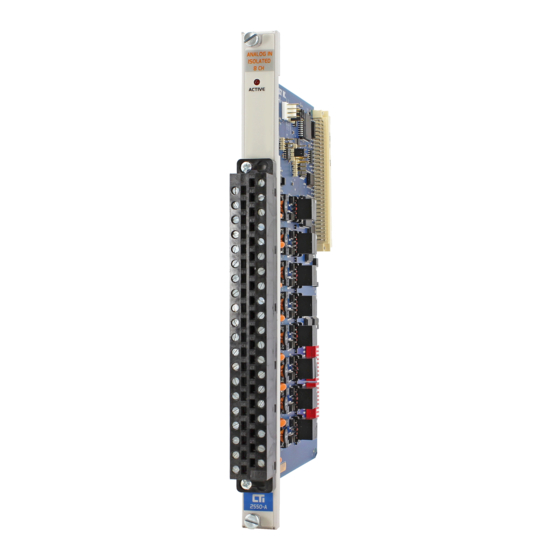
TABLE OF FIGURES Figure 1 The Model 2550 8-Channel Isolated Analog Input Module ..... . v Figure 2 2550 Front Panel ............1 Figure 3 Word Input to the PLC from the Module (Unipolar) . - Page 13 CT I 2550 Installation and O peration G uide Artisan Technology Group - Quality Instrumentation ... Guaranteed | (888) 88-SOURCE | www.artisantg.com...
-
Page 14: Chapter 1. Description
The Eight Channel Analog Input Module is a member of Control Technology's family of I/O modules compatible with the SIMATIC® 505 programmable controllers. The Model 2550 is designed to translate an analog input signal into an equivalent digital word which is then sent to the programmable controller (PLC). -
Page 15: Input Connector For Channels 1-4
“overrange”, and the remaining bits are not used and are set to zero. CT I 2550 Installation and O peration G uide Artisan Technology Group - Quality Instrumentation ... Guaranteed | (888) 88-SOURCE | www.artisantg.com... -
Page 16: Analog To Digital Conversion
The following equations may be used to calculate the digital word which will result from a particular voltage or current input in the Unipolar Input Mode: CT I 2550 Installation and O peration G uide Artisan Technology Group - Quality Instrumentation ... Guaranteed | (888) 88-SOURCE | www.artisantg.com... -
Page 17: Figure 5 Maximum Non-Overrange Word Value (Unipolar)
The following figures show the bit conditions for the maximum and minimum non-overrange values in Figure 5 Maximum Non-Overrange Word Value (Unipolar) Figure 6 Minimum Non-Underrange Word Value (Unipolar) unipolar mode: CT I 2550 Installation and O peration G uide Artisan Technology Group - Quality Instrumentation ... Guaranteed | (888) 88-SOURCE | www.artisantg.com... -
Page 18: Bipolar Mode Conversion
The following figures show the bit conditions for the maximum and minimum non-overrange values in Figure 7 Maximum Non-Overrange Word Value (Bipolar) bipolar mode: CT I 2550 Installation and O peration G uide Artisan Technology Group - Quality Instrumentation ... Guaranteed | (888) 88-SOURCE | www.artisantg.com... -
Page 19: Example Conversion
Bipolar Modes, refer to the formulas given in Sections 1.6.1 and 1.6.2 to determine the digital Figure 9 Example of Change in Input Level word which results from a particular input.) CT I 2550 Installation and O peration G uide Artisan Technology Group - Quality Instrumentation ... Guaranteed | (888) 88-SOURCE | www.artisantg.com... -
Page 20: Effect Of Out-Of-Range Input Signals
Figures 7 and 8 for maximum and minimum bipolar word values. See Figures 14 and 15 for overrange and underrange bipolar word values. CT I 2550 Installation and O peration G uide Artisan Technology Group - Quality Instrumentation ... Guaranteed | (888) 88-SOURCE | www.artisantg.com... -
Page 21: Figure 12 Overrange Word Value (Unipolar)
Figure 14 Overrange Word Value (Bipolar) Figures 14 and 15 show the binary values of overrange and underrange conditions for Bipolar mode. CT I 2550 Installation and O peration G uide Artisan Technology Group - Quality Instrumentation ... Guaranteed | (888) 88-SOURCE | www.artisantg.com... - Page 22 CT I 2550 Installation and O peration G uide Artisan Technology Group - Quality Instrumentation ... Guaranteed | (888) 88-SOURCE | www.artisantg.com...
-
Page 23: Using The Module With 20% Offset
10 counts out of 32000 as a result of the multiplication and division of the incoming data word. CT I 2550 Installation and O peration G uide Artisan Technology Group - Quality Instrumentation ... Guaranteed | (888) 88-SOURCE | www.artisantg.com... -
Page 24: Figure 16 Input Resolution
The chart below shows the corresponding input resolution per step for each of the input configuration Figure 16 Input Resolution modes: CT I 2550 Installation and O peration G uide Artisan Technology Group - Quality Instrumentation ... Guaranteed | (888) 88-SOURCE | www.artisantg.com... - Page 25 CT I 2550 Installation and O peration G uide Artisan Technology Group - Quality Instrumentation ... Guaranteed | (888) 88-SOURCE | www.artisantg.com...
-
Page 26: Chapter 2. Installation
2.1.1 Calculating the I/O Base Power Budget The Model 2550 requires 2.5 watts of +5 V power from the I/O base. Use this value to verify that the base power supply capacity is not exceeded. 2.1.2 Input Signal Wiring Input signal wiring must be shielded twisted-pair cable. -
Page 27: Unpacking The Module
CAUTION: HANDLING STATIC SENSITIVE DEVICES The components on the Model 2550 module printed circuit card can be damaged by static electricity discharge. To prevent this damage, the module is shipped in a special anti-static bag. Static control precautions should be followed when removing the module from the bag, when opening the module, and when handling the printed circuit card during configuration. -
Page 28: Configuring The Module
2.3 Configuring the Module The Model 2550 must be configured for voltage or current inputs, voltage range, unipolar/bipolar mode, and digital filtering/no filtering mode before wiring the input connectors and inserting the module into the I/O base. As shipped, all input channels are configured for current inputs, 5V range (see Note below), unipolar mode, and digital filtering enabled (see Figure 17). -
Page 29: Selecting Voltage Range
BIP for bipolar operation. Note that the Unipolar/Bipolar Jumper settings affect all 8 input channels. CT I 2550 Installation and O peration G uide Artisan Technology Group - Quality Instrumentation ... Guaranteed | (888) 88-SOURCE | www.artisantg.com... -
Page 30: Selecting Digital Filtering
2.3.4 Selecting Digital Filtering Locate the Digital Filtering/No Filtering Jumper JP6 (see Figure 18). To enable digital filtering, set the jumper in the FIL position. Since many analog input signals contain noise, CTI recommends using digital filtering unless maximum response time is required. -
Page 31: Inserting The Module Into The I/O Base
To assign an input to a specific channel, locate the appropriate channel position on the screw terminal plug as shown in the following figure: CT I 2550 Installation and O peration G uide Artisan Technology Group - Quality Instrumentation ... Guaranteed | (888) 88-SOURCE | www.artisantg.com... -
Page 32: Figure 19 Screw Terminal Plug Wiring
Figure 19 Screw Terminal Plug Wiring CT I 2550 Installation and O peration G uide Artisan Technology Group - Quality Instrumentation ... Guaranteed | (888) 88-SOURCE | www.artisantg.com... -
Page 33: Connecting Voltage Input Wiring
Figure 20 Input Connector Wiring locking tabs snap over the connector lip to secure the screw terminal plug to the header. CT I 2550 Installation and O peration G uide Artisan Technology Group - Quality Instrumentation ... Guaranteed | (888) 88-SOURCE | www.artisantg.com... -
Page 34: Checking Module Operation
An example chart is shown in the following figure. In this example, the Model 2550 module is inserted in slot 1 in I/O base 1. Data for channel 1 appears in word location WX1, data for channel 2 appears in word location WX2, etc. For your particular module, look in the chart for the number corresponding to the slot occupied by the module. - Page 35 CT I 2550 Installation and O peration G uide Artisan Technology Group - Quality Instrumentation ... Guaranteed | (888) 88-SOURCE | www.artisantg.com...
-
Page 36: Chapter 3. Troubleshooting
The module fuse is not user serviceable. If this fuse is blown, the module has a serious component failure and should be returned to CTI for repair. supply) fails, the module will still be logged into the PLC even though it is not operating. In this case, “Display Failed I/O”... - Page 37 CT I 2550 Installation and O peration G uide Artisan Technology Group - Quality Instrumentation ... Guaranteed | (888) 88-SOURCE | www.artisantg.com...
-
Page 38: Specifications
Humidity, Relative: 5% to 95% (non-condensing) Shipping Weight: 1.5 lbs (0.68 Kg) Specifications subject to change without notice. CT I 2550 Installation and O peration G uide Artisan Technology Group - Quality Instrumentation ... Guaranteed | (888) 88-SOURCE | www.artisantg.com... - Page 39 CT I 2550 Installation and O peration G uide Artisan Technology Group - Quality Instrumentation ... Guaranteed | (888) 88-SOURCE | www.artisantg.com...
-
Page 40: Jumper Settings Log Sheet
Figure 23 Jumper Settings Log Record the configuration jumper settings on this log for future reference. Make additional copies if necessary. CT I 2550 Installation and O peration G uide Artisan Technology Group - Quality Instrumentation ... Guaranteed | (888) 88-SOURCE | www.artisantg.com... - Page 41 CT I 2550 Installation and O peration G uide Artisan Technology Group - Quality Instrumentation ... Guaranteed | (888) 88-SOURCE | www.artisantg.com...
-
Page 42: User Notes
USER NOTES CT I 2550 Installation and O peration G uide Artisan Technology Group - Quality Instrumentation ... Guaranteed | (888) 88-SOURCE | www.artisantg.com... - Page 43 CT I 2550 Installation and O peration G uide Artisan Technology Group - Quality Instrumentation ... Guaranteed | (888) 88-SOURCE | www.artisantg.com...
-
Page 44: Limited Product Warranty
Products become the property of CTI. Should any Product or part returned to CTI hereunder be found by CTI to be without defect, CTI will return such Product or part to the customer. This warranty does not include repair of damage to a part or the Product resulting from: failure to... - Page 45 CT I 2550 Installation and O peration G uide Artisan Technology Group - Quality Instrumentation ... Guaranteed | (888) 88-SOURCE | www.artisantg.com...
-
Page 46: Repair Policy
Authorization number (RMA) can be requested verbally or in writing from CTI main offices. Whether this equipment is in or out of warranty, a Purchase Order number provided to CTI when requesting the RMA number will aid in expediting the repair process. The RMA number that is issued and your Purchase Order number should be referenced on the returning equipment's shipping documentation.
Need help?
Do you have a question about the 2550 and is the answer not in the manual?
Questions and answers