Sign In
Upload
Manuals
Brands
Crowcon Manuals
Control Panel
Vortex
Crowcon Vortex Gas Control Panel Manuals
Manuals and User Guides for Crowcon Vortex Gas Control Panel. We have
2
Crowcon Vortex Gas Control Panel manuals available for free PDF download: Manual, Installation, Operation And Maintenance Manual
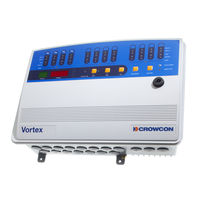
Crowcon Vortex Manual (92 pages)
12 Channel Gas and Fire Control Panel
Brand:
Crowcon
| Category:
Control Panel
| Size: 2 MB
Table of Contents
Table of Contents
3
1 Introduction
9
What this Manual Is for
9
What Is Vortex
9
Who Should Use this Manual
9
Table 1: Vortex Options
9
What this Manual Contains
10
Table 2: Which Sections of this Manual to Read
10
2 System Overview
11
General
11
System Description
11
System Modules and Options
11
Table 3: List of Vortex Modules
11
Input/Output Capability
12
Figure 1 : General Assembly of Vortex Modules
12
Digital Communications
13
Specification
13
Table 4: Vortex Specification
13
Approvals
14
3 Installation
15
General
15
Before Installation
15
Installation of a Pre-Configured Vortex System
15
Installation of an Un-Configured Vortex System
17
General
17
Figure 2: Vortex System in Standard Enclosure
17
Building a Vortex System
18
Building the System
18
Installing the System
19
Cabling
20
Circuit Breaker
21
Table 5: Cable Characteristics
21
Zero Adjustment and Calibration of Vortex
22
General
22
Zero Adjustment and Calibration Procedure
22
4 Technical Information: Vortex
24
General
24
Node Controller Module
25
Functions of the Node Controller Module
25
Figure 3: Node Controller Module
25
Node Controller Module Indicators, Switches and Connectors
26
Table 6: Node Controller Module Indicators, Switches and Connectors
26
Configuring the Node Controller Module
27
Table 7: System Configuration Properties
27
The Bus Rail and Electrical Connections
28
Figure 4: Bus Rail Assembly Details
28
Quad Channel Input Module
29
Functions of the Quad Channel Input Module
29
Figure 5: Quad Channel Input Module
29
Configuring the Quad Channel Input Module
30
Figure 6: Switches on Quad Channel Input Module
30
Table 8: Quad Channel Input Module Switch Settings
30
Table 9: Detector Channel Configurable Properties
31
Relay Output Module
33
Functions of the Relay Output Module
33
Figure 7: Relay Output Module
33
Table 10: Features of the Relay Output Module
33
Configuring the Relay Output Module
34
Table 11: Relay Output Module Switch Settings
34
Figure 8: Relay Ouput Module Selection Switch
35
Table 12: Relay Configurable Properties
35
Table 13: Relay Output Types
36
Configuring the Relay Logic
38
The Display Module
39
Functions of the Display Module
39
Figure 9: Back of Display Module
39
Table 14: Relay Logic Configurable Properties
39
Figure 10: Front of Display Module
40
Display Module Features
41
Table 15: Display Module Features
41
Power Monitoring Module
43
Functions of the Power Monitoring Module
43
Figure 11: Power Monitoring Module
43
Table 16: Features of the Power Monitoring Module
44
Removing the 5-Way Cable Assembly
45
Mounting the Power Monitoring Module on a DIN Rail
45
Backup Batteries
46
Figure 12: Alternative Mountings for the Power Monitoring Module
46
Power Failure
47
5 Technical Information: Field Devices
48
General
48
Gas Detectors
48
Gas Detector Location
48
Fire Detectors
49
Figure 13: Representation of a Fire Detection Circuit
49
Fire Detector Location
50
Connections for Audible/Visual Alarms
50
6 Operation
51
General
51
Monitoring with the Display Module
51
Alarm Conditions and Faults
52
Display Module
52
Internal Sounder and Relays
52
Fault Messages
52
Channel Faults
52
Table 17: List of Channel Faults
53
Power Status
54
Table 18: List of Power Status LED Codes
54
System Faults
55
Table 19: List of Node Controller Module LED Fault Codes
55
7 Maintenance
57
Detector Functional Testing
57
Inhibiting Input
57
Re-Calibration of Vortex
57
Channel Test Mode
59
Channel Test Mode Procedure
59
Table 20: Channel Test Display Sequences
60
Setting Alarm Levels
61
Lamp Test
61
Event Logging
62
Table 21: Data Recorded in the Event Log
62
Module Replacement
63
Mounting and Dismounting DIN Rail Modules
63
Changing the Batteries
64
Figure 14: Module on DIN Rail, and Method of Removal
64
Figure 15: Removing Batteries from Vortex Standard Enclosure
65
Appendix A: Glossary
66
Appendix B: Electrical Connections
68
Figure 17: Wiring Diagram for the Node Controller Module
70
Figure 18: Wiring Diagram for the Quad Channel Input Module
71
Figure 19: Wiring Diagram for the Relay Output Module
72
Appendix C: List of Spare Parts
73
Appendix D: Crowcon Detector Range
74
Appendix E: Vortex Configuration
76
Appendix F: Earthing
79
Introduction
79
Definitions
79
Questions
79
Figure 20 Decision Tree for Determining Earthing Requirements
81
Diagrams
82
Diagram 1
82
Diagram 2
83
Diagram 3
84
Diagram 4A
86
Diagram 4B
87
Diagram 5A
88
Diagram 5B
89
Wiring Standards
89
Warranty Statement
91
Advertisement
Crowcon Vortex Installation, Operation And Maintenance Manual (80 pages)
12 Channel Gas and Fire Control Panel
Brand:
Crowcon
| Category:
Control Panel
| Size: 2 MB
Table of Contents
Table of Contents
3
1 Introduction
7
What this Manual Is for
7
What Is Vortex
7
Who Should Use this Manual
7
Figure 2: Vortex System in Standard Enclosure
7
Table 1: Vortex Options
7
What this Manual Contains
8
Table 2: Which Sections of this Manual to Read
8
2 System Overview
9
General
9
System Description
9
System Modules and Options
9
Table 3: List of Vortex Modules
9
Input/Output Capability
10
Digital Communications
11
Specification
11
Table 4: Vortex Specification
11
Approvals
12
3 Installation
13
General
13
Before Installation
13
Installation of a Pre-Configured Vortex System
14
Installation of an Un-Configured Vortex System
15
General
15
Building a Vortex System
16
Building the System
16
Installing the System
17
Cabling
18
Table 5: Cable Characteristics
18
Circuit Breaker
19
Zero Adjustment and Calibration of Vortex
19
General
19
Zero Adjustment and Calibration Procedure
20
4 Technical Information: Vortex
21
General
21
Node Controller Module
21
Functions of the Node Controller Module
21
Node Controller Module Indicators, Switches and Connectors
22
Table 6: Node Controller Module Indicators, Switches and Connectors
22
Configuring the Node Controller Module
23
Table 7: System Configuration Properties
23
The Bus Rail and Electrical Connections
24
Quad Channel Input Module
25
Functions of the Quad Channel Input Module
25
Configuring the Quad Channel Input Module
26
Table 8: Quad Channel Input Module Switch Settings
26
Table 9: Detector Channel Configurable Properties
27
Relay Output Module
29
Functions of the Relay Output Module
29
Configuring the Relay Output Module
30
Table 10: Features of the Relay Output Module
30
Table 11: Relay Output Module Switch Settings
31
Figure 8: Relay Ouput M Odule Select Ion Swit Ch
31
Table 12: Relay Configurable Properties
32
Table 13: Relay Output Types
33
Configuring the Relay Logic
35
The Display Module
36
Functions of the Display Module
36
Table 14: Relay Logic Configurable Properties
36
Figure 10: Front of Display M Odule
37
Display Module Features
38
Table 15: Display Module Features
38
Power Monitoring Module
40
Functions of the Power Monitoring Module
40
Table 16: Features of the Power Monitoring Module
41
Removing the 5-Way Cable Assembly
42
Mounting the Power Monitoring Module on a DIN Rail
42
Backup Batteries
43
Power Failure
44
5 Technical Information: Field Devices
44
General
44
Gas Detectors
44
Gas Detector Location
44
Fire Detectors
45
Fire Detector Location
46
Connections for Audible/Visual Alarms
46
6 Operation
47
General
47
Monitoring with the Display Module
47
Alarm Conditions and Faults
48
Display Module
48
Internal Sounder and Relays
48
Fault Messages
49
Channel Faults
49
Table 17: List of Channel Faults
49
Power Status
50
System Faults
50
Table 18: List of Power Status LED Codes
50
Table 19: List of Node Controller Module LED Fault Codes
50
7 Maintenance
51
Detector Functional Testing
51
Inhibiting Input
51
Re-Calibration of Vortex
52
Channel Test Mode
53
Channel Test Mode Procedure
53
Table 20: Channel Test Display Sequences
54
Setting Alarm Levels
55
Lamp Test
55
Event Logging
56
Table 21: Data Recorded in the Event Log
56
Module Replacement
57
Mounting and Dismounting DIN Rail Modules
58
Changing the Batteries
58
Figure 15: Rem Oving Bat T Eries from Vortex St Andard Enclosure
59
Appendix A: Glossary
60
Appendix B: Electrical Connections
62
Figure 17: Wiring Diagram for T He Node Cont Roller M Odule
63
Figure 18: Wiring Diagram for T He Quad Channel Input M Odule
64
Figure 19: Wiring Diagram for T He Relay out Put M Odule
65
Appendix C: List of Spare Parts
66
Appendix D: Crowcon Detector Range
67
Appendix E: Vortex Configuration
69
Appendix F: Earthing
71
Introduction
71
Definitions
71
Questions
71
Figure 20 Decision Tree for Det Ermining Eart Hing Requirem Ent S
72
Diagrams
73
Diagram 1
73
Diagram 2
73
Diagram 3
74
Diagram 4A
76
Diagram 4B
76
Diagram 5A
77
Diagram 5B
77
Wiring Standards
78
Advertisement
Related Products
Crowcon Vortex FP Compact
Crowcon Vortex FP
Crowcon Crowcon Gasmaster
Crowcon Gasmaster S013046
Crowcon Categories
Gas Detectors
Measuring Instruments
Security Sensors
Control Panel
Monitor
More Crowcon Manuals
Login
Sign In
OR
Sign in with Facebook
Sign in with Google
Upload manual
Upload from disk
Upload from URL