Sign In
Upload
Manuals
Brands
COULTER Manuals
Desktop
LH 700 Series
COULTER LH 700 Series Manuals
Manuals and User Guides for COULTER LH 700 Series. We have
1
COULTER LH 700 Series manual available for free PDF download: Configuration
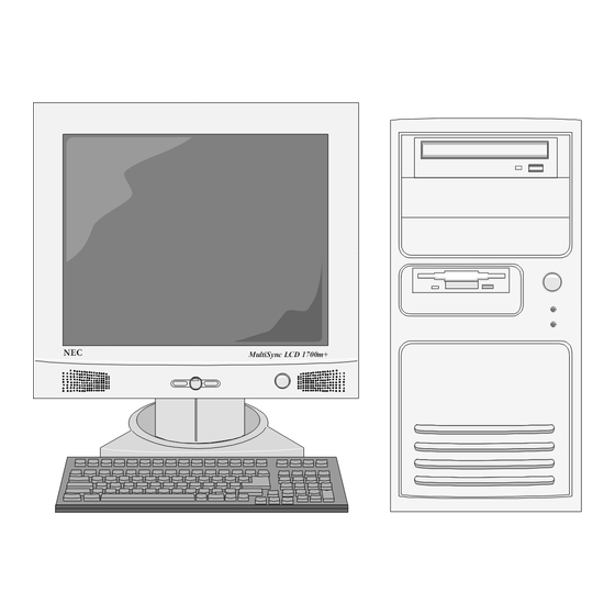
COULTER LH 700 Series Configuration (117 pages)
Brand:
COULTER
| Category:
Desktop
| Size: 1 MB
Table of Contents
Table of Contents
4
1 Introduction
10
Document Layout
10
Scope
10
Function
10
Operating Environment
10
Transporting
11
Safety Precautions and General Service Information
11
Hazard Conventions
12
Definition of Acronyms and Terms
12
Table 1-1: Acronyms and Terms Used in this Document
12
Component Description and Configurations
15
Circuit Cards
15
2 System Card (Motherboard)
15
Table 2-1: System Card(S) Configuration
15
Intel Desktop Board D815EEA
16
Input and Output Connections
16
Jumper Settings
16
Table 2-2: Circuit Card Locations on the Intel Desktop Board D815EEA
16
Table 2-3: J7C1 - Bios Setup Configuration Jumper Settings
17
Figure 2-1: Intel Desktop Board D815EEA
17
AMI Olympus II ( Series 821 )
18
Input and Output Connections
18
Table 2-4: Connector and Circuit Card Locations on AMI Olymus II
18
JP4 Front Panel Connector
19
Table 2-5: J7C1 - Bios Setup Configuration Jumper Settings
19
Figure 2-2: AMI Olympus II - Series 821
19
3 Video Card
21
Table 3-1: Video Card Configuration
21
Matrox ® G550 Dual-DVI AGP Video Card
22
Input and Output Connections
22
Figure 3-1: Mattrox G550 AGP Video Card
22
Matrox G550 AGP Video Card Software Installation and Configuration
23
4 Modem Card
24
Table 4-1: Modem Card Configuration
24
US Robotics 56Kb Card - Model 3CP5610A
25
Input and Output Connections
25
US Robotics 3CP5610A 56KB Card Software Installation and Configuration
25
Figure 4-1: US Robotics 3CP5610A 56K Pro Modem Card
25
5 Multi-Port Serial Card(S)
26
Table 5-1: Multi-Port Serial Card(S) Configuration
26
Equinox SST-4/8P Multiport Serial Card
27
Input and Output Connections
27
Equinox SST-4/8P Card Software Installation
27
Figure 5-1: Equinox SST-4/8P Multiport Serial Card
27
6 SCSI Interface Card(S)
28
Table 6-1: SCSI Interface Card Configuration
28
Adaptec 2930U
29
Input and Output Connections
29
Adaptec 2930U Card Installation and Software Configuration
29
Figure 6-1: Adaptec AHA-2930CU Card
29
Internal Drives
30
7 Floppy Drive
30
Table 7-1: Floppy Drive(S) Configuration
30
Sony 3 1/2 Floppy Drive
31
Input and Output Connections
31
Figure 7-1: TEAC FD-235HF 3 1/2 Floppy Drive Hardware Configuration
31
8 Hard Drive
32
Table 8-1: Hard Drive(S) Configuration
32
Quantum Fireball Plus as Hard Drive
33
Input and Output Connections
33
Jumper Settings
33
Figure 8-1: Quantum Fireball Plus as Hard Drive Hardware Configuration
33
Maxtor Diamondmaxplus D740X Hard Drive
34
Input and Output Connections
34
Jumper Settings
34
9 CD/DVD Drive
35
Table 9-1: CD-ROM Drive(S) Configuration
35
Toshiba DVD-ROM SD-M1402
36
Input and Output Connections
36
Figure 9-1: Toshiba SD-M1402 DVD-ROM Hardware Configuration
36
Yamaha 2200EZ CD-R/W Drive
37
Input and Output Connections
37
Figure 9-2: Yamaha 2200EZ CD-R/W
37
Peripherals
38
10 Monitor
38
Table 10-1: LH 700 Series Workstation Monitors
38
NEC Multisync LCD 1700M
39
Input and Output Connections
39
Software Settings
39
Figure 10-1: NEC Multisync LCD 1700M+ - Rear View
39
Monitor Settings
40
Table 10-2: Onscreen Menu Function for NEC Multisync LCD 1700M
40
Figure 10-2: NEC Multisync LCD 1700M+ Controls
40
11 Barcode Reader ( Handheld )
42
Welch allen IT3800 Barcode Scanner
42
Input and Output Connections
42
Hardware Configuration
42
Software Configuration
42
Table 11.1-1: Default Welch allen IT3800 Barcode Scanner Configuration
42
Table 11.1-2: Configuration Options for the Welch allen IT3800 Barcode Scanner
43
12 Uninterruptible Power Supplies (UPS)
45
APC Back-UPS® 650
45
Connect Battery
45
APC Back-UPS 650 Hardware Setup
45
APC Back-UPS 650 Software Configuration
46
Figure 12-1: Power Options Properties
47
Figure 12-2: UPS Selection Dialog Box
47
Figure 12-3: UPS Configuration Dialog Box
48
13 Iomega® Jaz® Drive
49
Setup
49
Software
50
14 Bios
50
Intel BIOS Used with the D815EEA System Board
51
Accessing the BIOS Setup
51
BIOS Setup
51
Main Tab
51
Advanced Tab
52
Security
54
Power
55
Boot
55
Exit
55
AMI BIOS Use with the AMI Olympus (Series 821) System Board
56
Accessing the BIOS Setup
56
BIOS Setup
56
Main Tab
56
Advanced Tab
57
Chipset
63
Pcipnp
64
Power
64
Boot
65
Security
65
Exit
66
15 Operating System
67
Microsoft Windows 2000 Professional
67
Overview
67
Control Panel
67
Figure 15-1: Control Panel
67
Figure 15-2: Date & Time Dialog Box
68
Figure 15-3: Regional Options
69
Printers
70
Figure 15-4: Select System Locale Dialog
70
Administrative Tools
72
Figure 15-5: Administrative Tools
73
Figure 15-6: Computer Management Screen - Disk Management Selected
74
Additional Programs and Service Functions
75
16 LH 700 Series Workstation Application
77
LH 700 Series Workstation Imaging Procedure
77
Parts Required
77
Procedure
77
LH 700 Series Workstation Update Procedure
80
Parts Required
80
Procedure
80
Save and Restore Configuration
80
Save Configuration
80
Restore Configuration
81
Archive ( Save ) Complete Database
82
Restore
83
Registry
83
Database
84
List Mode Data
84
Slidemaker Software Download
86
Slidestainer Software Download
86
17 Support Software
87
Pcanywhere
89
Norton Antivirus
89
18 Online Intelligent Service - Remote Diagnostics
90
Remote Access and Remote Control ( RCS )
90
Requirements
90
Procedure - Instrument Workstation
90
Remote Computer Setup
91
Procedure - Remote
91
Workstation Initiated Diagnostics with Internet Access
92
19 LH 700 Series Workstation Installation Procedure
93
Workstation Components
93
Monitor Including
93
Computer Base Including
93
UPS Including
93
Optional Accessories
93
Installation Requirements
93
Unpacking
94
Voltage Configuration
94
Cable Connections
94
Configuration and Verification
95
Figure 19-1: LH 700 Series Workstation Cable Connections
97
20 Verification Procedures
99
Verification Procedures
99
LH 700 Series Workstation Functional Verification
99
LH 700 Series Workstation Hardware Verification
100
Display Verification
101
Host Interface Communication Verification
102
Remote Diagnostics Verification
103
UPS Verification
104
LH 700 Series Workstation to Analytical Station Communication Verification
105
Maintenance and Troubleshooting
106
21 Replacement Procedures
106
22 Maintenance
107
Barcode Scanner
107
Computer Base
107
Monitor
107
Keyboard
107
Mouse
107
23 Troubleshooting
108
Passwords
108
Troubleshooting Problems During Power on Self Test (POST)
108
Table 23.1-1: Pre-Assigned LH 700 Series Workstation Passwords
108
Table 23.2-1: D815EEA BIOS Beep Codes
108
Table 23.2-2: D815EEA BIOS LED Codes
109
Table 23.2-3: D815EEA POST Error Messages
109
LH 700 Series Workstation Does Not Boot and no Errors Are Displayed
110
Table 23.3-1: System Does Not Boot and Fan Is off
111
Table 23.3-2: System Does Not Boot and Fan Is on
111
Troubleshooting RCS
113
Dial Tone Is Not Audible
113
Dial Tone Is Audible
113
Table 23.4-1: RCS Connection Failure -- no Dial Tone
113
Table 23.4-2: RCS Connection Failure with Dial Tone
113
Troubleshooting Errors While Operating the LH 700 Series Workstation Installation
114
24 Quick Reference
115
Quick Reference
115
Part Numbers
115
LH 700 Series Workstation Components
115
Table 24.1-1: Part Numbers
115
Configuration Summary
117
Table 24.2-1: Hardware Configurations of the LH 700 Series Workstation
117
Table 24.2-2: Software Configurations of the LH 700 Series Workstation
117
Advertisement
Advertisement
Related Products
COULTER Categories
Measuring Instruments
Desktop
More COULTER Manuals
Login
Sign In
OR
Sign in with Facebook
Sign in with Google
Upload manual
Upload from disk
Upload from URL