Sign In
Upload
Manuals
Brands
Copeland Manuals
Measuring Instruments
RLDS
Copeland RLDS Manuals
Manuals and User Guides for Copeland RLDS. We have
1
Copeland RLDS manual available for free PDF download: Installation And Operation User Manual
Copeland RLDS Installation And Operation User Manual (96 pages)
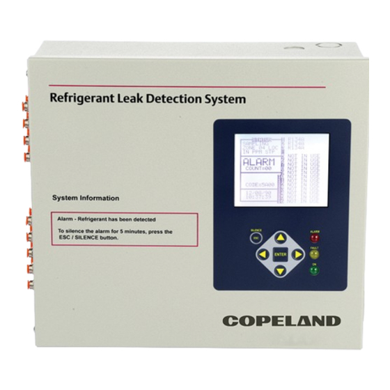
Refrigerant Leak Detection System
Brand:
Copeland
| Category:
Measuring Instruments
| Size: 8 MB
Table of Contents
Table of Contents
3
Introduction
8
How to Use this Manual
8
Notes
8
Safety Precautions
8
AC Power Supply
8
Protective Grounding
8
Explosive Atmosphere
8
Proper Exhaust Venting
8
Working Inside Instrument
8
Misuse and Modifications to the Instrument
9
In Case of Malfunction
9
RLDS Fusing
9
Installation Category
9
Altitude Limit
9
Cleaning
9
Warning and Caution Conventions
9
Warning
9
Caution
9
Important
9
Functional Overview
10
General Description
10
Communication Options
10
Understanding Monitoring Levels
10
Response to the Presence of Multiple Refrigerants
11
Suggested Location of Sampling Points
11
RLDS Hardware Specifications
12
Rlds Installation
14
RLDS - Installation Considerations
14
Warnings and Cautions
14
Inspection
15
Monitor Location
15
Mounting Instructions
15
RLDS - Connecting Gas Sample Lines
16
Overview
16
Tubing Considerations
16
Connecting Purge Line
17
Connecting Exhaust Line
17
Connecting Sample Intake Lines
17
Considerations
18
Installing an Optional Splitter Kit
18
Connecting the Water Trap
18
RLDS Interior Components
19
RLDS Electrical Wiring
19
Warnings and Cautions
20
Connecting Communication Devices
21
E2 MODBUS Direct Support for RLDS
21
Network Connection to E2
21
COM Port Associations - E2 Versions 3.XX and below
21
COM Port Associations - E2 Versions 4.0 and above
21
E2 Termination
22
E2 Setup of RLDS
22
Set up Network Ports
22
Add and Connect RLDS
22
E2, Einstein, and REFLECS Controllers (the RLDS Gateway Board)
23
Powering the Gateway Board
24
Gateway Board Networking
24
Changing Terminator Switch Settings
25
RLDS Node Address
25
Connecting to an E2, Einstein, or REFLECS Site Controller
25
Connecting the Gateway Board to the E2, Einstein, or REFLECS Network
26
Wire Connection
26
Setting the Board Numbering Dip Switch
26
Setting the Baud Rate Dip Switches
27
Setting the RS485 I/O Termination Jumpers
27
Gateway Board Status Leds
28
The General Status LED
28
The Alarm LED
28
RS485 I/O Network Status LED
28
Receiver Bus Network Status LED
28
Integrating with Building Management Systems
28
Connecting to a Building Management System
29
Terminating Multiple Monitors
30
PC Software
31
Operation
31
Saving and Sending Programs
32
Trend Data
32
Converting the TREND Text File to a Microsoft Excel File
32
Saving and Printing Screens and Logs
32
USB Type Laptops
32
Optional Current Loop Interfaces
32
Optional 4-20 Ma DC Outputs
32
Ma DC Connections
34
Rlds - Connecting External Alarms
35
Overview
35
Connection
35
Programming Setup and Ui Navigation for Rlds - Display Screens
37
Initial Power up
37
Data Display Screen
37
Navigate to the First Setup Screen
37
Navigate to the Second Setup Screen
38
Location
38
Number of Zones Installed
38
Alarm Acknowledge (Ack) - Mode
38
Audible Alarm
38
Zone Hold
39
Detection Limit
39
Loop Mode
39
Loop2 Factor
39
Re-Zero Mode
39
Navigating to the Third Setup Screen
40
Baud Rate
40
Node Address
40
Password
40
Additional Service Features
40
Service Timeout
41
DEG Digipot
41
Node Address
41
Sensor Temperature Coefficient (for Factory Use Only)
41
Password
41
Acquiring Temperature Coefficient (Factory Use Only)
41
R Digipot
41
Establishing the CO2 Baseline
42
General Operation of Rlds - Ui
43
Functional Overview
43
The Zone Setup Screen
43
Location
43
Gas/Refrigerant Type
43
Distance + EXH
43
Temperature at Zone
43
Current Detection Reading
43
Log Interval
44
Navigating to the Second Zone Setup Screen
44
Leak Level
44
Spill Level
44
Evacuation Level
44
Resetting the Peak PPM Value
44
Alarm Conditions
44
Fault Conditions
45
Alarms
45
Functional Overview
45
Responding to Alarms
45
Alarm Summary Screen
45
Alarm Detail Screen
45
Acknowledging Alarms
46
Silencing an Alarm
46
Clearing the Alarm Even Log
46
System Faults
47
Functional Overview
47
Navigating to the Fault Screen
47
Critical Faults
47
Non-Critical Faults
48
Reset to Factory Default Settings
48
Clearing System Faults
48
Viewing Fault Log
49
Viewing Flow Log
49
The Trend Screen
49
Navigating to the Trend Screen
49
The Calibration Screen
50
Overview
50
Navigating to the Calibration Screen
50
Calibration Procedure
50
Adjusting Calibration Factor
50
CO2 Atmospheric Concentration (RLDS-CO2 Units Only)
50
Programming New Gases
51
Zone Hold Mode
51
The Diagnostic Screen
52
Navigating to the Diagnostic Screen
52
Diagnostic Screen
52
Diagnostic Options and Controls
52
Diagnostic Screen Overview
53
Quick Setups for Hand-Held Terminal (Hht)
54
Time/Date Setup
54
Zone Setup
54
General Configuration 1 Screen
54
General Configuration 2 Screen
54
Zone Config Screen 1
55
Zone Config Screen 2
55
STATUS OPTION Screen
56
Zone Status Screen
56
Acknowledging Alarms
56
General Controller (CTRL STATUS) Screen
56
Hand-Held Terminal (Hht) for Use with the Gateway and Rlds Controller
57
HHT Key Operations
57
Main Screens
58
Home Screen (F1 Screen)
58
RLDS Enable Screen
58
SELECT RLDS Screen (F2 Screen)
58
Operation Select (OPTION) Screen
59
RLDS STATUS (STATUS OPTION) Screen
59
RLDS FAULTS (SYSTEM FAULTS) Screen
59
RLDS Configuration Option (CONFIG OPTION) Screen
60
General Configuration 1 Screen
60
General Configuration 2 Screen
60
Zone Config Screen 1
61
Zone Config Screen 2
61
Time/Date Screen
62
Calibrate Gas Screen 1
62
Calibrate Gas Screen 2
62
Calibrate Gas Screen 3
62
Calibrate Gas Screen 3 Continued
62
STATUS OPTION Screen
63
Zone Status Screen
63
General Controller (CTRL STATUS) Screen
63
DIAGNOSTICS Screen 1: Sensor Data Register
64
Screen 2: Sensor Data Register
64
Screen 3: Sensor Data Register
64
Screen 4: Sensor Data Register
64
Screen 5: Sensor Data Register
64
Screen 6: Sensor Data Register
65
Screen 7: Communication Statistics
65
Rlds Setup on Reflecs, E2, Einstein, and Supervisory Controllers
66
REFLECS Setup for RLDS
66
E2 Version 3.01 and below Setup for RLDS (Without Gateway)
66
Supervisory Controller Setup for RLDS
67
Adding Application
68
Edit Application
68
General
68
Zone Setup
68
Zone Alarms Leak/Spill/Evac
68
Rlds Maintenance
69
Warnings and Cautions
69
Replacement Parts Overview
69
Replacement Parts and Optional Accessories
71
Replacement Parts
71
Optional Accessories
72
Troubleshooting
73
Appendix A: Recommended Refrigerant Gas Alarm Settings
74
Appendix B: Rs-485 Communications Protocol
78
Appendix C: Fault Codes
93
Appendix D: System Menu Map
94
Advertisement
Advertisement
Related Products
Copeland 085-0160-00
Copeland 250-5000
Copeland Categories
Controller
Air Compressor
Thermostat
Measuring Instruments
Control Unit
More Copeland Manuals
Login
Sign In
OR
Sign in with Facebook
Sign in with Google
Upload manual
Upload from disk
Upload from URL