Sign In
Upload
Manuals
Brands
Comtec Manuals
Transceiver
MBT-4000
Comtec MBT-4000 Manuals
Manuals and User Guides for Comtec MBT-4000. We have
1
Comtec MBT-4000 manual available for free PDF download: Installation And Operation Manual
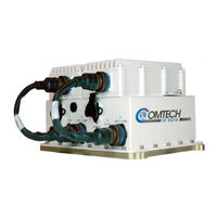
Comtec MBT-4000 Installation And Operation Manual (83 pages)
Multi-Band Transceiver System
Brand:
Comtec
| Category:
Transceiver
| Size: 1 MB
Table of Contents
Table of Contents
3
About this Manual
9
Cautions and Warnings
9
Copyright
9
Patents and Trademarks
9
Preface
9
Class I Pluggable Equipment Type A-Protective Earthing
10
Electromagnetic Compatibility (EMC) Compliance
10
EN 55022 -1998 Compliance
10
Low Voltage Directive (LVD)
10
Regulatory Compliance
10
Federal Communications Commission (FCC)
11
Galvanic Isolator Use
11
International Symbols
11
Restricted Access Location
11
Comtech Headquarters
12
Limitations of Warranty
12
Product Support
12
Warranty Policy
12
Exclusive Remedies
13
Chapter 1. Introduction
15
Overview
15
Functional Description
15
Figure 1-1. MBT-4000 Multi-Band RF Transceiver
15
Common Features
16
Figure 1-2. MBT-4000 Operational Schematic
16
Options
17
System Overview
17
Figure 1-3. Operational Diagram for Dual-Base (Chain) Redundancy Option
17
Summary of Specifications
18
Environmental & Physical
18
BUC-4000 Block up Converter ODU
18
BDC-4000 Block down Converter ODU
19
Dimensional Envelope
20
Figure 1-4. MBT-4000 Dimensional Envelope
20
Chapter 2. Installation
22
Unpacking and Inspection
22
Installation
23
Operation
23
Chapter 3. External Connectors
24
External Connectors Overview
24
Figure 3-1. MBT-4000 External Connectors
24
MBT-4000 External Connectors
25
Table 3-1. MBT-4000 External Connectors
25
3.2.1 if Signal Side Connectors
26
Power (J1)
26
Table 3-2. POWER (J1) Pin Connections
26
Comm (J2)
27
Table 3-3. COMM (J2) Connector Pinouts
27
Unit 1 Comm (J3)
28
Table 3-4. UNIT 1 COMM (J3) Connector Pinouts
28
Figure 3-2. Unit 1 Base Module to Converter Module Connection
28
IF Switch (J4)
29
Ext Ref (External Reference) (J5)
29
Table 3-5. if Switch (J4) Connector Pinouts
29
Unit 2 Comm (J6)
30
Table 3-6. UNIT 2 COMM (J6) Connector Pinouts
30
Figure 3-3. Unit 2 Base Module to Converter Module Connection
30
Ground Connector
31
If in (J4, Buc-4000 Only)
31
Comm (J6, Buc-/Bdc-4000)
31
Table 3-7. UNIT 2 COMM (J6) Connector Pinouts
31
If out (J4, Bdc-4000 Only)
32
3.2.1.11 RF Signal Side Connectors
32
Redundant Loop (J7)
32
Table 3-8. REDUNDANT LOOP (J7) Connector Pinouts
32
Aux Comm 2 (J8)
33
Aux Comm 1 (J9)
33
Table 3-9. AUX COMM 2 (J8) Connector Pinouts
33
Table 3-10. AUX COMM 1 (J9) Connector Pinouts
33
Rf Switch (J10)
34
Rf out (J5, Buc-4000 Only)
34
Rf in (J5, Bdc-4000 Only)
34
Table 3-11. RF Switch (J10) Connector Pinouts
34
Chapter 4. System Operating Parameters
36
Overview
36
Remote Configuration, Monitoring and Control
36
Block up Converter Module (BUC-4000) Operating Parameters
36
Table 4-1. BUC-4000 C-, X-, Ku-, and Ka-Band Operating Parameters
36
Block down Converter Module (BDC-4000) Operating Parameters
37
Monitoring Operations Via the LED Indicators
37
Table 4-2. BDC-4000 C-, X-, KU-, and Ka-Band Operating Parameters
37
Figure 4-1. MBT-4000 Multi-Band RF Transceiver LED Indicators
37
Chapter 5. Flash Upgrading
39
Overview
39
Flash Updating Via Internet
39
Figure 5-1. Flash Update Via Internet
39
Firmware File Transfer Procedure
40
Flash Upgrade Procedure
41
Appendix A. Remote Control
46
Overview
46
Basic Protocol
47
Packet Structure
47
Start of Packet
48
Target Address
48
Address Delimiter
48
Instruction Code
48
Instruction Code Qualifier
49
Optional Message Arguments
50
End of Packet
50
Remote Commands and Queries
51
Appendix B. Faults/Events
70
LED Status Indicators
70
Figure B-1. MBT-4000 LED Indicators
70
Faults/Events
71
Summary Faults
71
Table B-1. MBT-4000 Summary Faults
71
Table B-2. BDC-4000/BUC-4000 Summary Faults
71
Figure B-2. Faulted System Example
71
B.2.2 Configurable Summary Faults
72
Table B-3. MBT-4000 Configurable Summary Faults
72
B.2.3 Informational Events
73
Table B-4. BDC-4000 Configurable Summary Faults
73
Table B-5. MBT-4000 Informational Events
73
Table B-6. BDC-4000/BUC-4000 Informational Events
73
Appendix C. Redundancy Configuration / Operation
74
Overview
74
Single-Base Redundancy Operation
74
Dual-Base Redundancy Operation
75
Figure C-1. Dual-Base Chain Redundant Operation
76
Figure C-2. Dual-Base Single Redundant Operation
77
Figure C-3. Dual-Base Dual Redundant Operation
78
External Fault Monitoring
80
LNA Power Supply Current Monitoring
80
Gain Equalization of Redundant Units
81
Operational Configuration Commands
81
Advertisement
Advertisement
Related Products
Comtec Categories
Network Router
Printer
Wireless Access Point
Transceiver
Dash Cameras
More Comtec Manuals
Login
Sign In
OR
Sign in with Facebook
Sign in with Google
Upload manual
Upload from disk
Upload from URL