Table of Contents
Advertisement
Quick Links
IMPORTANT NOTE: The information contained in this document supersedes all previously published
information regarding this product. Product specifications are subject to change without prior notice.
MBT-4000
Multi-Band Transceiver System
Installation and Operation Manual
Part Number MN/MBT4000.IOM
June 8, 2022
Part Number MN/MBT4000.IOM Revision 6
Revision 6
Advertisement
Table of Contents

Summary of Contents for Comtec MBT-4000
- Page 1 MBT-4000 Multi-Band Transceiver System Installation and Operation Manual Part Number MN/MBT4000.IOM Revision 6 June 8, 2022 IMPORTANT NOTE: The information contained in this document supersedes all previously published information regarding this product. Product specifications are subject to change without prior notice.
- Page 2 MBT-4000 Multi-Band Transceiver System Revision 6 Copyright © 2022 Comtech Satellite Network Technologies. All rights reserved. Printed in the USA. Comtech Satellite Network Technologies, 2114 West 7th Street, Tempe, Arizona 85281 USA, 480.333.2200, FAX: 480.333.2161 Revision History Date Description Initial Release.
-
Page 3: Table Of Contents
MBT-4000 Multi-Band Transceiver System Revision 6 Table of Contents TABLE OF CONTENTS ......................1 LIST OF TABLES........................4 LIST OF FIGURES ........................4 PREFACE........................... I About this Manual ............................i Cautions and Warnings ..........................i Patents and Trademarks ..........................i Copyright ..............................i Regulatory Compliance ..........................ii... - Page 4 MBT-4000 Multi-Band Transceiver System Revision 6 Summary of Specifications......................1–4 1.6.1 Environmental & Physical ....................1–4 1.6.2 BUC-4000 Block Up Converter ODU .................. 1–4 1.6.3 BDC-4000 Block Down Converter ODU ................1–5 Dimensional Envelope ........................ 1–6 CHAPTER 2. INSTALLATION.....................2–1 Unpacking and Inspection......................2–1 Installation...........................
- Page 5 MBT-4000 Multi-Band Transceiver System Revision 6 Monitoring Operations via the LED Indicators............... 4–2 CHAPTER 5. FLASH UPGRADING ..................5–1 Overview ............................5–1 Flash Updating via Internet ....................... 5–1 5.2.1 Firmware File Transfer Procedure ..................5–2 Flash Upgrade Procedure......................5–3 APPENDIX A. REMOTE CONTROL................... A–1 Overview .............................
- Page 6 Figure 3-2. Unit 1 Base Module to Converter Module Connection ............3–5 Figure 3-3. Unit 2 Base Module to Converter Module Connection ............3–7 Figure 4-1. MBT-4000 Multi-Band RF Transceiver LED Indicators ............4–2 Figure 5-1. Flash Update via Internet ....................... 5–1 Figure B-1.
- Page 7 MBT-4000 Multi-Band Transceiver System Revision 6 Units of Measurement Unit / Symbol Definition Ω Ampere Alternating Current bits per second ˚C Celsius (degrees) Direct Current Hertz kiloHertz decibel Decibels relative to the carrier Decibel-milliwatts ˚F Fahrenheit (degrees) Kbps Kilobit per second...
- Page 8 MBT-4000 Multi-Band Transceiver System Revision 6 BLANK PAGE Table of Contents TOC-6 MN/MBT4000.IOM...
-
Page 9: Preface
PREFACE About this Manual This manual gives installation and operation information for the Comtech Satellite Network Technologies, Inc. (Comtech) MBT-4000 Multi-Band Transceiver System. Anyone who installs or operates the unit must read this manual. Cautions and Warnings IMPORTANT or NOTE indicates information critical for proper equipment function. -
Page 10: Regulatory Compliance
MBT-4000 Multi-Band Transceiver System Revision 6 Regulatory Compliance Electromagnetic Compatibility (EMC) Compliance This is a Class A product. In a domestic environment, it may cause radio interference that requires the user to take adequate protection measures. EN 55022 –1998 Compliance This equipment meets the radio disturbance characteristic specifications for information technology equipment as defined per EN 55022 1998. -
Page 11: Galvanic Isolator Use
MBT-4000 Multi-Band Transceiver System Revision 6 In Sweden: “Apparaten skall anslutas till jordat uttag” Galvanic Isolator Use Equipment that is connected to protective ground via grounded wall socket and/or via other equipment and at the same time connected to cable TV networks may in some cases be a risk of fire. -
Page 12: Product Support
MBT-4000 Multi-Band Transceiver System Revision 6 Product Support For all product support, please call: +1.240.243.1880 +1.866.472.3963 (toll free USA) Comtech Headquarters http://www.comtechefdata.com Comtech Satellite Network Technologies, Inc. 2114 West 7th Street Tempe, Arizona USA 85281 +1.480.333.2200 Warranty Policy Comtech products are warranted against defects in material and workmanship for a specific period from the date of shipment, and this period varies by product. -
Page 13: Exclusive Remedies
MBT-4000 Multi-Band Transceiver System Revision 6 The warranty does not cover damage or loss incurred in transportation of the product. The warranty does not cover replacement or repair necessitated by loss or damage from any cause beyond the control of Comtech, such as lightning or other natural and weather-related events or wartime environments. - Page 14 MBT-4000 Multi-Band Transceiver System Revision 6 Notes: Preface...
-
Page 15: Chapter 1. Introduction
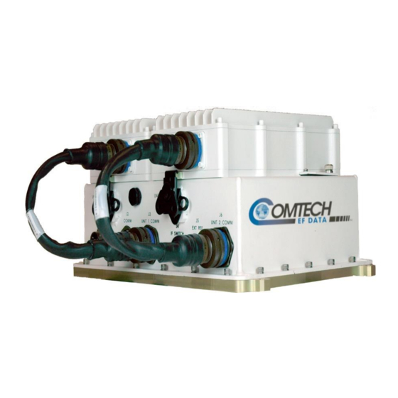
Chapter 1. INTRODUCTION Overview Comtech Satellite Network Technologies, Inc (Comtech) MBT-4000 Multi-Band RF Transceiver, shown in Figure 1-1, is designed to perform C-, X-, or Ku-Band RF to L-Band down conversion and L-Band to C-, X-, or Ku- or Ka-Band RF up conversion. -
Page 16: Common Features
Flexible configuration: 2 Ups 2 Downs 1Up / 1 Down Figure 1-2 depicts the operation schematic for a typical MBT-4000 application. LBC-4000 BUC-4000C 70 MHz L-Band From IF In RF Out IF In To C-Band HPA... -
Page 17: Options
Dual-Base (Chain) Redundancy Operation (see Figure 1-3) System Overview The MBT-4000 Multi-Band Transceiver System is constructed in a modular configuration. Figure 1-3 illustrates the key components of this configuration. Common to the configuration for any frequency band of operation is a base module, which provides the Monitor and Control (M&C), Power Supply, and Reference function. -
Page 18: Summary Of Specifications
-40º 122ºF (-40º to 50ºC) Operating – Temperature IDU: LBC-4000 14º 122ºF (-10º to 50ºC) – Non-operating ODU: MBT-4000 -58º 160ºF (-50º to 71ºC) – Operational Humidity 95 non-condensing Operational Altitude 10,000 ft above sea level – Prime Power 260 VAC, 47-63 Hz Either 5 MHz or 10 MHz 5 dBm optional... -
Page 19: Bdc-4000 Block Down Converter Odu
1.6.3 BDC-4000 Block Down Converter ODU Output Frequency Range 950 – 2000 MHz BUC-4000C 3400 – 4200 MHz BUC-4000X 7250 – 7750 MHz BUC-4000Ku 10.95 – 12.75 GHz Input Frequency (by model) BUC-4000Ka 20.20 – 21.20 GHz 17.70 – 18.70 GHz (optional band) 18.70 –... -
Page 20: Dimensional Envelope
Dimensional Envelope Figure 1-4. MBT-4000 Dimensional Envelope 1–6... - Page 21 Notes: 1–7...
-
Page 22: Chapter 2. Installation
Cut the tape at the top of the carton indicated by OPEN THIS END. Remove the cardboard/foam space covering the MBT-4000. Remove the MBT-4000 and manual from the carton. Save the packing material for storage or reshipment purposes. Inspect the equipment for any possible damage incurred during shipment. -
Page 23: Installation
Base unit, allowing removal and replacement of the existing modules with appropriate band-specific modules. Operation Once all pertinent connections have been made between the MBT-4000 and other equipment, refer to Chapter 4. SYSTEM OPERATING PARAMETERS for further information. Installation 2–2... -
Page 24: Chapter 3. External Connectors
As shown in Figure 3-1, connectors provided on the MBT4000 Multi-Band Transceiver System provide all necessary external connections between the the transceiver and other equipment. Note: This figure depicts an MBT-4000 configuration with (1) BUC-4000 Block Up Converter Module and (1) BDC-4000 Block Down Converter Module installed. -
Page 25: Mbt-4000 External Connectors
MBT-4000 Multi-Band Transceiver System Revision 6 MBT-4000 External Connectors Table 3-1 summarizes the external connections and identifies the chapter sections providing connector pinout information. Table 3-1. MBT-4000 External Connectors Signal Side Module Name Sect. Function (Sect.) Power In POWER 3.2.1.1... -
Page 26: 3.2.1 If Signal Side Connectors
MBT-4000 Multi-Band Transceiver System Revision 6 3.2.1 IF Signal Side Connectors 3.2.1.1 POWER (J1) Table 3-2. POWER (J1) Pin Connections AC Power Signal LINE NEUTRAL NOTE - Mating Connectors: COMTECH P/N CN/MS-STPG03F02 (ITT Cannon KPT06B-12-3S) DC Power Signal B, C... -
Page 27: Comm (J2)
MBT-4000 Multi-Band Transceiver System Revision 6 3.2.1.2 COMM (J2) Table 3-3. COMM (J2) Connector Pinouts Signal RS 485 Rx+ RS 485 Rx- RS 485 Tx+ RS 485 Tx- RS 232 RD RS 232 TD SUM FLT COMM SUM FLT NO... -
Page 28: Unit 1 Comm (J3)
3.2.1.3 UNIT 1 COMM (J3) The J3 UNIT 1 COMM connector is used for connecting the MBT-4000 Base Module Unit 1 section to the J6 COMM connector featured on both the BUC-4000 Block Up Converter and BDC-4000 Block Down Converter Modules via the 15-15 Power &... -
Page 29: If Switch (J4)
MBT-4000 Multi-Band Transceiver System Revision 6 3.2.1.4 IF Switch (J4) Table 3-5. IF Switch (J4) Connector Pinouts Signal POS 1 IF POS 2 IF POS 1 IND IF POS 2 IND IF NOTE - Mating Connectors: COMTECH P/N CN/MS3116J10-6P (Cannon MS3116J10-6P) 3.2.1.5... -
Page 30: Unit 2 Comm (J6)
3.2.1.6 UNIT 2 COMM (J6) The J6 UNIT 2 COMM connector is used for connecting the MBT-4000 Base Module Unit 2 section to the J6 COMM connector featured on both the BUC-4000 Block Up Converter and BDC-4000 Block Down Converter Modules, via the 15-15 Power &... -
Page 31: Ground Connector
The J6 COMM connector, featured on both the BUC-4000 Block Up Converter and BDC-4000 Block Down Converter Modules, is used for connecting the module to the MBT-4000 Base Module J3 UNIT 1 COMM or J6 UNIT 2 COMM connectors via the 15-15 Power & Signal Harness (COMTECH P/N CA/WR10963-1), as shown in Figure 3-2 and Figure 3-3. -
Page 32: If Out (J4, Bdc-4000 Only)
3.2.1.11 RF Signal Side Connectors 3.2.1.12 REDUNDANT LOOP (J7) The J7 REDUNDANT LOOP connector is used to connect the MBT-4000 Base Module, via the Redundant Loop Bus Cable (COMTECH P/N CA/WR11224), to another base unit for a dual base (redundant) setup. -
Page 33: Aux Comm 2 (J8)
MBT-4000 Multi-Band Transceiver System Revision 6 3.2.1.13 AUX COMM 2 (J8) Table 3-9. AUX COMM 2 (J8) Connector Pinouts Signal AUX Rx + B AUX Rx – B AUX Tx + B AUX Tx – B +12.6V LNA B 02 A/Fault... -
Page 34: Rf Switch (J10)
MBT-4000 Multi-Band Transceiver System Revision 6 3.2.1.15 RF SWITCH (J10) Table 3-11. RF Switch (J10) Connector Pinouts Signal POS 1 RF POS 2 RF POS 1 IND RF POS 2 IND RF NOTE – Mating Connectors: COMTECH P/N CN/MS3116J10-6P (Cannon MS3116J10-6P) 3.2.1.16 RF OUT (J5, BUC-4000 ONLY) - Page 35 MBT-4000 Multi-Band Transceiver System Revision 6 Notes: External Connectors 3–12 MN/MBT4000.IOM...
-
Page 36: Chapter 4. System Operating Parameters
BDC-4000 Block Down Converter, are provided in this chapter. Remote Configuration, Monitoring and Control Remote monitoring and control (M&C) of the MBT-4000 is possible via use of a remotely- connected PC or dumb terminal. From this location, the user may issue commands and queries to configure, control, and monitor one or more MBT-4000 systems. -
Page 37: Block Down Converter Module (Bdc-4000) Operating Parameters
Figure 4-1 illustrates the location of the LED Indicators. Located on the top of the MBT-4000’s Base Module under a pivoting protective plate, the LEDs may be viewed by loosening the thumbscrew that keeps the plate in place;... - Page 38 MBT-4000 Multi-Band Transceiver System Revision 6 Notes: System Operating Parameters 4–3 MN/MBT4000.IOM...
-
Page 39: Chapter 5. Flash Upgrading
Comtech MBT-4000 Multi-Band Transceiver System. This is a technical document intended for users – i.e., earth station engineers, technicians, and operators – responsible for the operation and maintenance of the MBT-4000. This chapter also assumes that the user has familiarity with Microsoft Windows-based operating systems. -
Page 40: Firmware File Transfer Procedure
Firmware File Transfer Procedure 1. Identify the reflashable product, firmware number, and version for download: Using serial remote control, the current MBT-4000 firmware revision can be determined with the following query: <0/FRW? (detailed). 2. Create a temporary directory (folder) on a user-provided external PC. -
Page 41: Flash Upgrade Procedure
MBT-4000 Multi-Band Transceiver System Revision 6 4. Unzip the files in the temporary folder on the PC, PC, then, verify the success of the file extraction using the dir command. At least four files should be extracted: ReleaseNotes_vX-X-X.pdf, where “X-X-X” denotes the firmware version. - Page 42 MBT-4000 Multi-Band Transceiver System Revision 6 Flash Upgrading 5–4 MN/MBT4000.IOM...
- Page 43 MBT-4000 Multi-Band Transceiver System Revision 6 Flash Upgrading 5–5 MN/MBT4000.IOM...
- Page 44 MBT-4000 Multi-Band Transceiver System Revision 6 The upgrade process has been successfully completed. Flash Upgrading 5–6 MN/MBT4000.IOM...
- Page 45 MBT-4000 Multi-Band Transceiver System Revision 6 Notes: Flash Upgrading 5–7 MN/MBT4000.IOM...
-
Page 46: Appendix A. Remote Control
Overview This appendix describes the protocol and message command set for remote monitor and control of the MBT-4000 Multi-Band Transceiver System (more specifically, the BUC-4000 and BDC-4000 modules). The electrical interface is either an RS-485 multi-drop bus (for the control of many devices) or an RS-232 connection (for the control of a single device), and data is transmitted in asynchronous serial form using ASCII characters. -
Page 47: Basic Protocol
MBT-4000 Multi-Band Transceiver System Revision 6 RS-232 This is a much simpler configuration in which the Controller device is connected directly to the Target via a two-wire-plus-ground connection. Controller-to-Target data is carried, via RS-232 electrical levels, on one conductor, and Target-to-Controller data is carried in the other direction on the other conductor. -
Page 48: Start Of Packet
The BDC and BUC subdevices may also be addressed by appending the corresponding subdevice address. The subdevice address is ‘A1’ for the BUC and ‘A2’ for the BDC. For example, a mute command addressed to a BUC attached to an MBT-4000 at address 0412 will be: <0412A1/MUT=1{CR} The format of the response will be: >0412A1/MUT={CR}{LF}... -
Page 49: Instruction Code Qualifier
MBT-4000 Multi-Band Transceiver System Revision 6 A.5.5 Instruction Code Qualifier This single character further qualifies the preceding instruction code. Code Qualifiers obey the following rules: 1. From Controller-to-Target, the only permitted values are: The = code is used as the assignment operator, and is used to indicate that the... -
Page 50: Optional Message Arguments
MBT-4000 Multi-Band Transceiver System Revision 6 A.5.6 Optional Message Arguments Arguments are not required for all messages. Arguments are ASCII codes for the characters 0 to 9 (ASCII codes 48-57), period (ASCII code 46), and comma (ASCII code 44). A.5.7 End of Packet Controller-to-Target: This is the 'Carriage Return' character (ASCII code 13). -
Page 51: Remote Commands And Queries
MBT-4000 Multi-Band Transceiver System Revision 6 Remote Commands and Queries Where Column ‘C’ = Command; Column ‘Q’ = Query: Columns marked ( ) indicate Command only, Query only, or Command/Query for Instruction Code. Instr Code Page Instr Code Page A-18... - Page 52 CAI=(message OK) CAI?n CAI=nabcd COMM I/O 1=AUX Used to Query the Concise AUX COMM I/O of the MBT-4000 CAI? (received OK, (see description COMM 1 base unit, where: n=1 (AUX COMM 1) or 2 (AUX COMM 2) but invalid arguments...
- Page 53 MBT-4000 Multi-Band Transceiver System Revision 6 Remote Control MN/MBT4000.IOM Command Valid on Arguments Response to Query Response to Description of Arguments Parameter (Instruction MBT, for Command Command (Instruction Query (Note that all arguments are ASCII numeric codes – i.e., Type...
- Page 54 MBT-4000 Multi-Band Transceiver System Revision 6 Remote Control MN/MBT4000.IOM Command Valid on Arguments Response to Query Response to Description of Arguments Parameter (Instruction MBT, for Command Command (Instruction Query (Note that all arguments are ASCII numeric codes – i.e., Type...
- Page 55 MBT-4000 Multi-Band Transceiver System Revision 6 Remote Control MN/MBT4000.IOM Command Valid on Arguments Response to Query Response to Description of Arguments Parameter (Instruction MBT, for Command Command (Instruction Query (Note that all arguments are ASCII numeric codes – i.e., Type...
- Page 56 MBT-4000 Multi-Band Transceiver System Revision 6 Remote Control MN/MBT4000.IOM Command Valid on Arguments Response to Query Response to Description of Arguments Parameter (Instruction MBT, for Command Command (Instruction Query (Note that all arguments are ASCII numeric codes – i.e., Type...
- Page 57 MBT-4000 Multi-Band Transceiver System Revision 6 Remote Control MN/MBT4000.IOM Command Valid on Arguments Response to Query Response to Description of Arguments Parameter (Instruction MBT, for Command Command (Instruction Query (Note that all arguments are ASCII numeric codes – i.e., Type...
- Page 58 MBT-4000 Multi-Band Transceiver System Revision 6 Remote Control MN/MBT4000.IOM Command Valid on Arguments Response to Query Response to Description of Arguments Parameter (Instruction MBT, for Command Command (Instruction Query (Note that all arguments are ASCII numeric codes – i.e., Type...
- Page 59 MBT-4000 Multi-Band Transceiver System Revision 6 Remote Control MN/MBT4000.IOM Command Valid on Arguments Response to Query Response to Description of Arguments Parameter (Instruction MBT, for Command Command (Instruction Query (Note that all arguments are ASCII numeric codes – i.e., Type...
- Page 60 MBT-4000 Multi-Band Transceiver System Revision 6 Remote Control MN/MBT4000.IOM Command Valid on Arguments Response to Query Response to Description of Arguments Parameter (Instruction MBT, for Command Command (Instruction Query (Note that all arguments are ASCII numeric codes – i.e., Type...
- Page 61 Query only. RAI = (message OK) RAI?n RAI=x….x value of Used to Retrieve AUX COMM I/O of the MBT-4000 base unit, RAI? (received OK, (see description COMM I/O n=1 or 2 where: n=1 (Aux Comm 1) or 2 (Aux Comm 2).
- Page 62 MBT-4000 Multi-Band Transceiver System Revision 6 Remote Control MN/MBT4000.IOM Command Valid on Arguments Response to Query Response to Description of Arguments Parameter (Instruction MBT, for Command Command (Instruction Query (Note that all arguments are ASCII numeric codes – i.e., Type...
- Page 63 MBT-4000 Multi-Band Transceiver System Revision 6 Remote Control MN/MBT4000.IOM Command Valid on Arguments Response to Query Response to Description of Arguments Parameter (Instruction MBT, for Command Command (Instruction Query (Note that all arguments are ASCII numeric codes – i.e., Type...
- Page 64 MBT-4000 Multi-Band Transceiver System Revision 6 Remote Control MN/MBT4000.IOM Command Valid on Arguments Response to Query Response to Description of Arguments Parameter (Instruction MBT, for Command Command (Instruction Query (Note that all arguments are ASCII numeric codes – i.e., Type...
- Page 65 MBT-4000 Multi-Band Transceiver System Revision 6 Remote Control MN/MBT4000.IOM Command Valid on Arguments Response to Query Response to Description of Arguments Parameter (Instruction MBT, for Command Command (Instruction Query (Note that all arguments are ASCII numeric codes – i.e., Type...
- Page 66 999999999 arguments) Example: RSN=000000165 Retrieve 24 bytes Query only. RUS? RUS=x….x Utility Status alphanumeric Used to Query the utility status of the MBT-4000 base unit.. (see description for details of Example: arguments) <0001/RUS={cr} >0001/RUS={cr}{lf} ADR=0001{cr} BDR=9600{cr}{lf} Remote Baud SBR=xxxx 4 bytes, Command or Query.
- Page 67 MBT-4000 Multi-Band Transceiver System Revision 6 Remote Control MN/MBT4000.IOM Command Valid on Arguments Response to Query Response to Description of Arguments Parameter (Instruction MBT, for Command Command (Instruction Query (Note that all arguments are ASCII numeric codes – i.e., Type...
- Page 68 MBT-4000 Multi-Band Transceiver System Revision 6 Remote Control MN/MBT4000.IOM Command Valid on Arguments Response to Query Response to Description of Arguments Parameter (Instruction MBT, for Command Command (Instruction Query (Note that all arguments are ASCII numeric codes – i.e., Type...
- Page 69 MBT-4000 Multi-Band Transceiver System Revision 6 Remote Control MN/MBT4000.IOM Command Valid on Arguments Response to Query Response to Description of Arguments Parameter (Instruction MBT, for Command Command (Instruction Query (Note that all arguments are ASCII numeric codes – i.e., Type...
-
Page 70: Appendix B. Faults/Events
As shown in Figure B-1, the LEDs are found on the top of the MBT-4000’s base module, under a protective plate. To view the LEDs, loosen the thumbscrew that keeps the plate in place, then swing the plate away to reveal the LED display window. -
Page 71: Faults/Events
If a Summary Fault occurs on the online unit of a redundant pair, the offline unit will detect the fault and assume online state. In all cases, a corresponding event message will be added to the event log. Table B-1. MBT-4000 Summary Faults Mnemonic Type... -
Page 72: B.2.2 Configurable Summary Faults
MBT-4000 Multi-Band Transceiver System Revision 6 B.2.2 Configurable Summary Faults Configurable Summary Faults operate the same as Summary Faults, except Configurable Summary Faults may be enabled/disabled via remote commands. Table B-3. MBT-4000 Configurable Summary Faults Mnemonic Type Mute Description The IO1A/FAULT input (AUX COMM 1) indicates a fault. -
Page 73: B.2.3 Informational Events
LCS, CLC and LCW commands. B.2.3 Informational Events Informational Events are operation conditions which may be important, but are not considered improper operation and will not cause a converter to mute. Table B-5. MBT-4000 Informational Events Mnemonic Type Mute... -
Page 74: Appendix C. Redundancy Configuration / Operation
Overview The MBT-4000 is designed to operate in both stand-alone and redundant configurations. Every MBT-4000 base contains the circuitry and logic necessary to perform all the functions of a backup controller in either a single base and dual base configuration. -
Page 75: Dual-Base Redundancy Operation
Revision 6 Dual-Base Redundancy Operation The MBT-4000 can support three (3) different Dual-Base redundancy configurations as follows: 1. Chain Redundant: Dual-Base, two (2) BxC per Base, external subsystems (SSPA, LNA, etc.) including asscoaited switch assemblies providing two (2) chain switched 1:1 configurations. -
Page 76: Figure C-1. Dual-Base Chain Redundant Operation
MBT-4000 Multi-Band Transceiver System Revision 6 Redundancy Configuration / Operation MN/MBT4000.IOM Figure C-1. Dual-Base Chain Redundant Operation Redundancy Configuration / Operation C–3 MN/MBT4000.IOM... -
Page 77: Figure C-2. Dual-Base Single Redundant Operation
MBT-4000 Multi-Band Transceiver System Revision 6 Redundancy Configuration / Operation MN/MBT4000.IOM Figure C-2. Dual-Base Single Redundant Operation Redundancy Configuration / Operation C–4 MN/MBT4000.IOM... -
Page 78: Figure C-3. Dual-Base Dual Redundant Operation
MBT-4000 Multi-Band Transceiver System Revision 6 Redundancy Configuration / Operation MN/MBT4000.IOM Figure C-3. Dual-Base Dual Redundant Operation Redundancy Configuration / Operation C–5 MN/MBT4000.IOM... - Page 79 Redundancy Configuration / Operation MN/MBT4000.IOM The two MBT-4000 base units cooperate in monitoring the health of the two (2) or four (4) BxCs (and each other) and, when applicable, external amplifiers, LNAs, LNBs, etc. In case of a fault on...
-
Page 80: External Fault Monitoring
MN/MBT4000.IOM External Fault Monitoring Each MBT-4000 base includes two logic inputs, one per AUX COMM connector, that may be connected to contact closure fault indications of external equipment (usually an SSPA or LNA). Thus, external equipment failure may participate in overall fault indication and redundant switchover operation according to the following rules: 1. -
Page 81: Gain Equalization Of Redundant Units
If a current is detected outside this window, a LNA current fault will be posted, but the supply will not be disabled. Gain Equalization of Redundant Units Gain equalization in an MBT-4000 system is accomplished by issuing individual attenuation settings to the specific BxCs. Operational Configuration Commands In automatic redundancy mode, configuration commands (with the exception of attenuation and LNA power supply configuration) sent to the online unit will be mirrored in the offline unit. - Page 82 METRIC CONVERSIONS Units of Length Unit Millimeter Centimeter Inch Foot Yard Meter Kilometer Mile 1 millimeter 0.0394 0.0033 0.0011 0.001 1 x 10 6.214 x 10 1 centimeter 0.3937 0.0328 0.0109 0.01 1 x 10 6.214 x 10 1 inch 25.4 2.54 0.0833...
- Page 83 2114 85281 WEST TH STREET TEMPE ARIZONA 480 • 333 • 2200 PHONE 480 • 333 • 2161...
Need help?
Do you have a question about the MBT-4000 and is the answer not in the manual?
Questions and answers