Sign In
Upload
Manuals
Brands
Comet Manuals
Portable Generator
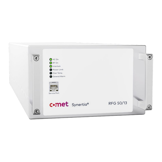
Synertia RF
Comet Synertia RF Manuals
Manuals and User Guides for Comet Synertia RF. We have
1
Comet Synertia RF manual available for free PDF download: User Manual
Comet Synertia RF User Manual (125 pages)
Brand:
Comet
| Category:
Portable Generator
| Size: 4 MB
Table of Contents
Document Information
2
Table of Contents
3
Safety
14
General Safety
14
Scope of this Document
14
Layout Conventions in this Document
15
Abbreviations and Special Terms
16
Table 1: Abbreviations
16
Table 2: Special Terms
16
Scope of the Product
17
Intended Use
17
Improper Use
17
Authorized Users
18
Compliance with Standards and Directives
18
Table 3: SEMI Standards
18
List of Figures
19
Table 4: EU/EN Standards and Directives
19
Hazards
20
High Voltage Hazards
20
List of Tables
21
Radio Frequency Hazards
21
Hot Surface Hazards
22
Heavy Weight Hazards
22
List of Safety Notes
23
Hazard Label Locations
23
Figure 1: Hazard Label on Air-Cooled Generator (Warning Sticker)
23
Figure 2: Hazard Label on Water-Cooled Generator (Warning Sticker)
23
Personal Safety
24
Precautions for Safe Installation and Operation
24
Table 5: Values of External Circuit Breaker
25
Precautions When Performing Troubleshooting, Repair or Maintenance
26
Emergency Procedures
27
Interlock Circuit
28
Figure 3: Interlock Circuit Diagram
28
Figure 4: RF Output Connector with Switch Plate on the Back of Air-Cooled Generator
29
Lockout and Tagout the RF Generator
30
General
30
Shut down Air-Cooled Model
30
Shut down Water-Cooled Model
31
Restart
31
Equipment Safety
32
Responsibility of the Operator
32
Limiting Conditions
32
Table 6: Limiting Conditions
32
Disposal
33
Overview
34
General Information
34
If You Need Help
34
Manufacturer Information
34
Disclaimer and Limitation of Liability
34
Trademarks
35
Customer Feedback
35
Table 7: List of Trademarks Used in this Manual
35
Product Overview
36
Product Description
36
Figure 5: Air-Cooled Synertia® RF Generator
36
Figure 6: Water-Cooled Synertia® RF Generator
36
Components on the Front Panel
37
Figure 7: Front Panel of Air-Cooled Synertia® RF Generator
37
Figure 8: Front Panel of Water-Cooled Synertia® RF Generator
37
Table 8: Components on the Front Panels of Air-Cooled and Water-Cooled Generators
38
Components on the Back Panel
39
Figure 9: Back Panel of Air-Cooled Synertia® RF Generator
39
Table 9: Components on the Back Panel of the Air-Cooled Generator
39
Figure 10: Back Panel of Water-Cooled Synertia® RF Generator
40
Table 10: Components on the Back Panel of the Water-Cooled Generator
40
Figure 11: Interfaces on the Back of Air- and Water-Cooled Synertia® RF Generators
41
Table 11: Interfaces on the Backs of Air- and Water-Cooled Generators - Mainboard
41
Table 12: Interfaces on the Backs of Air- and Water-Cooled Generators - Sync Layer
42
Table 13: Interfaces on the Backs of Air- and Water-Cooled Generators - Fieldbus Layer
42
Control Modes
43
Required Supplies
43
Self-Protection of the Product
43
Theory of Operation
45
Figure 12: Synertia® RF Generator Block Diagram
45
Table 14: Description of Functional Blocks of the Generator
46
Pre-Installation
47
Lifting of the Unit
47
Unpacking the Unit
48
Unit Weight and Center of Mass
48
Packaging
48
Table 15: Center of Mass
48
Unpacking
49
Figure 13: Packaged Air-Cooled and Water-Cooled Generators
49
Lighting
50
Visual Inspection
50
Accessories Shipped with the Product
50
Figure 14: Embedded Air-Cooled and Water-Cooled Generators
50
Mounting
51
Figure 15: Seismic Anchorage Zones Air-Cooled Model
51
Figure 16: Seismic Anchorage Zones Water-Cooled Model
51
Installation and Connection
52
Sequence of Installation
52
Connecting Ground for Equipotential Bonding
53
Figure 17: Ground Connector Air-Cooled Unit
53
Figure 18: Ground Connector Water-Cooled Unit
53
Figure 19: Parts for the Ground Connection
54
Figure 20: Ground Connection Air-Cooled Unit
54
Figure 21: Ground Connection Water-Cooled Unit
54
Connecting RF Generator Interlock to System
55
Figure 22: Rear Interfaces with Focus on Interlock Connectors
55
Connecting Applicable Interfaces
56
CEX Operation
56
Figure 23: Interfaces on the Back of the Generator
56
Figure 24: CEX Initiator-Receiver Configuration
56
ARC-Sync Operation
57
Sync Bus Operation
57
Pulse Operation
58
Connecting RF Power Cable
59
Figure 25: RF out Connector with Non-Depressed Switch Plate (Air- and Water-Cooled Generator)
59
Figure 26: Securely Tightened RF out Connector (Air- and Water-Cooled Generator)
60
Connecting/Disconnecting Cooling Water Connections (Only Water-Cooled Generators)
61
Connecting Cooling Water Connections
61
Figure 27: Water out and Water in Connections in the Lower Right Corner on the Back of the Water-Cooled Generator
61
Figure 28: Fitting with Teflon® Sealing Tape
62
Figure 29 Attachment of Hose
63
Figure 30 Water out and Water in Properly Connected
63
Table 16: Values of Cooling Water
63
Optional: Using a Solenoid Valve
64
Disconnecting Cooling Water Connections
64
Connecting AC Mains
65
Connector Air-Cooled Generators
65
Table 17: Pin-Out Han Q Connector
65
Connector Water-Cooled Generators
66
Table 18: Pin-Out Han C Connector
66
Connection Procedure for Air-Cooled and Water-Cooled Units
67
Figure 31: Wiring of Mains Connector Air-Cooled Unit
67
Figure 32: Wiring of Mains Connector Water-Cooled Unit
67
Figure 33: Mains Connector Air-Cooled Unit
67
Figure 34: Mains Connector Water-Cooled Unit
67
Unit Uninstallation
69
Disposal of Packaging Material
69
Operation
70
Modes of Operation
70
Remote-Control Operation Via the Analog and Digital Signals
70
Remote-Control Operation Via Digital Communications Interface
70
Using the Synertia® RF Generator
71
Commissioning the Synertia® RF Generator
71
Displaying Alarms and Warnings Via Leds
72
Figure 35: Leds on the Front Panel of Air- and Water-Cooled Synertia® RF Generators
72
Table 19: Operating Status
73
Troubleshooting
74
Repair of RF Generators
74
General Instructions
74
Administrative Procedures
74
Authorized Repair Locations
75
Shipment of RMA Units
75
Failure Analysis of Returned Units
75
Claims of Shipping or Handling Damage
76
Repair
76
Troubleshooting Guide
77
General Troubleshooting
77
Checks with the Power off
77
Checks with the Power on
78
Warning and Alarm Messages
79
Difference between Warning and Alarm Messages
79
ID of Warning or Alarm Messages
79
Warranty and Maintenance
80
Warranty Statement and Terms
80
Periodic Checking of the Safety Interlock System
81
Maintenance
81
Calibration
81
Cleaning
82
Mechanical Specifications
83
Spacing and Airflow Requirements
83
Dimensional Drawings
83
Air-Cooled Synertia® RF Generator
84
Figure 36: Front View and Rear View of the Air-Cooled Synertia® RF Generator
84
Figure 37: Left Side View of the Air-Cooled Synertia® RF Generator
84
Figure 38: Top View of the Air-Cooled Synertia® RF Generator
84
Figure 39: Right Side View of the Air-Cooled Synertia® RF Generator
85
Water-Cooled Synertia® RF Generator
86
Figure 40: Front View and Rear View of the Water-Cooled Synertia® RF Generator
86
Figure 41: Left Side View of the Water-Cooled Synertia® RF Generator
86
Figure 42: Top View of the Water-Cooled Synertia® RF Generator
86
Figure 43: Right Side View of the Water-Cooled Synertia® RF Generator
87
Interface Specifications
88
Example of Interface Configuration
88
Figure 44: Interface Configuration
88
User Port - 15-Pin Analog/Digital Interface (Optional)
89
Signals on the 15-Pin Analog/Digital User Port
89
Table 20: 15-Pin User Port - Configuration
91
Table 21: 15-Pin User Port - Signal Specifications
92
Schematics for 15-Pin User Port
93
Figure 45: Analog Input
93
Figure 46: Analog Output
93
Figure 47: Digital Input
93
Figure 48: Digital Output
93
Figure 49: Interlock
94
Figure 50: Serial Interface RS-232
94
CEX Interface
95
DC-Supply Interface
97
Signals on the 5-Pin M8 DC-Supply Connector
97
Figure 51: DC-Supply Connector
97
Table 22: 5-Pin M8 DC-Supply - Configuration
97
Schematics for 5-Pin DC-Supply
98
Interlock Interface
98
Signals on the 3-Pin M8 Interlock Connector
98
Figure 52: Interlock Connector
98
Table 23: DC-Supply
98
Schematics for 3-Pin Interlock
99
Figure 53: Interlock
99
Table 24: 3-Pin M8 Interlock - Configuration
99
Pulse Interface
100
Host Port Communication
101
Host Port Communication Via SHFT Protocol
101
Understanding the SHFT Protocol
101
SHFT Protocol - Request
101
Table 25: Structure of a Request
102
SHFT Protocol - Response
103
Response to a Read Command
103
Table 26: Structure of a Response to a Read Command
103
Response to a Write Command
104
Response to an Invalid Request
104
Table 27: Structure of a Response to an Invalid Request
104
Table 28: Exception Function Codes
105
Table 29: Exception Codes
106
SHFT Protocol - Communication Examples
107
Table 30: Example 1 - Structure of the Request
107
Table 31: Example 1 - Structure of the Response
107
Table 32: Example 2 - Structure of the Request
108
Table 33: Example 2 - Structure of the Response
108
Table 34: Example 3 - Structure of the Request
109
Table 35: Example 3 - Structure of the Response
109
Host Port Communication Via RS-232
110
Default Communication Parameters
110
Data Exchange Via RS-232
110
Table 36: Structure of a Request Via RS-232 with CRC16 Checksum
111
Table 37: Structure of a Response to a Read Command Via RS-232
111
Calculation of the CRC16 Checksum
112
Table 38: Structure of a Response to a Write Command Via RS-232
112
Table 39: Structure of a Response to an Invalid Request Via RS-232
112
Sample Implementation of the CRC16 Checksum
113
Communication Examples
114
Table 40: Example 1 - Write Set-Point - Request
114
Table 41: Example 1 - Write Set-Point - Response
114
Table 42: Example 2 - Read Set-Point - Request
114
Table 43: Example 2 - Read Set-Point - Response
114
Table 44: Example 3 - Write Set-Point - Request
115
Table 45: Example 3 - Write Set-Point - Response
115
Table 46: Example 4 - Read Status - Request
115
Table 47: Example 4 - Read Status - Response
115
List of Parameters
116
Table 48: Colors Used in the Parameter Table
116
Table 49: Parameters
122
Reading Warning and Error Messages
123
Reference Documents
124
Advertisement
Advertisement
Related Products
Comet scout 150 classic
Comet scout 135 classic
Comet K Steel 1001
Comet K Steel 1251
Comet SP 24 SPRAY
Comet SP 50 FOAM
Comet SC 140
Comet Sirius
Comet Blue Series
Comet K STEEL 3.11 TS 11/120 M
Comet Categories
Pressure Washer
Transmitter
Data Loggers
Scrubber
Water Pump
More Comet Manuals
Login
Sign In
OR
Sign in with Facebook
Sign in with Google
Upload manual
Upload from disk
Upload from URL