
Summary of Contents for Comet Synertia RF
- Page 1 Led by experience. Driven by curiosity. User Manual Synertia® RF Generators 15/13 air-cooled 50/13 water-cooled Doc. No. 50075087 000 10...
-
Page 2: Document Information
Offenders will be held liable for the payment of damages. All rights reserved in the event of the grant of a patent, utility model or design. The information contained in this manual is subject to change by Comet Yxlon without prior notice. -
Page 3: Table Of Contents
General ..........................17 1.5.2 Shut down air-cooled model ..................17 1.5.3 Shut down water-cooled model ................. 18 1.5.4 Restart ..........................18 Equipment safety ........................19 The information contained in this manual is subject to change by Comet Yxlon without prior notice. - Page 4 Connecting ground for equipotential bonding .............. 40 Connecting RF generator interlock to system ............... 42 Connecting applicable interfaces ..................43 4.4.1 CEX operation ........................ 43 The information contained in this manual is subject to change by Comet Yxlon without prior notice.
- Page 5 Claims of shipping or handling damage ..............63 6.1.7 Repair ..........................63 Troubleshooting guide ......................64 6.2.1 General troubleshooting ....................64 6.2.2 Checks with the power off ..................64 The information contained in this manual is subject to change by Comet Yxlon without prior notice.
- Page 6 10.1.1 Understanding the SHFT protocol ................88 10.1.2 SHFT protocol – Request .....................88 10.1.3 SHFT protocol – Response ..................90 10.1.4 Response to a read command ................... 90 The information contained in this manual is subject to change by Comet Yxlon without prior notice.
- Page 7 10.2.5 RS-232 – Communication examples ............... 101 10.3 List of parameters ......................103 10.4 Reading warning and error messages ................110 10.5 Reference documents ......................111 The information contained in this manual is subject to change by Comet Yxlon without prior notice.
- Page 8 Figure 27: Water Out and Water In connections in the lower right corner on the back of the water-cooled generator ..................... 48 Figure 28: Fitting with Teflon® sealing tape ................... 49 Figure 29 Attachment of hose......................50 The information contained in this manual is subject to change by Comet Yxlon without prior notice.
- Page 9 Figure 49: Interlock ..........................81 Figure 50: Serial Interface RS-232 ....................81 Figure 51: DC-Supply connector......................84 Figure 52: Interlock connector ......................85 Figure 53: Interlock ..........................86 The information contained in this manual is subject to change by Comet Yxlon without prior notice.
- Page 10 Table 29: Exception Codes ......................... 93 Table 30: Example 1 – Structure of the request ................94 Table 31: Example 1 – Structure of the response ................94 The information contained in this manual is subject to change by Comet Yxlon without prior notice.
- Page 11 Table 47: Example 4 - Read status - response ................102 Table 48: Colors used in the parameter table ................103 Table 49: Parameters ........................109 The information contained in this manual is subject to change by Comet Yxlon without prior notice.
- Page 12 Safety note 29: Information - cables ....................45 Safety note 30: Information - RF cables ..................46 Safety note 31: Warning - RF hazards .................... 46 The information contained in this manual is subject to change by Comet Yxlon without prior notice.
- Page 13 Safety note 42: Danger - high voltage .................... 64 Safety note 43: Warning - electrical shock ..................65 Safety note 44: Warning - cleaning ....................69 The information contained in this manual is subject to change by Comet Yxlon without prior notice.
-
Page 14: Safety
This User Manual is intended for trained and qualified technical personnel who are tasked with installing, operating, servicing and maintaining the Synertia® RF generator. The information contained in this manual is subject to change by Comet Yxlon without prior notice. -
Page 15: Layout Conventions In This Document
INFORMATION Indicates important information for better and safer handling of the device. The colors accord to the ANSI Z535.1-2017. The information contained in this manual is subject to change by Comet Yxlon without prior notice. -
Page 16: Abbreviations And Special Terms
When the interlock chain is open, RF power operation is disabled. Matching network Matching network product providing for optimum adaptation of the load impedance towards the RF generator. Table 2: Special terms The information contained in this manual is subject to change by Comet Yxlon without prior notice. -
Page 17: Scope Of The Product
• use of the product in environments with explosive atmosphere. The above list contains only examples and is not complete. The information contained in this manual is subject to change by Comet Yxlon without prior notice. -
Page 18: Authorized Users
Fire Assessment – included in the SEMI S2 evaluation SEMI S22 Safety Guideline for the Electrical Design of Semiconductor Manufacturing Equipment Table 3: SEMI standards The information contained in this manual is subject to change by Comet Yxlon without prior notice. -
Page 19: List Of Figures
Table 4: EU/EN standards and directives INFORMATION For more information, refer to the CE-Declaration of Conformity supplied in the shipping container. Safety note 2: Information – CE-Declaration The information contained in this manual is subject to change by Comet Yxlon without prior notice. -
Page 20: Hazards
Only water-cooled generator: If any fluid leaks are seen, shut off power and do not attempt to handle electrical connectors on the unit while water is present. The information contained in this manual is subject to change by Comet Yxlon without prior notice. -
Page 21: List Of Tables
The RF cable must be properly connected on both ends. • The RF cable shielding must be grounded on both ends (generator and load side). • Take appropriate precautions against electrostatic discharge. The information contained in this manual is subject to change by Comet Yxlon without prior notice. -
Page 22: Hot Surface Hazards
193 cm / 76 in. See also section 3.1 "Lifting of the unit" on page 34. The information contained in this manual is subject to change by Comet Yxlon without prior notice. -
Page 23: List Of Safety Notes
The hazard labels shown here is attached to the top of the Synertia® RF generators. Figure 1: Hazard label on air-cooled generator (warning sticker) Figure 2: Hazard label on water-cooled generator (warning sticker) The information contained in this manual is subject to change by Comet Yxlon without prior notice. -
Page 24: Personal Safety
Occasionally, condensation may create temporary conductivity when the device is not operating. However, the device must not be operated wet. The information contained in this manual is subject to change by Comet Yxlon without prior notice. -
Page 25: Table 5: Values Of External Circuit Breaker
Failure to comply may result in serious injury or death to the user and may be a serious breach of local regulations. Safety note 8: Warning - safe installation The information contained in this manual is subject to change by Comet Yxlon without prior notice. -
Page 26: Precautions When Performing Troubleshooting, Repair Or Maintenance
• Prior to cleaning, switch off the mains supply. Use a mild cleaning agent with a moist cloth for cleaning. Never clean dripping wet. The information contained in this manual is subject to change by Comet Yxlon without prior notice. -
Page 27: Emergency Procedures
In an emergency, immediately perform the following actions in the sequence given: Turn-off the external circuit breaker feeding the generator. Extinguish fires with a suitable extinguishing medium – never use water! The information contained in this manual is subject to change by Comet Yxlon without prior notice. -
Page 28: Interlock Circuit
Internal 24 V DC source, 0.1 A fuse • Interlock Connector Two specific pins of this connector must be connected to each other externally to enable RF power operation. The information contained in this manual is subject to change by Comet Yxlon without prior notice. -
Page 29: Figure 4: Rf Output Connector With Switch Plate On The Back Of Air-Cooled Generator
RF Driver by connecting the gate bias voltage node to ground • disabling the DC output of the AC/DC Power Converter supplying the RF Driver and the RF Power Amplifier The information contained in this manual is subject to change by Comet Yxlon without prior notice. -
Page 30: Lockout And Tagout The Rf Generator
This may entail placing a lockable plastic "boot" over the power cable after removal. The information contained in this manual is subject to change by Comet Yxlon without prior notice. -
Page 31: Shut Down Water-Cooled Model
This is the reverse of above steps. Double-check the front or back panel lights after power-up to be sure power-up was successful. Never attempt to lock the unit in the "ON" position. The information contained in this manual is subject to change by Comet Yxlon without prior notice. -
Page 32: Equipment Safety
The minimum RF output duration is identical to the minimum external pulse duration. This will result in a warning. Table 6: Limiting conditions The information contained in this manual is subject to change by Comet Yxlon without prior notice. -
Page 33: Disposal
Please contact Comet Yxlon technical support or customer support to request a quote for the disposal of Comet Yxlon product. Upon request, a certificate of disposal can be issued to confirm that a unit has been scrapped. The information contained in this manual is subject to change by Comet Yxlon without prior notice. -
Page 34: Overview
The documentation has been prepared with care. The technology described is, however, constantly under development. For that reason, the documentation is not in every case checked for consistency with performance data, standards or other characteristics. The information contained in this manual is subject to change by Comet Yxlon without prior notice. -
Page 35: Trademarks
Please send any comments on the content, organization, or format of this user manual to: • pct@comet.tech To order a manual, please contact Technical Support: • technical.support.pct.de@comet.tech The information contained in this manual is subject to change by Comet Yxlon without prior notice. -
Page 36: Product Overview
This RF generator employs latest technology in a compact 19 in half rack design. Figure 5: Air-cooled Synertia® RF generator Figure 6: Water-cooled Synertia® RF generator The information contained in this manual is subject to change by Comet Yxlon without prior notice. -
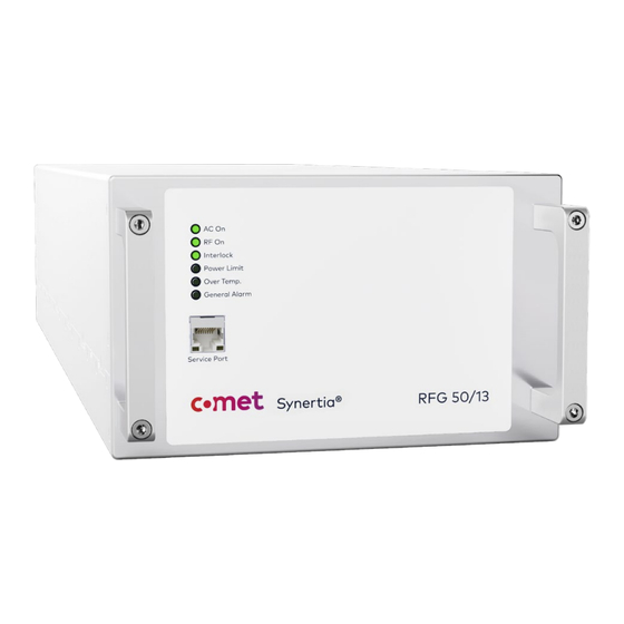
Page 37: Components On The Front Panel
2.2.2 Components on the front panel Figure 7: Front panel of air-cooled Synertia® RF generator Figure 8: Front panel of water-cooled Synertia® RF generator The information contained in this manual is subject to change by Comet Yxlon without prior notice. -
Page 38: Table 8: Components On The Front Panels Of Air-Cooled And Water-Cooled Generators
Do not use the front panel handles for lifting or carrying the generator. Table 8: Components on the front panels of air-cooled and water-cooled generators The information contained in this manual is subject to change by Comet Yxlon without prior notice. -
Page 39: Components On The Back Panel
Mains connector for connecting the 1-phase mains voltage Harting™ Han cable Modular coupling Table 9: Components on the back panel of the air-cooled generator The information contained in this manual is subject to change by Comet Yxlon without prior notice. -
Page 40: Figure 10: Back Panel Of Water-Cooled Synertia® Rf Generator
NPT 3/8 screw- Note: May differ from image depending on configuration! in nipples Table 10: Components on the back panel of the water-cooled generator The information contained in this manual is subject to change by Comet Yxlon without prior notice. -
Page 41: Figure 11: Interfaces On The Back Of Air- And Water-Cooled Synertia® Rf Generators
Note: Not yet in use! Table 11: Interfaces on the backs of air- and water-cooled generators – Mainboard The information contained in this manual is subject to change by Comet Yxlon without prior notice. -
Page 42: Table 12: Interfaces On The Backs Of Air- And Water-Cooled Generators - Sync Layer
For connecting the Synertia® RF generator to an 2 x RJ45 Optional In/Out existing EtherCAT® system fieldbus Table 13: Interfaces on the backs of air- and water-cooled generators – Fieldbus Layer The information contained in this manual is subject to change by Comet Yxlon without prior notice. -
Page 43: Control Modes
Signal voltage on interfaces too low or too high (e. g. CEX input) • Frequency of external pulse signal out of specification • Frequency of external CEX signal out of specification The information contained in this manual is subject to change by Comet Yxlon without prior notice. - Page 44 Excessive reflected power not in control of the generator (e. g. when RF power is applied to the RF output by an external source) The information contained in this manual is subject to change by Comet Yxlon without prior notice.
-
Page 45: Theory Of Operation
2.3 Theory of operation The Synertia® RF generator includes functional blocks as shown in the following block diagram: Figure 12: Synertia® RF generator block diagram The information contained in this manual is subject to change by Comet Yxlon without prior notice. -
Page 46: Table 14: Description Of Functional Blocks Of The Generator
Converts DC from AC/DC converter to corresponding RF power RF output 50 Ω coaxial RF output Table 14: Description of functional blocks of the generator The information contained in this manual is subject to change by Comet Yxlon without prior notice. -
Page 47: Pre-Installation
Fans on the unit, if present, must not be blocked. The information contained in this manual is subject to change by Comet Yxlon without prior notice. -
Page 48: Unpacking The Unit
It is the operator's responsibility to acclimate the device appropriately before unpacking it and to operate it only within the approved environmental conditions. Safety note 19: Notice - humidity The information contained in this manual is subject to change by Comet Yxlon without prior notice. -
Page 49: Unpacking
Please retain the custom packaging if a return shipment should be needed in the future. Figure 13: Packaged air-cooled and water-cooled generators The product is embedded in form fitted foam. The information contained in this manual is subject to change by Comet Yxlon without prior notice. -
Page 50: Lighting
If any of these items should be missing upon receipt, or if they cannot be found for other reasons, please contact customer support for a replacement. The information contained in this manual is subject to change by Comet Yxlon without prior notice. -
Page 51: Mounting
Seismic Tie Down Seismic Tie Down Figure 15: Seismic anchorage zones air-cooled model Seismic Tie Down Seismic Tie Down Figure 16: Seismic anchorage zones water-cooled model The information contained in this manual is subject to change by Comet Yxlon without prior notice. -
Page 52: Installation And Connection
Connect cooling water source and drain (only water-cooled generators). For details see 4.6 "Connecting/disconnecting cooling water connections (only water-cooled generators)". Connect AC mains. For details, see 4.7 "Connecting AC mains". The information contained in this manual is subject to change by Comet Yxlon without prior notice. -
Page 53: Connecting Ground For Equipotential Bonding
Safety note 24: Warning - grounding Figure 17: Ground connector air-cooled unit Figure 18: Ground connector water-cooled unit The information contained in this manual is subject to change by Comet Yxlon without prior notice. -
Page 54: Figure 19: Parts For The Ground Connection
Use a grounding cable with an adequate cross-section in accordance with local rules and regulations. Figure 20: Ground connection air-cooled unit Figure 21: Ground connection water-cooled unit The information contained in this manual is subject to change by Comet Yxlon without prior notice. -
Page 55: Connecting Rf Generator Interlock To System
Defeating the interlock function can result in dangerous situations if the generator is allowed to supply power into the customer's system with inadequate safety precautions. Safety note 25: Warning - interlock The information contained in this manual is subject to change by Comet Yxlon without prior notice. -
Page 56: Connecting Applicable Interfaces
(see the example in Figure 24) using suitable high-quality, double-shielded coaxial cables. Make sure that the connections between cables and connectors are tight. The information contained in this manual is subject to change by Comet Yxlon without prior notice. -
Page 57: Arc-Sync Operation
Note: Since the Sync Bus feature is not yet implemented in the current firmware version, leave this interface unconnected. Safety note 28: Information - Sync Bus The information contained in this manual is subject to change by Comet Yxlon without prior notice. -
Page 58: Pulse Operation
Make sure that the connections between cables and connectors are tight. INFORMATION Note: The cables are not provided by Comet. Safety note 29: Information - cables The information contained in this manual is subject to change by Comet Yxlon without prior notice. -
Page 59: Connecting Rf Power Cable
Recommended torque: 0.7 Nm to 1.1 Nm Safety note 32: Notice - connectors Spring-loaded switch plate Figure 25: RF Out connector with non-depressed switch plate (air- and water-cooled generator) The information contained in this manual is subject to change by Comet Yxlon without prior notice. -
Page 60: Figure 26: Securely Tightened Rf Out Connector (Air- And Water-Cooled Generator)
Figure 26: Securely tightened RF Out connector (air- and water-cooled generator) Make sure that the RF cable is connected also on the plasma-system side. Make sure that the cable is grounded on both ends. The information contained in this manual is subject to change by Comet Yxlon without prior notice. -
Page 61: Connecting/Disconnecting Cooling Water Connections (Only Water-Cooled Generators)
To connect the cooling water connections, proceed as follows: Figure 27: Water Out and Water In connections in the lower right corner on the back of the water-cooled generator The information contained in this manual is subject to change by Comet Yxlon without prior notice. -
Page 62: Figure 28: Fitting With Teflon® Sealing Tape
(two to three turns). NOTICE To avoid damages to the fittings, the maximum tightening torque is 30 Nm. Safety note 36: Notice - tightening torque The information contained in this manual is subject to change by Comet Yxlon without prior notice. -
Page 63: Figure 29 Attachment Of Hose
(see previous step). Check again for leaks after approx. 1 hour after commissioning of the cooling circuit (recommended). The information contained in this manual is subject to change by Comet Yxlon without prior notice. -
Page 64: Optional: Using A Solenoid Valve
Teflon® tape. NOTICE Make sure that no Teflon® tape residues get inside the cooling lines of the generator. Safety note 38: Notice - Teflon tape The information contained in this manual is subject to change by Comet Yxlon without prior notice. -
Page 65: Connecting Ac Mains
1 pc. Han Q 2/0-f 1.5-2,5 mm² / 16-14 AWG (P/N: 09 12 002 2755) Signal Phase Neutral Protective Earth Table 17: Pin-out Han Q connector The information contained in this manual is subject to change by Comet Yxlon without prior notice. -
Page 66: Connector Water-Cooled Generators
1 pc. Han CGM-M M25x1,5 D.13-18 mm (P/N: 19 00 000 5092) Signal Phase 1 Phase 2 Phase 3 Housing Protective Earth Table 18: Pin-out Han C connector The information contained in this manual is subject to change by Comet Yxlon without prior notice. -
Page 67: Connection Procedure For Air-Cooled And Water-Cooled Units
If required by local electrical regulations, install an external disconnect device in the generator power supply chain to disconnect all current-carrying conductors in shutdown mode. The information contained in this manual is subject to change by Comet Yxlon without prior notice. - Page 68 WARNING To prevent potential life-threatening danger, a switch or circuit breaker must not interrupt the protective conductor. Safety note 39: Warning - protective conductor The information contained in this manual is subject to change by Comet Yxlon without prior notice.
-
Page 69: Unit Uninstallation
Comet Yxlon GmbH for service, repair, or disposal. If the package shall be disposed of, observe all local regulations regarding separation and disposal of the individual materials. The information contained in this manual is subject to change by Comet Yxlon without prior notice. -
Page 70: Operation
For detailed information on the available commands, please refer to chapter 10 "Host port communication" on page 88. The information contained in this manual is subject to change by Comet Yxlon without prior notice. -
Page 71: Using The Synertia® Rf Generator
See sections 0 “List of parameters” and 10.4 “Reading warning and error messages”. When configuration is done, the settings are stored in the unit and recalled the next time the unit is switched on. The information contained in this manual is subject to change by Comet Yxlon without prior notice. -
Page 72: Displaying Alarms And Warnings Via Leds
(Over Temp. LED), • any error occurs during the operation of the device (General Alarm LED). The information contained in this manual is subject to change by Comet Yxlon without prior notice. -
Page 73: Table 19: Operating Status
Detailed error information can be retrieved via the communication interface by using the corresponding commands (see section 10.3 "List of parameters" on page 102and section 10.4 “ Reading warning and error messages” on page 110). The information contained in this manual is subject to change by Comet Yxlon without prior notice. -
Page 74: Troubleshooting
The generators are not user serviceable. 6.1.1 General Instructions Synertia® RF generators can be sent back to Comet Yxlon for repair if they are found to have malfunctions. Before returning any product for repair and/or adjustment, first follow all troubleshooting procedures. -
Page 75: Authorized Repair Locations
No third parties are authorized to repair Comet Yxlon products. Any attempt, by any third party, to repair a Comet Yxlon product will immediately void the warranty. Upon receipt of an RMA number request, Comet Yxlon will assign the repair site to which a defective or malfunctioning unit must be returned. -
Page 76: Claims Of Shipping Or Handling Damage
Warranty repairs typically are completed in a two-to-three-week cycle-time. Customer approval and a purchase order for the quoted repair price are required prior to the commencement of any non-warranty work. The information contained in this manual is subject to change by Comet Yxlon without prior notice. -
Page 77: Troubleshooting Guide
Check to determine whether any system-related circuit breaker has been tripped. Verify that the input power to the unit meets specifications. Ensure ground connections are adequate and secure. The information contained in this manual is subject to change by Comet Yxlon without prior notice. -
Page 78: Checks With The Power On
Check the unit’s input and remote power connections to ensure the proper power is being supplied to the unit. Check the front panel display for errors (see section 6.3 “Warning and alarm messages”). The information contained in this manual is subject to change by Comet Yxlon without prior notice. -
Page 79: Warning And Alarm Messages
In some cases, however, software warning and alarm messages can also be caused by defective hardware. In this unlikely event, note the number of the warning or alarm message and contact technical support. The information contained in this manual is subject to change by Comet Yxlon without prior notice. -
Page 80: Warranty And Maintenance
Comet Yxlon's determination with regard thereto shall be final. The Comet Yxlon warranty statement may be superseded by a service agreement entered between Comet Yxlon and the customer. The information contained in this manual is subject to change by Comet Yxlon without prior notice. -
Page 81: Periodic Checking Of The Safety Interlock System
The specified power measurement accuracy is only valid if the generator is within a calibration period of 12 months. Please contact support or your local dealer for (re-)calibration. The information contained in this manual is subject to change by Comet Yxlon without prior notice. -
Page 82: Cleaning
Safety note 44: Warning - cleaning Use a mild cleaning agent with a moist cloth for cleaning. Never clean dripping wet! See also section 1.4.2. The information contained in this manual is subject to change by Comet Yxlon without prior notice. -
Page 83: Mechanical Specifications
Synertia® RF generator. The anchorage locations are shown in Figure 37, Figure 39, Figure 41 and Figure 43. Information on fixation screws is provided as well. The information contained in this manual is subject to change by Comet Yxlon without prior notice. -
Page 84: Air-Cooled Synertia® Rf Generator
Figure 36: Front view and rear view of the air-cooled Synertia® RF generator Figure 37: Left side view of the air-cooled Synertia® RF generator Figure 38: Top view of the air-cooled Synertia® RF generator The information contained in this manual is subject to change by Comet Yxlon without prior notice. -
Page 85: Figure 39: Right Side View Of The Air-Cooled Synertia® Rf Generator
User Manual Synertia® RF Generator Figure 39: Right side view of the air-cooled Synertia® RF generator The information contained in this manual is subject to change by Comet Yxlon without prior notice. -
Page 86: Water-Cooled Synertia® Rf Generator
Figure 40: Front view and rear view of the water-cooled Synertia® RF generator Figure 41: Left side view of the water-cooled Synertia® RF generator Figure 42: Top view of the water-cooled Synertia® RF generator The information contained in this manual is subject to change by Comet Yxlon without prior notice. -
Page 87: Figure 43: Right Side View Of The Water-Cooled Synertia® Rf Generator
User Manual Synertia® RF Generator Figure 43: Right side view of the water-cooled Synertia® RF generator The information contained in this manual is subject to change by Comet Yxlon without prior notice. -
Page 88: Interface Specifications
The figure below shows an example of an interface configuration of the Synertia® RF generator. Table 20 on page 76 shows the main functions and properties of the interfaces. Figure 44: Interface configuration The information contained in this manual is subject to change by Comet Yxlon without prior notice. -
Page 89: User Port - 15-Pin Analog/Digital Interface (Optional)
Global Error State When the generator is ready to deliver RF power, a 5 V signal is sent to this output. The information contained in this manual is subject to change by Comet Yxlon without prior notice. - Page 90 Analog Out Return Return For operation, this return must be grounded either on host or client side. Overtemperature An error on this digital output indicates overtemperature. The information contained in this manual is subject to change by Comet Yxlon without prior notice.
-
Page 91: Table 20: 15-Pin User Port - Configuration
The digital outputs are floating and referenced to the Isolated GND (Pin 4). The reference pin must be grounded either on host or client side. The information contained in this manual is subject to change by Comet Yxlon without prior notice. -
Page 92: Table 21: 15-Pin User Port - Signal Specifications
Each signal like digital and analog in- and outputs uses a return signal as reference. For operation, all returns must be grounded either on host or client side. Table 21: 15-pin User Port – Signal specifications The information contained in this manual is subject to change by Comet Yxlon without prior notice. -
Page 93: Schematics For 15-Pin User Port
User Manual Synertia® RF Generator 9.2.2 Schematics for 15-pin User Port Figure 45: Analog Input Figure 46: Analog Output Figure 47: Digital Input Figure 48: Digital Output The information contained in this manual is subject to change by Comet Yxlon without prior notice. -
Page 94: Figure 49: Interlock
User Manual Synertia® RF Generator Figure 49: Interlock Figure 50: Serial Interface RS-232 The information contained in this manual is subject to change by Comet Yxlon without prior notice. -
Page 95: Cex Interface
Phase offsets of the RF and CEX output signals are related to CEX input signal. If the output frequency of the CEX or RF signal is different from the input signal, phase offset values are irrelevant. The information contained in this manual is subject to change by Comet Yxlon without prior notice. - Page 96 50 Ω terminator. For the technical data of the CEX signals (e. g. input/output level, tolerance or frequency range), refer to the data sheet. The information contained in this manual is subject to change by Comet Yxlon without prior notice.
-
Page 97: Dc-Supply Interface
The solenoid is switched off when the generator is not dissipating heat to prevent condensation inside the generator. Table 22: 5-pin M8 DC-Supply – Configuration The information contained in this manual is subject to change by Comet Yxlon without prior notice. -
Page 98: Schematics For 5-Pin Dc-Supply
The 24 V provided at this output is the supply voltage for the external interlock chain. The output is protected by a self-resetting 100 mA fuse. The information contained in this manual is subject to change by Comet Yxlon without prior notice. -
Page 99: Schematics For 3-Pin Interlock
20 … 24 V referenced to GND has to be provided at this pin. Not connected Table 24: 3-pin M8 Interlock – Configuration 9.5.2 Schematics for 3-pin Interlock Figure 53: Interlock The information contained in this manual is subject to change by Comet Yxlon without prior notice. -
Page 100: Pulse Interface
For the technical data of the pulse signals (e. g. pulse frequency, duty cycle range, time resolution or rise and fall times), refer to the data sheet. The information contained in this manual is subject to change by Comet Yxlon without prior notice. -
Page 101: Host Port Communication
Depending on the amount of transferred data, the request can have a length between 5 and 253 bytes. It consists of header, command number and data. The following table shows the structure of the request. The information contained in this manual is subject to change by Comet Yxlon without prior notice. -
Page 102: Table 25: Structure Of A Request
Read commands (FC = 0x41) always contain 2 bytes of data with the fixed values 0x00 and 0x01. The information contained in this manual is subject to change by Comet Yxlon without prior notice. -
Page 103: Shft Protocol - Response
The number and type of data bytes sent in the response of the generator depends on the requested command or parameter number. For details, see 10.3 „ List of parameters“ on page 102. The information contained in this manual is subject to change by Comet Yxlon without prior notice. -
Page 104: Response To A Write Command
1. For an invalid read command, the exception function code is 0xC1 (0x41 + 0x80), for an invalid write command it is 0xC2 (0x42 + 0x80). The information contained in this manual is subject to change by Comet Yxlon without prior notice. -
Page 105: Table 28: Exception Function Codes
The parameter is not changeable while RF is on. Turn RF off and send the parameter again. 0x88 Not Allowed Writing this parameter is not allowed (insufficient rights). The information contained in this manual is subject to change by Comet Yxlon without prior notice. -
Page 106: Table 29: Exception Codes
0x8B Value Too High The sent value is too high. 0x8C Value Too Low The sent value is too low. Table 29: Exception Codes The information contained in this manual is subject to change by Comet Yxlon without prior notice. -
Page 107: Shft Protocol - Communication Examples
(4-byte integer value 0x00000001 = 1) Example 0x0A 0x41 0x04 0x00 0x00 0x00 0x01 Value Table 31: Example 1 – Structure of the response The information contained in this manual is subject to change by Comet Yxlon without prior notice. -
Page 108: Table 32: Example 2 - Structure Of The Request
(4-byte integer value 0x00000000 = 0 W) bytes) Example 0x0A 0x41 0x04 0x00 0x00 0x00 0x00 Value Table 33: Example 2 – Structure of the response The information contained in this manual is subject to change by Comet Yxlon without prior notice. -
Page 109: Table 34: Example 3 - Structure Of The Request
(0x00000001= ‘1’ for ‘RF on’) = read) Example 0x0A 0x42 0x03 0xE9 0x00 0x00 0x00 0x01 Value Table 35: Example 3 – Structure of the response The information contained in this manual is subject to change by Comet Yxlon without prior notice. -
Page 110: Host Port Communication Via Rs-232
Example: This is only valid for baud rates up to 19200 bits/s. Above this, a fixed detection pause time of 1750 µs is used. The information contained in this manual is subject to change by Comet Yxlon without prior notice. -
Page 111: Table 36: Structure Of A Request Via Rs-232 With Crc16 Checksum
Calculated over bytes (fixed) (fixed) trailing (max. 249) number 1 to n data bytes Table 37: Structure of a response to a read command via RS-232 The information contained in this manual is subject to change by Comet Yxlon without prior notice. -
Page 112: Calculation Of The Crc16 Checksum
CRC-16-ANSI standard with reversed representation (0xA001) of the polynomial. For more details, see: https://en.wikipedia.org/wiki/Cyclic_redundancy_check. The checksum is calculated over the whole message packet (request or response), excluding the CRC16 itself. The information contained in this manual is subject to change by Comet Yxlon without prior notice. -
Page 113: Sample Implementation Of The Crc16 Checksum
///< Number of bytes in array unsigned short count; count count < bytes; count++) unsigned char char)(crc ^((const unsigned char*)data)[count]); (unsigned short)((crc (unsigned >> 8) ^ Crc16tab[tmp]); return crc; The information contained in this manual is subject to change by Comet Yxlon without prior notice. -
Page 114: Communication Examples
Table 42: Example 2 - Read set-point – request Address Function Code Length Data 0x0A 0x41 0x04 0x00 0x03 0x0D 0x40 0xA1 0xB1 Table 43: Example 2 - Read set-point – response The information contained in this manual is subject to change by Comet Yxlon without prior notice. -
Page 115: Table 44: Example 3 - Write Set-Point - Request
Table 46: Example 4 - Read status - request Address Function Code Length Data 0x0ARX 0x41 0x04 0x00 0x00 0x00 0x01 0x95 0x11 Table 47: Example 4 - Read status - response The information contained in this manual is subject to change by Comet Yxlon without prior notice. -
Page 116: List Of Parameters
Current time from internal buffered real time clock (format: hh:mm:ss) 7102 Date "2021-03-25" string Current date from internal buffered real time clock (format: yyyy-mm-dd) The information contained in this manual is subject to change by Comet Yxlon without prior notice. - Page 117 The load power (load power = forward power - reflected power) is controlled by the set point for the internal power control (see parameter 1206 “Power set point”). The information contained in this manual is subject to change by Comet Yxlon without prior notice.
- Page 118 “Pulse mode internal 1” The pulse is generated internally. “Pulse mode external inverted” The pulse is generated by an inverted external source. The information contained in this manual is subject to change by Comet Yxlon without prior notice.
- Page 119 The current RF voltage in mV can be retrieved from the unit. 8025 RF current int (32 bit) The current RF current in mA can be retrieved from the unit. The information contained in this manual is subject to change by Comet Yxlon without prior notice.
- Page 120 Error 5 int (32 bit) 8110 Error 5 state int (32 bit) 8138 Error 6 int (32 bit) 8112 Error 6 state int (32 bit) The information contained in this manual is subject to change by Comet Yxlon without prior notice.
- Page 121 Error 14 state int (32 bit) 8147 Error 15 int (32 bit) 8130 Error 15 state int (32 bit) 8148 Error 16 int (32 bit) The information contained in this manual is subject to change by Comet Yxlon without prior notice.
-
Page 122: Table 49: Parameters
(32 bit) 8180 Warning 14 int (32 bit) 8181 Warning 15 int (32 bit) 8182 Warning 16 int (32 bit) Table 49: Parameters The information contained in this manual is subject to change by Comet Yxlon without prior notice. -
Page 123: Reading Warning And Error Messages
1001 “Command” with value 9: "Reset Errors”. The state of each error can be read using the parameters 8102, 8104, … 8132. The information contained in this manual is subject to change by Comet Yxlon without prior notice. -
Page 124: Reference Documents
[1] Data sheet Air-Cooled Synertia® RF generator [2] Data sheet Water-Cooled Synertia® RF generator [3] CE-Declaration of Conformity Air-cooled Synertia® RF generator [4] CE-Declaration of Conformity Water-cooled Synertia® RF generator The information contained in this manual is subject to change by Comet Yxlon without prior notice. - Page 125 Taman Perindustrian Batu Kawan T +1 408 325 8770 14110 Bandar Cassia Penang China Taiwan Comet Mechanical Equipment (Shanghai) Co. Ltd. Comet Solutions Taiwan Ltd. 2777 East Jinxiu Road, Building 36, 8th floor 1F., No. 120, Guangming Road Pudong, Shanghai 201206 Qionglin Township...
Need help?
Do you have a question about the Synertia RF and is the answer not in the manual?
Questions and answers