Sign In
Upload
Manuals
Brands
COBHAM Manuals
Antenna
Sea Tel 4010W-17
COBHAM Sea Tel 4010W-17 Manuals
Manuals and User Guides for COBHAM Sea Tel 4010W-17. We have
1
COBHAM Sea Tel 4010W-17 manual available for free PDF download: Installation Manual
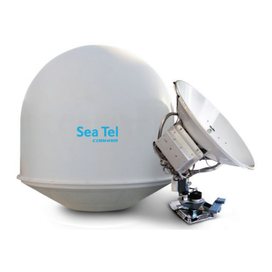
COBHAM Sea Tel 4010W-17 Installation Manual (141 pages)
TRANSMIT / RECEIVE SYSTEM WITH SELECTABLE CO-POL OR CROSS-POL RECEIVE, BROADBAND-AT-SEA
Brand:
COBHAM
| Category:
Antenna
| Size: 13 MB
Table of Contents
Table of Contents
5
1 Series System Configuration(S)
11
Basic System Information
11
System Cables
11
Other Inputs to the Eries System
11
Dual Antenna Configuration
12
Dual Antenna Arbitrator
13
Open Antenna-Modem Interface Protocol (Openamip™) Specification
13
Overview
13
Interface Requirements
14
Utilized Openamip Commands
14
2 Site Survey
15
Site Selection Aboard Ship
15
Antenna Shadowing (Blockage) and RF Interference
15
Mounting Foundation
16
Mounting on Deck or Deckhouse
16
ADE Mounting Considerations
16
Sizing of the Support Pedestal
16
Mounting Height
17
Mast Configurations
17
Vertical Masts
18
Raked Masts
18
Girder Masts
18
Truss Mast
19
Safe Access to the Ade
19
Below Decks Equipment Location
19
Cables
19
ADE/BDE Coaxial Cables
20
Antenna Power Cable
20
Air Conditioner Power Cable
20
ACU Power Cable/Outlet
20
Gyro Compass Cable
20
Grounding
20
3 Installation
21
Unpacking and Inspection
21
Assembly Notes and Warnings
21
Installing the Ade
22
Prepare the 50", 60", 66" or 76" Radome Assembly
22
Installing the 50, 60 or 66" Radome Assembly
23
Removing the Shipping/Stow Restraints PRIOR to Power-Up
26
Removing the AZ Shipping/Stow Restraint
26
Removing the el Shipping/Stow Restraint
27
Removing the CL Shipping/Stow Restraint
28
Cable Installation
29
Shipboard Cable Installation
29
Installing the below Decks Equipment
29
General Cautions & Warnings
29
Preparing BDE Location
29
System Configuration
30
Installing the below Deck Equipment
30
Connecting the below Decks Equipment
30
Connecting the ADE AC Power Cable
30
Connecting the BDE AC Power Cables
30
Connecting the ADE if Coaxes
31
Connect the Modem TXIF Coax
31
Antenna Control Unit Connections
31
Radio Control Serial Cable
31
Terminal Mounting Strip (TMS) Connections
31
Other BDE Connections
34
Final Checks
34
Visual/Electrical Inspection
34
Electrical - Double Check Wiring Connections
34
Power-Up
34
Antenna Maintenance
35
Balancing the Antenna
35
Fine Balance and Monitoring Motor Drive Torque
35
4 Basic Setup of the Acu
39
Operator Settings
39
Setup Parameter Display and Entry Menus
39
Default Setup Parameters for Your Antenna
39
Save New Parameters
40
5 Setup - Ships Gyro Compass
41
Gyro Type
41
Updating the Gyro Type Parameter
41
Compass
41
6 Setup - Tracking Receiver - Vsat
43
Determining the if Tracking Frequency (Mhz)
43
Khz
43
Fec
43
L-Band SCPC Receiver
43
Tone
43
VSAT Application
43
Volt
44
Sat Skew
44
Nid
44
7 Setup - Band Selection
45
8 Setup - Targeting
49
Auto Trim
49
Manually Optimizing Targeting
49
El Trim
50
Az Trim
50
9 Setup - Home Flag Offset
51
Electronic Calibration of Relative Antenna Position (Home Flag Offset)
51
You Found a Large AZ TRIM Value
51
You Observe "Home" Pointing Is LEFT of the Bow-Line
52
You Observe "Home" Pointing Is RIGHT of the Bow-Line
52
To Enter the HFO Value in the DAC_2202
53
Mechanical Calibration of Relative Antenna Position (Home Flag Offset)
54
10 Setup - Searching
55
Searching Operation
55
Default Standard (Box) Search Pattern
55
Inclined Orbit Search Pattern
56
No Gyro Search Pattern
57
Changing the Search Parameters
58
Auto Thres
58
El Step Size
58
Az Step Size
58
Step Integral
58
Search Inc
59
Search Limit
59
Search Delay
59
Sweep Inc
59
Save New Parameters
59
11 Setup - Blockage & Rf Radiation Hazard Zones
61
Radiation Hazard and Blockage Mapping (AZ LIMIT Parameters)
61
Save New Parameters
64
12 Setup - Modem Connections, Setup and Test
65
Idirect Modems
65
Comtech Modems
65
Hughes Modems
65
Connections (ACU to Satellite Modem)
66
Idirect Modems
66
Comtech Modems
66
Hughes Modems
66
System Type Parameter
66
Blockage Simulation Test
67
Nput in the Acu
68
Save New Parameters
69
13 Setup - Optimizing Polarity & Cross-Pol Isolation
71
Sat Skew Setting
71
Polarity Angle (Polang) Parameters
71
Optimizing Auto-Polarization on Receive Signal
71
Optimizing Auto-Polarization Cross-Pol Isolation
72
14 Setup - Other Parameters
73
Setup Parameter Display and Entry Menus
73
OFFSET (May Not be in Your Software)
73
SCALE (May Not be in Your Software)
73
Remote Command
73
Remote Monitor
73
To Disable/Enable Dishscan
73
Satellite Reference Mode
74
Remote Parameters
74
15 Functional Testing
75
Acu / Antenna System Check
75
Latitude/Longitude Auto-Update Check
75
Heading Following
75
Blockage Simulation Test
75
Four Quadrant Test Tracking
76
Blockage Simulation Test
77
16 Installation Troubleshooting
79
17 Stowing the Antenna for Underway with Power off
83
Installing the Stow Restraints
83
Installing the AZ Shipping/Stow Restraint
83
Installing the el Shipping/Stow Restraint
84
Installing the CL Shipping/Stow Restraint
85
Removing the Shipping/Stow Restraints PRIOR to Power-Up
86
Removing the AZ Shipping/Stow Restraint
86
Removing the el Shipping/Stow Restraint
87
Removing the CL Shipping/Stow Restraint
88
18 Dac-2202 Technical Specifications
89
Dac-2202 Antenna Control Unit
89
General
89
Front Panel
89
Rear Panel
89
J4A "Antenna" Pedestal M&C Interface
89
J4B "Antenna" Pedestal M&C Interface
90
J3 "M&C" Aux Serial Interface
90
J2 "NMEA A" Interface
90
J2 "NMEA B" Interface
90
Ethernet
90
DVB Compliant Tracking Receiver
91
L-Band SCPC Narrow Band Tracking Receiver
91
Narrow Band SCPC Receiver (DAC-2302 ONLY)
91
Terminal Mounting Strip
91
Synchro Interface
91
SBS Interface
92
Control Interface
92
NMEA Interface
92
Environmental Conditions
93
Dac-2202 Ac Power Consumption
93
Cables
93
IF Signal Cables
93
Sbs/Synchro Gyro Compass Interface Cable (Customer Furnished)
93
17 Technical Specifications
95
Antenna Reflector/Feed 4010
95
Smw Quad Band Lnb
95
TX Radio Package ( -17 Systems)
96
Buc Power Supply
96
Mk 2 Pedestal Control Unit (Pcu)
96
Mh Z Base & Pedestal Unlimited Azimuth Modems (3 Channel )
97
Mk 2 Motor Driver Enclosure (Mde)
97
Stabilized Antenna Pedestal Assembly
98
Radome Assembly , 50
99
Radome Assembly , 60
99
Xx10 Environmental Specifications
100
Climatic Conditions
100
Chemically Active Substances
100
Mechanical Conditions
100
Transit Conditions
100
Below Decks Equipment
100
Antenna Control Unit (ACU)
100
Terminal Mounting Strip (TMS)
100
Satellite Modem
100
Router
100
Cables
101
Antenna Control Cable (Provided from ACU to the Base MUX)
101
Antenna L-Band if Coax Cables (Customer Furnished)
101
Multi-Conductor Cables (Customer Furnished)
101
20 Drawings
103
Dac-2202 Antenna Control Unit Drawings
103
4010W-17 Ku-Band Model Specific Drawings
103
Series 10 General Drawings
103
Advertisement
Advertisement
Related Products
COBHAM Sea Tel 4009-11
COBHAM Sea Tel 4009-17
COBHAM Sea Tel 4009-23
COBHAM Sea Tel 4009-33
COBHAM Sea Tel 4010W-33
COBHAM Sea Tel 130654-1
COBHAM Sea Tel 6011-4
COBHAM Sea Tel 6000
COBHAM Sea Tel 130295-1
COBHAM Sea Tel 130608-1
COBHAM Categories
Antenna
Marine Equipment
Radio
Touch terminals
Receiver
More COBHAM Manuals
Login
Sign In
OR
Sign in with Facebook
Sign in with Google
Upload manual
Upload from disk
Upload from URL